


1792D-16BVTOD
Table of contents
 Loading...
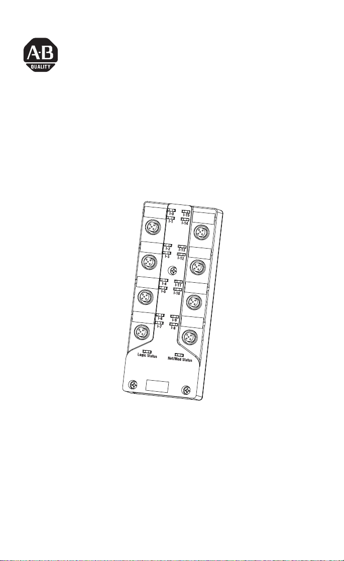
Publication 1792D-IN016B-EN-P - September 2000
Installation Instructions
ArmorBlock MaXum 16 Input Module
Series B
(Cat. No. 1792D-16BVTOD)
This ArmorBlock MaXum I/O module (Cat. No. 1792D-16BVT0D) is
a stand-alone 24V dc I/O product which communicates via a
DeviceNet network. The sealed housing of this module requires no
enclosure.
This model has 16 inputs accessed through Y splitter cables. Inputs
are 24V dc automatically configured for PNP (sourcing) or NPN
(sinking) devices. Diagnostic features included are short circuit and
open wire detection reported to the point level. Local logic control
has been added to the Series B version of this product.
30723-M

2 ArmorBlock MaXum 16 Input Module Series B
Publication 1792D-IN016B-EN-P - September 2000
Package Contents
Your package contains:
• 1 ArmorBlock MaXum Module
• Installation Instructions
(Please note: Cable bases are ordered and shipped separately.)
European Union Directive Compliance
If this product has the CE mark it is approved for installation within
the European Union and EEA regions. It has been designed and
tested to meet the following directives.
EMC Directive
This product is tested to meet Council Directive 89/336/EEC
Electromagnetic Compatibility (EMC) and the following standards, in
whole or in part, documented in a technical construction file:
• EN 50081-2 EMC - Generic Emission Standard, Part 2 -
Industrial Environment
• EN 50082-2 EMC - Generic Immunity Standard, Part 2 -
Industrial Environment
This product is intended for use in an industrial environment.
Low Voltage Directive
This product is tested to meet Council Directive 73/23/EEC Low
Voltage, by applying the safety requirements of EN 61131-2
Programmable Controllers, Part 2 - Equipment Requirements and
Tests.
For specific information required by EN 61131-2, see the appropriate
sections in this publication, as well as the following Allen-Bradley
publications:
• Industrial Automation Wiring and Grounding Guidelines For
Noise Immunity, publication 1770-4.1
• Automation Systems Catalog, publication B113
ArmorBlock MaXum 16 Input Module Series B 3
Publication 1792D-IN016B-EN-P - September 2000
Install Your ArmorBlock MaXum I/O Module
To install the module:
• Set the node address
• Mount the module to the cable base
• Connect the cord sets
• Communicate with the module
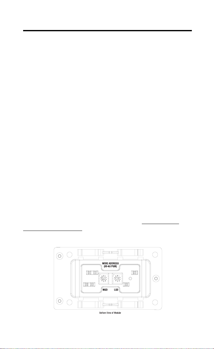
Set the Node Address
Valid node addresses are 00 to 63.
Set the node address using the rotary switches, DeviceNetManager,
RSNetWorx for DeviceNet, or other software configuration tool.
Setting the switches between 64 to 99 lets the software have address
control.
Each module is shipped set for node address 63. The switches are
located on the underside of the module. The two switches are:
• MSD (most significant digit)
• LSD (least significant digit)
To reset the node address, use a small blade screwdriver to rotate the
switches. Line up the small black dot on the switch with the number
setting you wish to use.
The rotary switches are read at module power up only. Settings
between 64 and 99 cause the module to use the last valid node
address stored internally. Example: The last setting was 40. If a
change is made to 68, and then you power up, the address will
default to 40.
30703
Example: Node address is set at 62, see small black dots.

4 ArmorBlock MaXum 16 Input Module Series B
Publication 1792D-IN016B-EN-P - September 2000
The module is equipped with AutoBaud detect. AutoBaud lets the
module read the settings already in use on your DeviceNet network
and automatically adjusts to follow those settings.
Install the Module
This module mounts to the following cable bases:
• 1792D-CBFM for KwikLink™ flat media installation
• 1792D-CB12 for 12mm drop cable installation
• 1792D-CB18 for round media trunk connection
• or other optional cable base assembly
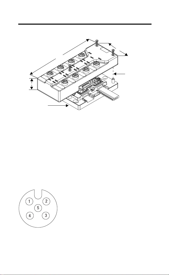
To install the module:
1. Position the module over the mounted cable base. Align the
three captive screws in the module with the accepting
receptacles in the base.
2. Tighten the screws to secure the module to the base.
IMPORTANT
The cable base should already be installed. See
publication 1792D-IN009B-EN-P for more
information on installing the cable base.
IMPORTANT
Proper alignment of the screws is necessary to
complete the connections between the module
contacts and the cable contacts.
ArmorBlock MaXum 16 Input Module Series B 5
Publication 1792D-IN016B-EN-P - September 2000
Note: Dimensions change according to the cable base and module
combination used.
Connect the Input Cord Sets to the MaXum Module
This module uses 5 pole micro (12mm) style PCB mounted
connectors.
Eight micro caps cover the connectors on your module. Remove the
caps and connect your cables to the appropriate ports. This product
has two inputs per connector. Use a “Y” splitter cable for access to all
input connections.
Use the micro caps to cover and seal unused ports. A pinout diagram
for the connectors is shown next.
Please refer to publication 889-5.0 for Rockwell Automation cables
and cord sets offerings.
Align the
screws to
properly
assemble the
module to the
base.
Cable Base 1792D-CBFM is
used for this example.
30724-M
Assembled
dimensions in (mm)
1.9 (48.26)
2
.
7
(
6
8
.
6
)
6.85 (174mm)
41452
Input Micro-Connector
(View into Socket)
Pin 1 Sensor Source Voltage
Pin 2 Input B
Pin 3 Return Logic Ground
1
Pin 4 Input A
Pin 5 Not Used
1Logic Ground is approximately 0.4V above DeviceNet V-measured at the module.
Loading...