


A " !
A
9 "A E
u

Important User Information
Because of the variety of uses for the products described in this publication, those responsible for the application and use of these products must satisfy themselves that all necessary steps have been taken to assure that each application and use meets all performance and safety requirements, including any applicable laws, regulations, codes and standards. In no event will Rockwell Automation be responsible or liable for indirect or consequential damage resulting from the use or application of these products.
Any illustrations, charts, sample programs, and layout examples shown in this publication are intended solely for purposes of example. Since there are many variables and requirements associated with any particular installation, Rockwell Automation does not assume responsibility or liability (to include intellectual property liability) for actual use based upon the examples shown in this publication.
Allen±Bradley publication SGI±1.1, Safety Guidelines for Application, Installation, and Maintenance of Solid±State Control (available from your local Rockwell Automation office), describes some important differences between solid±state equipment and electromechanical devices that should be taken into consideration when applying products such as those described in this publication.
Reproduction of the contents of this copyrighted publication, in whole or part, without written permission of Rockwell Automation, is prohibited.
Throughout this publication, notes may be used to make you aware of safety considerations. The following annotations and their accompanying statements help you to identify a potential hazard. avoid a potential hazard, and recognize the consequences of a potential hazard.
 Identifies information about practices or WARNING circumstances that can cause an explosion in a
hazardous environment, which may lead to personal
!injury or death, property damage, or economic loss.
Identifies information about practices or ATTENTION circumstances that may lead to personal injury or
death, property damage, or economic loss.
!
Identifies information that is critical for IMPORTANT successfulproduct. application and understanding of the
ATTENTION
!
Environment and Enclosure
This equipment is intended for use in a Pollution Degree 2 industrial environment, in overvoltage Category II applications (as defined in IEC publication 60664±1), at altitudes up to 2000 meters without derating.
This equipment is considered Group 1, Class A industrial equipment according to IEC/CISPR Publication 11. Without appropriate precautions, there may be potential difficulties ensuring electromagnetic compatibility in other environments due to conducted as well as radiated disturbance.
This equipment is supplied as ªopen typeº equipment. It must be mounted within an enclosure that is suitably designed for those specific environmental conditions that will be present, and appropriately designed to prevent personal injury resulting from accessibility to live parts. The interior of the enclosure must be accessible only by the use of a tool. Subsequent sections of this publication may contain additional information regarding specific enclosure type ratings that are required to comply with certain product safety certifications.
See NEMA Standards publication 250 and IEC publication 60529, as applicable, for explanations of the degrees of protection provided by different types of enclosures. Also, see the appropriate sections in this publication, as well as the Allen±Bradley publication 1770±4.1, (ªIndustrial Automation Wiring and Grounding Guidelinesº), for additional installation requirements pertaining to this equipment.
ATTENTION
!
FLEX I/O is grounded through the DIN rail to chassis ground. Use zinc plated, yellow chromated steel DIN rail to assure proper grounding. Using other DIN rail material (e.g. aluminum, plastic, etc.) which can corrode, oxidize or are poor conductors can result in improper or intermittent platform grounding.

Preventing Electrostatic Damage
ATTENTION This equipment is sensitive to electrostatic discharge, which can cause internal damage and affect normal
!operation. Follow these guidelines when you handle this equipment.
•Touch a grounded object to discharge potential static.
•Wear an approved grounding wriststrap.
•Do not touch connectors or pins on component boards.
•Do not touch components inside the equipment.
•If available, use a static±safe workstation.
•When not in use, keep modules in appropriate static±safe packing.

mm n s
mm n s
New Information
The information below summarizes the changes to the Remote I/O Adapter User Manual, publication 1794-UM009D±EN±P, since the last release.
The series E adapter is capable of recognizing the safe state data for the FLEX Integra analog modules, and allows use of 32 point FLEX I/O modules. You must use a series D or later adapter when using FLEX Integra analog modules in your system.
The following new information is included in this version of the publication:
Corrected Switch Positions
Switch positions on S! and S2 were incorrectly identified in the previous version of this publication. Corrections have been made on page 2±11 of Chapter 2.
Additional FLEX I/O Modules
New modules available since the last version of this publication have been added.
Change Bars
The areas in this manual which are different from previous editions are marked with change bars (as shown to the right of this paragraph) to indicate the addition of new or revised information.
Publication 1794 UM009D-EN-P - April 2004

soc±ii |
Summary of Changes |
Publication 1794 UM009D-EN-P - April 2004

Preface
Using This Manual
Preface Objectives
Audience
Vocabulary
Read this preface to familiarize yourself with this manual and to learn how to use it properly and efficiently.
Important:
You must use a series D or later adapter to IMPORTANT communicate with FLEX Integra analog modules. You
must use a series E or later adapter to communicate with 32 point FLEX modules.
We assume that you have previously used an Allen±Bradley programmable controller, that you are familiar with its features, and that you are familiar with the terminology we use. If not, read the user manual for your processor before reading this manual.
In this manual, we refer to:
•the individual adapter module as the ªadapter.º
•the programmable controller as the ªcontrollerº or the ªprocessor.º
•input and output modules as the ªmodule.º
What This Manual
Contains
The contents of this manual are as follows:
Table P. A
What This Manual Contains
Chapter |
Title |
What's Covered |
|
|
|
|
|
1 |
Overview of FLEX I/O and the Remote |
Describes features, capabilities, and hardware |
|
I/O Adapter Module |
components. |
||
|
|||
|
|
|
|
2 |
Installing Your Remote I/O Adapter |
Procedures and guidelines for installing the module |
|
|
|
|
|
3 |
Communicating with FLEX I/O Modules |
Hardware addressing and configuration options |
|
|
|
|
|
4 |
Troubleshooting |
Troubleshooting aids |
Appendix |
Title |
What's Covered |
|
|
|
A |
Specifications |
Module specifications |
BDifferences Between Series A, B, C, D and E Remote I/O Adapters
CSafety Approvals
Publication 17945UM009D-EN-P - April 2004
P±2 Using This Manual
Conventions |
We use these conventions in this manual: |
||||||
|
|
|
|
|
|
|
|
|
In this manual, we show: |
Like this: |
|||||
|
|
|
|
|
|
|
|
|
that there is more information about a topic |
|
|
|
|
|
|
|
|
|
|
|
|
|
|
|
in another chapter in this manual |
|
|
|
|
|
|
|
|
|
|
|
|
|
|
|
|
|
|
|
|
|
|
that there is more information about the
topic in another manual
More
For Additional Information
For additional information on FLEX I/O systems and modules, refer to the following documents:
|
|
|
|
|
|
Publications |
|
|
|
|
Catalog |
|
|
|
|
|
|
|
|
Number |
Voltage |
|
Description |
Installation |
User |
|
|
|
|
|
|
|
|||
|
|
|
|
|
|
Instructions |
Manual |
|
|
|
|
|
|
|
|
|
|
|
|
1794 |
|
1794 FLEX I/O Product Data |
179442.1 |
|
|
|
|
|
|
|
|
|
|
|
|
|
|
17944ACN |
24V dc |
ControlNet Adapter |
179445.8 |
|
|
|
|
|
|
|
|
|
|
|
|
|
|
17944ACNR |
24V dc |
Redundant Media ControlNet Adapter |
179445.18 |
|
|
|
|
|
|
|
|
|
|
|
|
|
|
17944ACN15 |
24V dc |
ControlNet Adapter |
179445.47 |
|
|
|
|
|
|
|
|
|
|
|
|
|
|
17944ACNR15 |
24V dc |
Redundant Media ControlNet Adapter |
179445.48 |
|
|
|
|
|
|
|
|
|
|
|
|
|
|
17944ADN |
24V dc |
DeviceNet Adapter |
179445.14 |
179446.5.5 |
|
|
|
|
|
|
|
|
|
|
|
|
|
17944ASB/E |
24V dc |
Remote I/O Adapter |
17944IN046 |
17944UM009 |
|
|
|
|
|
|
|
|
|
|
|
|
|
17944ASB2/D |
24V dc |
24Slot Remote I/O Adapter |
17944IN044 |
17944UM059 |
|
|
|
|
|
|
|
|
|
|
|
|
|
17944APB |
24V dc |
Profibus Adapter |
17944IN040 |
17944UM057 |
|
|
|
|
|
|
|
|
|
|
|
|
|
17944IB8 |
24V dc |
8 Sink Input Module |
179445.30 |
|
|
|
|
|
|
|
|
|
|
|
|
|
|
17944OB8 |
24V dc |
8 Source Output Module |
179445.31 |
|
|
|
|
|
|
|
|
|
|
|
|
|
|
17944IB16 |
24V dc |
16 |
Sink Input Module |
17944IN072 |
|
|
|
|
|
|
|
|
|
|
|
|
|
17944IB32 |
24V dc |
16 |
Source Output Module |
17944IN084 |
|
|
|
|
|
|
|
|
|
|
|
|
|
17944OB16 |
24V dc |
16 |
Source Output Module |
179445.3 |
|
|
|
|
|
|
|
|
|
|
|
|
|
17944OB16P |
24V dc |
16 |
Source Output Module |
179445.45 |
|
|
|
|
|
|
|
|
|
|
|
|
|
17944OB32P |
24V dc |
32 |
Electronically Fused Output Module |
17944IN090 |
|
|
|
|
|
|
|
|
|
|
|
|
|
17944IV16 |
24V dc |
16 |
Source Input Module |
179445.28 |
|
|
|
|
|
|
|
|
|
|
|
|
|
17944OV16 |
24V dc |
16 |
Sink Output Module |
179445.29 |
|
|
|
|
|
|
|
|
|
|
|
|
|
17944OB8EP |
24V dc |
8 Electronically Fused Output Module |
179445.20 |
|
|
|
|
|
|
|
|
|
|
|
|
|
|
17944OV16P |
24V dc |
16 |
Electronically Fused Output Module |
179445.52 |
|
|
|
|
|
|
|
|
|
|
|
|
|
17944IB8S |
24V dc |
Sensor Input Module |
179445.7 |
|
|
|
|
|
|
|
|
|
|
|
|
|
|
17944IB10XOB6 |
24V dc |
10 |
Input/6 Output Module |
179445.24 |
|
|
|
|
|
|
|
|
|
|
|
|
|
17944IB16XOB16P |
24V dc |
16 |
Input/16 Output Module |
17944IN083 |
|
|
|
|
|
|
|
|
|
|
|
|
|
|
|
|
Table continued on next page |
|
|
|
|
|
|
|
|
|
|
|
|
Publication 17944UM009D-EN-P - April 2004

|
|
|
|
Using This Manual |
P±3 |
|
|
|
|
|
|
|
|
|
|
|
|
|
|
|
|
|
|
|
Publications |
|
|
|
|
|
Catalog |
Voltage |
|
Description |
|
|
|
|
|
|
Number |
|
Installation |
User |
|
|
|
||
|
|
|
|
|
|
|
|||
|
|
|
|
|
Instructions |
Manual |
|
|
|
|
|
|
|
|
|
|
|
|
|
|
17948OW8 |
24V dc |
8 |
Relay Output Module |
179485.19 |
|
|
|
|
|
|
|
|
|
|
|
|
|
|
|
17948IE8 |
24V dc |
Selectable Analog 8 Input Module |
179485.6 |
|
|
|
|
|
|
|
|
|
|
|
|
|
|
|
|
17948OE4 |
24V dc |
Selectable Analog 4 Output Module |
179485.5 |
179486.5.2 |
|
|
|
|
|
|
|
|
|
|
|
|
|
|
|
17948IE4XOE2 |
24V dc |
4 |
Input/2 Output Analog Module |
179485.15 |
|
|
|
|
|
|
|
|
|
|
|
|
|
|
|
17948OF4I |
24V dc |
4 |
Output Isolated Analog Module |
179485.37 |
|
|
|
|
|
|
|
|
|
|
|
|
|
|
|
17948IF4I |
24V dc |
4 |
Input Isolated Analog Module |
179485.38 |
179486.5.8 |
|
|
|
|
|
|
|
|
|
|
|
|
|
|
17948IF2XOF2I |
24V dc |
2 |
Input/2 Output Isolated Analog Module |
179485.39 |
|
|
|
|
|
|
|
|
|
|
|
|
|
|
|
17948IR8 |
24V dc |
8 RTD Input Analog Module |
179485.22 |
179486.5.4 |
|
|
|
|
|
|
|
|
|
|
|
|
|
|
|
17948IT8 |
24V dc |
8 |
Thermocouple Input Module |
179485.21 |
179486.5.7 |
|
|
|
|
|
|
|
|
|
|
|
|
|
|
17948IRT8 |
24V dc |
8 Thermocouple/RTD Input Module |
179485.50 |
179486.5.12 |
|
|
|
|
|
|
|
|
|
|
|
|
|
|
|
17948IJ2 |
24V dc |
2 |
Frequency Input Module |
179485.49 |
179486.5.11 |
|
|
|
|
|
|
|
|
|
|
|
|
|
|
17948ID2 |
24V dc |
2 |
Channel Frequency Input Module |
179485.63 |
179486.5.15 |
|
|
|
|
|
|
|
|
|
|
|
|
|
|
17948IP4 |
24V dc |
2 |
Channel Pulse Counter Module |
179485.64 |
179486.5.16 |
|
|
|
|
|
|
|
|
|
|
|
|
|
|
17948HSC |
24V dc |
High Speed Counter Module |
179485.67 |
179486.5.10 |
|
|
|
|
|
|
|
|
|
|
|
|
|
|
|
17948IC16 |
48V dc |
48V dc 16 Input Module |
179485.53 |
|
|
|
|
|
|
|
|
|
|
|
|
|
|
|
|
17948OC16 |
48V dc |
48V dc Output Module |
179485.54 |
|
|
|
|
|
|
|
|
|
|
|
|
|
|
|
|
17948IA8 |
120V ac |
8 |
Input Module |
179485.9 |
|
|
|
|
|
|
|
|
|
|
|
|
|
|
|
17948OA8 |
120V ac |
8 |
Output Module |
179485.10 |
|
|
|
|
|
|
|
|
|
|
|
|
|
|
|
17948IA8I |
120V ac |
Isolated 8 Input Module |
179485.55 |
|
|
|
|
|
|
|
|
|
|
|
|
|
|
|
|
17948OA8I |
120V ac |
Isolated Output Module |
179485.56 |
|
|
|
|
|
|
|
|
|
|
|
|
|
|
|
|
17948IA16 |
120V ac |
16 Input Module |
179485.60 |
|
|
|
|
|
|
|
|
|
|
|
|
|
|
|
|
17948OA16 |
120V ac |
16 Output Module |
179485.61 |
|
|
|
|
|
|
|
|
|
|
|
|
|
|
|
|
17948IM8 |
220V |
8 |
Input Module |
179485.57 |
|
|
|
|
|
|
ac/dc |
|
|
|
|
|
|
|
|
|
|
|
|
|
|
|
|
|
|
|
|
|
|
|
|
|
|
|
|
17948OM8 |
220V |
8 |
Output Module |
179485.58 |
|
|
|
|
|
|
ac/dc |
|
|
|
|
|
|
|
|
|
|
|
|
|
|
|
|
|
|
|
|
|
|
|
|
|
|
|
|
17948TB2 |
|
28wire Terminal Base |
17948IN070 |
|
|
|
|
|
|
17948TB3 |
|
38wire Terminal Base |
|
|
|
|
||
|
|
|
|
|
|
|
|||
|
|
|
|
|
|
|
|
|
|
|
17948TBN |
|
Terminal Base Unit |
17948IN016 |
|
|
|
|
|
|
|
|
|
|
|
|
|
|
|
|
17948TBNF |
|
Fused Terminal Base Unit |
179485.17 |
|
|
|
|
|
|
|
|
|
|
|
|
|
|
|
|
17948TB3T |
|
Temperature Terminal Base Unit |
179485.41 |
|
|
|
|
|
|
|
|
|
|
|
|
|
|
|
|
17948TB3S |
|
Spring Clamp Terminal Base Unit |
179485.42 |
|
|
|
|
|
|
|
|
|
|
|
|
|
|
|
|
17948TB3TS |
|
Spring Clamp Temperature Base Unit |
179485.43 |
|
|
|
|
|
|
|
|
|
|
|
|
|
|
|
|
17948TB3G |
|
Terminal Base Unit |
179485.51 |
|
|
|
|
|
|
|
|
|
|
|
|
|
|
|
|
17948TB3GS |
|
Spring Clamp Terminal Base Unit |
179485.59 |
|
|
|
|
|
|
|
|
|
|
|
|
|
|
|
|
17948TB32 |
|
Cage Clamp Terminal Base Unit |
17948IN085 |
|
|
|
|
|
|
|
|
|
|
|
|
|
|
|
|
17948TB32S |
|
Spring Clamp Terminal Base Unit |
17948IN085 |
|
|
|
|
|
|
|
|
|
|
|
|
|
|
|
|
|
|
|
Table continued on next page |
|
|
|
|
|
|
|
|
|
|
|
|
|
|
|
Publication 17948UM009D-EN-P - April 2004

|
|
P±4 |
Using This Manual |
|
|
|
|
|
||
|
|
|
|
|
|
|
|
|
|
|
|
|
|
|
|
|
|
|
Publications |
|
|
|
|
|
|
|
Catalog |
Voltage |
Description |
|
|
|
|
|
|
|
|
Number |
Installation |
User |
|
||
|
|
|
|
|
|
|
|
|||
|
|
|
|
|
|
|
|
Instructions |
Manual |
|
|
|
|
|
|
|
|
|
|
|
|
|
|
|
|
|
1794;CE1, ;CE3 |
|
Extender Cables |
1794;5.12 |
|
|
|
|
|
|
|
|
|
|
|
|
|
|
|
|
|
|
1794;NM1 |
|
Mounting Kit |
1794;5.13 |
|
|
|
|
|
|
|
|
|
|
|
|
|
|
|
|
|
|
1794;PS13 |
24V dc |
Power Supply |
1794;5.35 |
|
|
|
|
|
|
|
|
|
|
|
|
|
|
|
|
|
|
1794;PS3 |
24V dc |
Power Supply |
1794;5.71 |
|
|
|
|
|
|
|
|
|
|
|
|
|
|
|
|
|
|
|
|
FLEX Ex |
|
|
|
|
|
|
|
|
|
|
|
|
|
|
|
|
|
|
|
1797;IBN16 |
See note |
16 NAMUR Digital Input Module |
1794;IN072 |
|
|
|
|
|
|
|
|
|
|
|
|
|
|
|
|
|
|
1797;OB4D |
See note |
4 NI, Ex Source Digital Output Module |
1794;5.6 |
|
|
|
|
|
|
|
|
|
|
|
|
|
|
|
|
|
|
1797;IE8 |
See note |
8 Selectable Input Module |
1794;5.5 |
|
|
|
|
|
|
|
|
|
|
|
|
|
|
|
|
|
|
1797;IE8NF |
See note |
8 Selectable Filter Analog Input Module |
1794;5.31 |
|
|
|
|
|
|
|
|
|
|
|
|
|
|
|
|
|
|
1797;OE4 |
See note |
Selectable Analog 4 Output Module |
1794;5.3 |
|
|
|
|
|
|
|
|
|
|
|
|
|
|
|
|
|
|
1797;IRT8 |
See note |
8 Thermocouple/RTD Input Module |
1794;5.4 |
|
|
|
|
|
|
|
|
|
|
|
|
|
|
|
|
|
|
1797;IJ2 |
See note |
2 Frequency Input Module |
1794;5.9 |
|
|
|
|
|
|
|
|
|
|
|
|
|
|
|
|
|
|
1797;TB3 |
|
3;wire Screw Clamp Terminal Base |
1797;5.1 |
|
|
|
|
|
|
|
1797;TB3S |
|
3;wire Spring Clamp Terminal Base |
1797;5.2 |
|
|
|
|
|
|
|
|
|
|
|
|
|
|
|
|
|
|
1797;BIC |
See note |
I.S. Bus Isolator |
1797;5.13 |
|
|
|
|
|
|
|
|
|
|
|
|
|
|
|
|
|
|
1797;CEC |
See note |
FLEX Ex Bus Connector |
1797;5.13 |
|
|
|
|
|
|
|
|
|
|
|
|
|
Note: Intrinsically Safe Voltage
ATTENTION
!
FLEX I/O is grounded through the DIN rail to chassis ground. Use zinc plated, yellow chromated steel DIN rail to assure proper grounding. Using other DIN rail materials (e.g. aluminum, plastic, etc.) which can corrode, oxidize or are poor conductors can result in improper or intermittent platform grounding.
Publication 1794;UM009D-EN-P - April 2004
Using This Manual |
P±5 |
ATTENTION Preventing Electrostatic Discharge
This equipment is sensitive to electrostatic
!discharge, which can cause internal damage and affect normal operation. Follow these guidelines when you handle this equipment:
•Touch a grounded object to discharge potential static.
•Wear an approved grounding wriststrap.
•Do not touch connectors or pins on component boards.
•Do not touch circuit components inside the equipment.
•If available, use a static±safe workstation.
•When not in use, keep modules in appropriate static±safe packaging.
WARNING Remove field-side power before removing or inserting this module. This module is designed so
!you can remove and insert it under backplane power. When you remove or insert a module with field-side power applied, an electrical arc may occur. An electrical arc can cause personal injury or property damage by:
•sending an erroneous signal to your system's field devices causing unintended machine motion
•causing an explosion in a hazardous environment Repeated electrical arcing causes excessive wear to contacts on both the module and its mating connector. Worn contacts may create electrical resistance.
Publication 1794 UM009D-EN-P - April 2004

P±6 |
Using This Manual |
Summary
This preface gave you information on how to use this manual efficiently. The next chapter introduces you to the remote I/O adapter module.
Publication 1794 UM009D-EN-P - April 2004

Table of Contents
Overview of FLEX I/O and your Remote I/O Adapter Module
Installing Your Remote I/O
Adapter Module
Communicating with FLEX I/O Modules
Chapter 1
Chapter Objectives . . . . . . . . . . . . . . . . . . . . . . . . . . . . . . . . . . . |
1-1 |
The FLEX I/O System . . . . . . . . . . . . . . . . . . . . . . . . . . . . . . . . . |
1-1 |
How FLEX I/O Modules Communicate with Programmable Controllers |
1-2 |
Hardware Components . . . . . . . . . . . . . . . . . . . . . . . . . . . . . . . . |
1-3 |
Diagnostic Indicators . . . . . . . . . . . . . . . . . . . . . . . . . . . . . . . . |
1-3 |
Reset Pushbutton . . . . . . . . . . . . . . . . . . . . . . . . . . . . . . . . . . |
1-4 |
Remote I/O Wiring . . . . . . . . . . . . . . . . . . . . . . . . . . . . . . . . . . |
1-4 |
Power Wiring . . . . . . . . . . . . . . . . . . . . . . . . . . . . . . . . . . . . . . |
1-4 |
Address Switch Assemblies . . . . . . . . . . . . . . . . . . . . . . . . . . . |
1-4 |
Chapter Summary . . . . . . . . . . . . . . . . . . . . . . . . . . . . . . . . . . . . |
1-4 |
Chapter 2
Chapter Objectives . . . . . . . . . . . . . . . . . . . . . . . . . . . . . . . . . . . |
2-1 |
Power Requirements . . . . . . . . . . . . . . . . . . . . . . . . . . . . . . . . . . |
2-3 |
Mounting the Remote I/O Adapter . . . . . . . . . . . . . . . . . . . . . . . . . |
2-3 |
Mounting on a DIN Rail before installing the terminal base units . . |
2-3 |
Mounting (or Replacing) the Adapter on an Existing System . . . . |
2-4 |
Mounting on a Wall or Panel . . . . . . . . . . . . . . . . . . . . . . . . . . . |
2-5 |
Wiring . . . . . . . . . . . . . . . . . . . . . . . . . . . . . . . . . . . . . . . . . . . . . |
2-7 |
Setting the Switches . . . . . . . . . . . . . . . . . . . . . . . . . . . . . . . . . . |
2-8 |
Starting I/O Group . . . . . . . . . . . . . . . . . . . . . . . . . . . . . . . . . . |
2-8 |
I/O Rack Number . . . . . . . . . . . . . . . . . . . . . . . . . . . . . . . . . . . |
2-8 |
Hold Inputs . . . . . . . . . . . . . . . . . . . . . . . . . . . . . . . . . . . . . . . |
2-8 |
Rack Fault Select Switch (RFS) . . . . . . . . . . . . . . . . . . . . . . . . |
2-9 |
Addressing Mode Selection Switches . . . . . . . . . . . . . . . . . . . . |
2-9 |
Communication Rate . . . . . . . . . . . . . . . . . . . . . . . . . . . . . . . . |
2-10 |
Processor Restart Lockout (PRL) . . . . . . . . . . . . . . . . . . . . . . . |
2-10 |
Hold Last State (HLS) . . . . . . . . . . . . . . . . . . . . . . . . . . . . . . . |
2-10 |
Setting the Mode Selection Switches . . . . . . . . . . . . . . . . . . . . . . . |
2-12 |
Setting the Address Switches . . . . . . . . . . . . . . . . . . . . . . . . . . . . |
2-13 |
Setting the Address Switches for Complementary I/O . . . . . . . . . . . |
2-15 |
Primary Rack . . . . . . . . . . . . . . . . . . . . . . . . . . . . . . . . . . . . . |
2-15 |
Complementary Rack . . . . . . . . . . . . . . . . . . . . . . . . . . . . . . . . |
2-15 |
Chapter Summary . . . . . . . . . . . . . . . . . . . . . . . . . . . . . . . . . . . . |
2-15 |
Chapter 3
Chapter Objectives . . . . . . . . . . . . . . . . . . . . . . . . . . . . . . . . . . . |
3-1 |
FLEX I/O Module Data . . . . . . . . . . . . . . . . . . . . . . . . . . . . . . . . . |
3-1 |
Addressing I/O . . . . . . . . . . . . . . . . . . . . . . . . . . . . . . . . . . . . . . |
3-2 |
Analog (Block Transfer) Modules . . . . . . . . . . . . . . . . . . . . . . . . . |
3-5 |
Publication 1794=UM009D-EN-P - April 2004

ii |
Table of Contents |
Troubleshooting
Specifications
Differences Between
Remote I/O Adapter Series
A, B, C, D and E
Safety Approvals
Standard Addressing . . . . . . . . . . . . . . . . . . . . . . . . . . . . . . . . . . |
3-6 |
Standard - 32 Addressing . . . . . . . . . . . . . . . . . . . . . . . . . . . . . . |
3-7 |
Compact Addressing . . . . . . . . . . . . . . . . . . . . . . . . . . . . . . . . . . |
3-8 |
Compact Mode . . . . . . . . . . . . . . . . . . . . . . . . . . . . . . . . . . . . |
3-8 |
Complementary Addressing Mode . . . . . . . . . . . . . . . . . . . . . . . . |
3-12 |
Complementary Mode - 168point . . . . . . . . . . . . . . . . . . . . . . . |
3-12 |
Complementary Mode - 88point . . . . . . . . . . . . . . . . . . . . . . . . |
3-13 |
Complementary - 32 Addressing . . . . . . . . . . . . . . . . . . . . . . . . . |
3-15 |
Mapping Data into the Image Tables . . . . . . . . . . . . . . . . . . . . . . . |
3-16 |
Determining Rack Size . . . . . . . . . . . . . . . . . . . . . . . . . . . . . . . . . |
3-16 |
Operating Modes . . . . . . . . . . . . . . . . . . . . . . . . . . . . . . . . . . . . . |
3-18 |
Chapter Summary . . . . . . . . . . . . . . . . . . . . . . . . . . . . . . . . . . . . |
3-18 |
Chapter 4
Chapter Objectives . . . . . . . . . . . . . . . . . . . . . . . . . . . . . . . . . . . |
4-1 |
Fault Conditions . . . . . . . . . . . . . . . . . . . . . . . . . . . . . . . . . . . . . |
4-1 |
Troubleshooting with the Indicator Lights . . . . . . . . . . . . . . . . . . . . |
4-1 |
Chapter Summary . . . . . . . . . . . . . . . . . . . . . . . . . . . . . . . . . . . . |
4-3 |
Appendix A
Specifications . . . . . . . . . . . . . . . . . . . . . . . . . . . . . . . . . . . . . . . |
A-1 |
Appendix B
Differences Between Remote I/O Adapter Series A, B, C, D and E . . |
B-1 |
Appendix C
Safety Approvals . . . . . . . . . . . . . . . . . . . . . . . . . . . . . . . . . . . . . |
C-1 |
Publication 17948UM009D-EN-P - April 2004
Ch pt r 1
Chapter Objectives
The FLEX I/O System
Adapter
Overview of FLEX I/O and your Remote I/O Adapter Module
In this chapter, we tell you about:
•what the FLEX I/O system is and what it contains
•how FLEX I/O modules communicate with programmable controllers
•the features of your adapter module
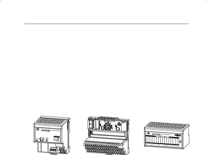
FLEX I/O is a small, modular I/O system for distributed applications that performs all of the functions of rack-based I/O. The FLEX I/O system contains the following components shown below:
Terminal Base
I/O Module
20125
•adapter/power supply ± powers the internal logic for as many as eight I/O modules
•terminal base ± contains a terminal strip to terminate wiring for twoor three-wire devices
•I/O module ± contains the bus interface and circuitry needed to perform specific functions related to your application
Publication 1794 UM009D-EN-P - April 2004

1±2 |
Overview of FLEX I/O and your Remote I/O Adapter Module |
How FLEX I/O Modules Communicate with Programmable Controllers
Data transfer to and from the remote I/O adapter/power supply and discrete I/O modules occurs every flexbus scan. This provides the controller with updated data.
The remote I/O adapter/power supply transfers data to the analog I/O module (block transfer write) and from the analog I/O module (block transfer read) using BTW and BTR instructions in your ladder diagram program. These instructions let the adapter obtain input values and status from the I/O module, and let you send output values to establish the module's mode of operation. The communication process is described in the following illustration.
Allen Bradley
|
|
ADAPTER |
|
|
24VDC |
|||
|
|
LOCAL |
POWER SUPPLY |
|||||
PWR |
ACTIVE |
|
FAULT |
FAULT |
|
|||
|
|
|
|
|
|
|
|
RIO ADAPTER |
1794=ASB
1
The adapter transfers your configuration data to the module using a BTW.
Flexbus
2
External devices transmit analog signals to the module.
Allen Bradley |
1794-IE8 |
ANALOG INPUT
2
4 |
|
|
|
|
|
|
|
|
INPUT 0 INPUT 1 |
INPUT 2 INPUT 3 |
INPUT 4 |
INPUT 5 |
INPUT 6 |
INPUT 7 |
|
Your ladder program instructs the |
I V |
I V |
I V I V |
I V |
I V |
I V |
I V |
|
|
|
|
|
|
|
|
adapter to perform a BTR of the values |
|
|
|
|
|
|
|
and stores them in a data table. |
|
|
|
|
|
|
|
5 |
|
|
|
|
|
|
3 |
The adapter and module determine that the transfer was made without error and input values are within specified range.
6
Your ladder program can use and/or move the data (if valid) before it is written over by the transfer of new data in a subsequent transfer.
7
Your ladder program performs BTWs to the module when you power it up, and any time you wish to reconfigure the module.
The module converts analog signals into binary format and stores these values until the adapter requests their transfer.
Publication 1794=UM009D-EN-P - April 2004
Overview of FLEX I/O and your Remote I/O Adapter Module |
1±3 |
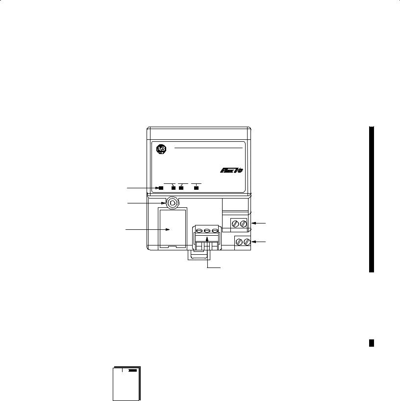
Hardware Components
The adapter module consists of the following major components:
•diagnostic indicators
•reset pushbutton
•remote I/O wiring connections
•24V dc power wiring connections
•address/group switch assemblies
|
|
Allen6Bradley |
|
|
|
|
24 VDC |
|
ADAPTER |
LOCAL |
POWER SUPPLY |
|
|
|
|
PWR |
ACTIVE FAULT |
FAULT |
RIO ADAPTER |
|
|
||
Diagnostic Indicators |
|
|
1794-ASB |
|
|
|
|
Reset Pushbutton |
|
|
|
|
|
|
24V dc Common Wiring Connections |
Address/Group Switches |
|
|
|
|
|
|
+24V dc Wiring Connections |
|
|
|
Remote I/O Wiring Connections (connector part no. 942029-03) |
Diagnostic Indicators
Diagnostic indicators are located on the front panel of the adapter module. They show both normal operation and error conditions in your remote I/O system. The indicators are:
•Power ON (green)
•Adapter ACTIVE (green)
•Adapter FAULT (red)
• LOCAL FAULT (red)
A complete description of the diagnostic indicators and how to use them for troubleshooting is explained in chapter 4.
Publication 17946UM009D-EN-P - April 2004
1±4 |
Overview of FLEX I/O and your Remote I/O Adapter Module |
Flip open |
|
|
cover |
8 |
8 |
|
7 |
7 |
6 |
6 |
5 |
5 |
4 |
4 |
3 |
3 |
2 |
2 |
1 |
1 |
ON |
ON |
S1 S2
Chapter Summary
Reset Pushbutton
Use the reset pushbutton to reset the adapter module and resume communication when a communication error occurs. (The adapter's processor restart lockout switch (PRL) must be in the ªlocked outº position.) If the adapter is not locked out by the PRL switch, it
will be automatically reset via special commands sent over the communication link.
Important: Do not cycle power to the adapter to clear a fault. All queued block transfer instructions will be lost.
Remote I/O Wiring
The remote I/O wiring termination is made to a plug-in connector on the front of the adapter module. Refer to Chapter 2 for information on wiring the connector.
Power Wiring
Connections are provided for connecting the required 24V dc power to the front of the module. The power wiring can be daisy-chained to the terminal base unit located next to the adapter to supply power to the module installed in that base unit. Wiring information is shown in Chapter 2.
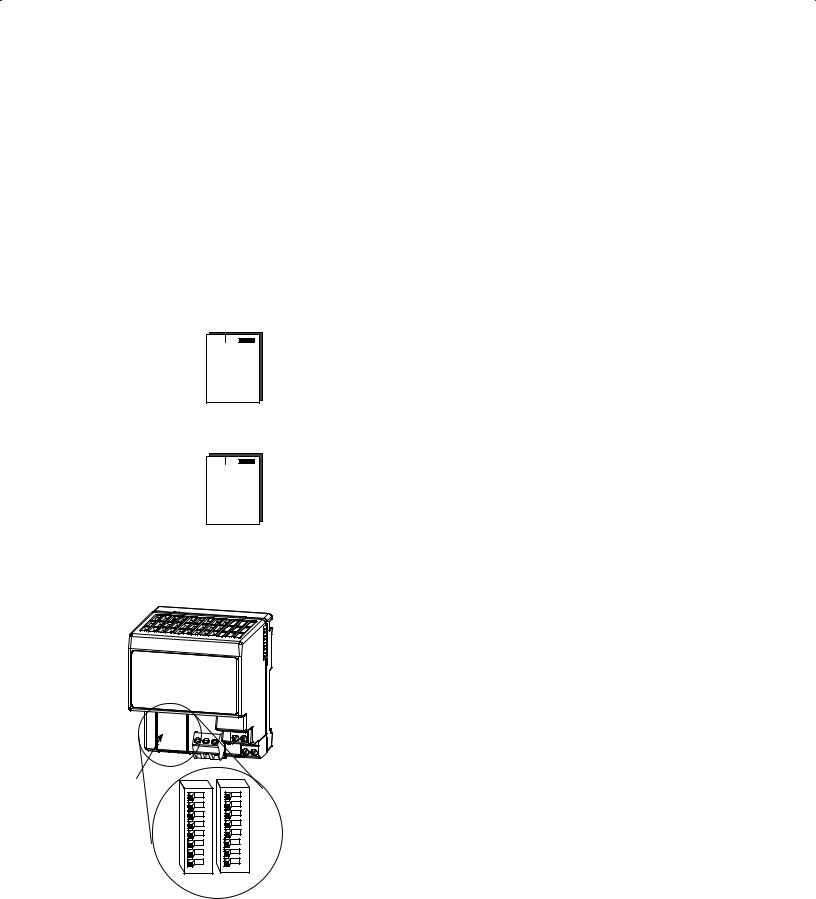
Address Switch Assemblies
Multi-position switches are provided for:
•starting I/O group
•I/O rack number
•hold inputs
•mode switches for mode 0, mode 1, mode 2, mode 3 and mode 4
•rack fault
•communication rate
•processor restart lockout (PRL)
•hold last state (outputs)
These switches are accessed by lifting the hinged cover on the front of the module. Refer to Chapter 2 for switch settings.
In this chapter you learned about the FLEX I/O system and features of the remote I/O adapter module.
Publication 1794 UM009D-EN-P - April 2004

Ch pt r 2
Installing Your Remote I/O
Adapter Module
Chapter Objectives
This chapter describes the procedures for installing your remote I/O adapter module. These include:
•power requirements
•mounting the remote I/O adapter
•setting the module switches
ATTENTION
!
Environment and Enclosure
This equipment is intended for use in a Pollution Degree 2 industrial environment, in overvoltage Category II applications (as defined in IEC publication 60664±1), at altitudes up to 2000 meters without derating.
This equipment is considered Group 1, Class A industrial equipment according to IEC/CISPR Publication 11. Without appropriate precautions, there may be potential difficulties ensuring electromagnetic compatibility in other environments due to conducted as well as radiated disturbance.
This equipment is supplied as ªopen typeº equipment. It must be mounted within an enclosure that is suitably designed for those specific environmental conditions that will be present, and appropriately designed to prevent personal injury resulting from accessibility to live parts. The interior of the enclosure must be accessible only by the use of a tool. Subsequent sections of this publication may contain additional information regarding specific enclosure type ratings that are required to comply with certain product safety certifications.
See NEMA Standards publication 250 and IEC publication 60529, as applicable, for explanations of the degrees of protection provided by different types of enclosures. Also, see the appropriate sections in this publication, as well as the Allen±Bradley publication 1770±4.1, (ªIndustrial Automation Wiring and Grounding Guidelinesº), for additional installation requirements pertaining to this equipment.
Publication 1794 UM009D-EN-P - April 2004

2±2 |
Installing Your Remote I/O Adapter Module |
ATTENTION
!
Preventing Electrostatic Discharge
This equipment is sensitive to electrostatic discharge, which can cause internal damage and affect normal operation. Follow these guidelines when you handle this equipment:
•Touch a grounded object to discharge potential static.
•Wear an approved grounding wriststrap.
•Do not touch connectors or pins on component boards.
•Do not touch circuit components inside the equipment.
•If available, use a static±safe workstation.
•When not in use, keep modules in appropriate static±safe packaging.
ATTENTION
!
Remove field-side power before removing or inserting this module. This module is designed so you can remove and insert it under backplane power. When you remove or insert a module with field-side power applied, an electrical arc may occur. An electrical arc can cause personal injury or property damage by:
•sending an erroneous signal to your system's field devices causing unintended machine motion
•causing an explosion in a hazardous environment
Repeated electrical arcing causes excessive wear to contacts on both the module and its mating connector. Worn contacts may create electrical resistance.
ATTENTION
!
FLEX I/O is grounded through the DIN rail to chassis ground. Use zinc plated, yellow chromated steel DIN rail to assure proper grounding. Using other DIN rail materials (e.g. aluminum, plastic, etc.) which can corrode, oxidize or are poor conductors can result in improper or intermittent platform grounding.
Publication 1794 UM009D-EN-P - April 2004
Installing Your Remote I/O Adapter Module |
2±3 |
Power Requirements
Mounting the Remote I/O
Adapter
A
The Remote I/O adapter module requires a current of 450mA at 24V dc from an external power supply for flexbus operation. This is sufficient to support the flexbus current requirements of 8 modules. Remember to add this amount to current requirements for other modules using the same 24V supply.
The remote I/O adapter module can be DIN rail or wall/panel mounted. Refer to the specific method of mounting below.
Mounting on a DIN Rail before installing the terminal base units
B
C
C
1.Position the remote I/O adapter module A on a 35 x 7.5mm DIN rail B (A-B pt. no. 199-DR1; 46277-3; EN 50022) at a slight angle.
2.Rotate the adapter module onto the DIN rail with the top of the rail hooked under the lip on the rear of the adapter module.
3.Press the adapter module down onto the DIN rail until flush. Locking tab (C) will snap into position and lock the adapter module to the DIN rail.
If the adapter module does not lock in place, use a screwdriver or similar device to move the locking tab down while pressing the adapter module flush onto the DIN rail and release the locking tab to lock the adapter module in place. If necessary, push up on the locking tab to lock.
4.Connect the adapter wiring as shown under ªWiringº later in this document.
Make certain that the DIN rail is properly IMPORTANT grounded to the panel. Refer to ªIndustrial
Automation Wiring and Grounding Guidelines,º publication 1770-4.1.
Publication 1794 UM009D-EN-P - April 2004
2±4 |
Installing Your Remote I/O Adapter Module |
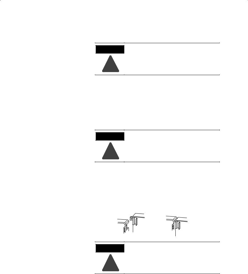
Mounting (or Replacing) the Adapter on an Existing System
ATTENTION
!
If you connect or disconnect wiring while the field side power is on, an electrical arc can occur. This could cause an explosion in hazardous location installations. Be sure that power is removed or the area is nonhazardous before proceeding.
1.Remove the RIO plug-in connector from the front of the adapter.
2.Disconnect any wiring connected to the adjacent terminal base.
3.Using a screwdriver or similar tool, open the lock and remove the module from the base unit to which the adapter will be attached.
4.Push the flexbus connector toward the right side of the terminal base to unplug the backplane connection.
ATTENTION
!
Make certain that the flexbus connector is completely clear of the adapter. The slide must be completely to the right and the raised spot on the slide visible.
5.Release the locking tab and remove the adapter.
6.Before installing the new adapter, notice the notch on the right rear of the adapter. This notch accepts the hook on the terminal base unit. The notch is open at the bottom. The hook and adjacent connection point keep the terminal base and adapter tight together, reducing the possibility of a break in communication over the backplane.
ATTENTION
!
Make certain that the hook on the terminal base is properly hooked into the adapter. Failure to lock the hook into the adjacent base/adapter can result in loss of communication on the backplane.
7.Place the adapter next to the terminal base unit and push down to mate the hook into slot.
Publication 1794 UM009D-EN-P - April 2004
 Loading...