


 Loading...
Allen-Bradley |
|
|
PLC-5 Backup |
User |
|
|
||
Communication |
Manual |
|
Module |
||
|
||
(1785-BCM, 1785-BEM) |
|
|
product icon |
|

Important User Information |
Because of the variety of uses for this product and because of the differences |
||
|
between solid state products and electromechanical products, those responsible |
||
|
for applying and using this product must satisfy themselves as to the |
||
|
acceptability of each application and use of this product. For more information, |
||
|
refer to publication SGI-1.1 (Safety Guidelines For The Application, |
||
|
Installation and Maintenance of Solid State Control). |
||
|
The illustrations, charts, and layout examples shown in this manual are intended |
||
|
solely to illustrate the text of this manual. Because of the many variables and |
||
|
requirements associated with any particular installation, Allen-Bradley |
||
|
Company cannot assume responsibility or liability for actual use based upon the |
||
|
illustrative uses and applications. |
||
|
No patent liability is assumed by Allen-Bradley Company with respect to use of |
||
|
information, circuits, equipment or software described in this text. |
||
|
Reproduction of the contents of this manual, in whole or in part, without written |
||
|
permission of the Allen-Bradley Company is prohibited. |
||
|
Throughout this manual we make notes to alert you to possible injury to people |
||
|
or damage to equipment under specific circumstances. |
||
|
|
|
|
|
|
ATTENTION: Identifies information about practices or |
|
|
|
circumstances that can lead to personal injury or death, property |
|
|
|
damage or economic loss. |
|
|
|
|
|
Attention helps you:
-Identify a hazard
-Avoid the hazard
-recognize the consequences
Important: Identifies information that is critical for successful application and understanding of the product.

Summary of Changes
Summary of Changes
|
Summary of Changes |
This release of the publication contains new updated information. |
|
|
To help you find updated information in this release of the manual, we |
|
|
|
|
|
have included change bars as shown to the left of this paragraph. |

Preface
Using This Manual
Manual Objectives |
This manual shows you how to use 1785-BCM series B backup communication |
|
modules with a PLC-5 programmable controller (PLC-5/15 series B, -5/20, |
|
-5/25, -5/30, -5/40, and -5/60 processors). These modules enable high-speed |
|
communication transfer between two PLC-5 processors and provide system |
|
backup should the processor or other equipment in the system fail. |
|
In this manual we describe: |
|
backup system concepts |
|
procedures for installing and operating your modules |
|
various programming techniques |
Audience |
Before you read this manual or attempt to use 1785-BCM modules, you should |
|
be familiar with PLC-5 programmable controllers. In addition, you need to be |
|
familiar with: |
|
6200 Series Software |
|
remote I/O system |
|
Data Highway Plus network |
|
block-transfer instructions |
What this Manual Contains The following table lists each chapter of this manual and describes the contents of each.
If you want to read about: |
|
Refer to chapter: |
|
|
|
|
|
|
an overview of backup concepts; description of backup |
1 |
± Backup Concepts for the PLC-5 System |
system that uses 1785-BCM module. |
|
|
|
|
|
a description of 1785-BCM module hardware. |
2 |
± Understanding the 1785-BCM Module Hardware Components |
|
|
|
procedures for installing the1785-BCM module; procedures |
3 |
± Installing Your 1785-BCM Series B Backup System |
for connecting the backup system. |
|
|
|
|
|
description of 1785-BEM backup expansion module and |
4 |
± Installing Your 1785-BEM Module |
procedures for installing |
|
|
|
|
|
an overview of how the 1785-BCM module and the backup |
5 |
± Operating Your PLC-5 Backup System |
system operate; procedures for starting, powering-up, |
|
|
disconnecting, and restarting a repaired system. |
|
|
|
|
|
considerations for timing, divergence, I/O forces, Data |
6 |
± Switchover Considerations |
Highway Plus switching, Remote I/O switching, special |
|
|
sections of the data table, and data integrity. |
|
|
|
|
|
i

Preface
If you want to read about: |
Refer to chapter: |
|
|
|
|
two methods you can use to program your backup system; |
7 ± Programming Techniques |
considerations for using instructions that can cause |
|
problems in your backup system. |
|
|
|
1785-BCM module faults (as indicated by the module's |
8 ± Diagnosing Faults |
status indicators and bits of the system status word) and |
|
procedures for correcting faults. |
|
|
|
specifications for the 1785-BCM module. |
9 ± Specifications |
|
|
sample Programs for method 1 (transferring one block of |
Appendix A ± Sample Programs |
data at a time) and method 2 ( transferring multiple blocks |
|
of data at a time); data table transfer times for both |
|
programming methods. |
|
|
|
answers to common PLC-5 backup system questions; |
Appendix B ± Reference Information |
delay times between the primary and the secondary |
|
processor for both programming methods and formulas for |
|
determining delay times. |
|
|
|
describes differences between a 1785-BCM series A |
Appendix C ± Using a Series A 1785-BCM Module |
backup module and a 1785-BCM series B backup module |
|
|
|
|
PLC-5 Processor Reference |
In this manual, the term PLC-5 processor refers to the following processors: |
|
|
PLC-5/11 |
|
|
|
|
|
PLC-5/15 |
|
|
|
|
|
PLC-5/20 |
|
|
PLC-5/25 |
|
|
PLC-5/30 |
|
|
PLC-5/40 |
|
|
PLC-5/60 |
|
|
PLC-5/80 |
|
|
|
|
|
Contact your Allen-Bradley Sales Office or your Allen-Bradley distributor for |
|
|
additional PLC-5 processors that can be configured with the 1785-BCM |
|
|
modules. |
|
Terms and Conventions |
Some terms used in this manual may be unfamiliar to you. We list these terms |
|
|
with a brief definition of each. |
|
|
HSSL is the 1785-BCM module's High-Speed Serial Link. It is a dedicated |
|
|
communication link between the primary and secondary 1785-BCM modules |
|
|
and is used to pass I/O, status, and data table information. |
|
|
Primary System is the PLC-5 processor that controls the I/O and the other |
|
|
equipment associated with that processor. |
|
|
Secondary System is the PLC-5 processor that is ready to assume control of |
|
|
the I/O and the equipment associated with that processor. |
|
|
Backup System is the primary and secondary systems. |
ii

Preface
Switchover is the transfer of I/O control from the primary processor to the secondary processor.
Bumpless switchover is the transfer of I/O control from the primary processor to the secondary processor where the operation of the process being controlled is not affected.
Asynchronous processing is processing where the ladder program scan and the block-transfer scan operate independently of each other within the same scan time.
BTW is block-transfer write; transfer of up to 64 words from the processor to the block-transfer module.
BTR is block transfer read; transfer of up to 64 words from the block transfer module to the processor.
Smart Switch Interface is a remote I/O interface in the 1785-BCM module that responds to secondary scanner poll commands with actual input values from the remote I/O link, making the scanner think it is talking with
remote I/O.
Related Publications |
For more information about components used with the 1785-BCM module in a |
|
||
|
PLC-5 backup system, refer to the following publications: |
|
||
|
|
|
|
|
|
Publication Title |
Publication Number |
|
|
|
|
|
|
|
|
|
|
|
|
|
Enhanced and Ethernet PLC-5 Programmable Controllers |
1785-6.5.12 |
|
|
|
User Manual |
|
|
|
|
|
|
|
|
|
Classic 1785 PLC-5 Family Programmable Controllers Hardware |
1785-6.6.1 |
|
|
|
Installation Manual |
|
|
|
|
|
|
|
|
|
PLC-5 Programming Software Documentation Set |
6200-N8.001 |
|
|
|
PLC-5 Programming Software: Installing and |
|
|
|
|
6200-6.4.6 |
|
|
|
|
Configuring the Software |
|
|
|
|
PLC-5 Programming Software: Programming |
|
|
|
|
6200-6.4.7 |
|
|
|
|
PLC-5 Programming Software: Instruction Set Reference |
|
|
|
|
6200-6.4.11 |
|
|
|
|
PLC-5 Programming Software: I/O Configuration Software |
6200-6.4.12 |
|
|
|
|
|
|
|
|
Remote I/O Adapter Module (cat. no. 1771-ASB) Installation Data |
1771-2.162 |
|
|
|
|
|
|
|
iii

Backup Concepts for the PLC-5 System
Understanding the
1785-BCM Hardware
Components
Table of Contents
Chapter 1
Chapter Objectives . . . . . . . . . . . . . . . . . . . . . . . . . . . . . . . . . . . 1-1 Why Use a Backup System? . . . . . . . . . . . . . . . . . . . . . . . . . . . . 1-1 Applying 1785-BCM Backup Communication Modules to
the PLC-5 Programmable Controller . . . . . . . . . . . . . . . . . . . . . . 1-2 What to do Next . . . . . . . . . . . . . . . . . . . . . . . . . . . . . . . . . . . . . . 1-7
Chapter 2
Chapter Objectives . . . . . . . . . . . . . . . . . . . . . . . . . . . . . . . . . . . 2-1 Status Indicators . . . . . . . . . . . . . . . . . . . . . . . . . . . . . . . . . . . . . 2-1 Wiring Arm . . . . . . . . . . . . . . . . . . . . . . . . . . . . . . . . . . . . . . . . . 2-2 Communication Links . . . . . . . . . . . . . . . . . . . . . . . . . . . . . . . . . 2-2 Customer Relay . . . . . . . . . . . . . . . . . . . . . . . . . . . . . . . . . . . . . . 2-5 Switch Assemblies . . . . . . . . . . . . . . . . . . . . . . . . . . . . . . . . . . . . 2-6 I/O Backplane Interface . . . . . . . . . . . . . . . . . . . . . . . . . . . . . . . . 2-7 What to Do Next . . . . . . . . . . . . . . . . . . . . . . . . . . . . . . . . . . . . . 2-7
Installing Your PLC-5
Backup System
Installing Your 1785-BEM
Module
Chapter 3
Chapter Objectives . . . . . . . . . . . . . . . . . . . . . . . . . . . . . . . . . . . 3-1 PLC-5 Backup System Installation Overview . . . . . . . . . . . . . . . 3-1 Determining Power Supply Requirements . . . . . . . . . . . . . . . . . 3-3 Setting the I/O Chassis Switches . . . . . . . . . . . . . . . . . . . . . . . . . 3-4 Terminating the Data Highway Plus and Remote I/O Links . . . . 3-4 Installing the 1785-BCM Module . . . . . . . . . . . . . . . . . . . . . . . . 3-5 Connecting Your PLC-5 Backup System . . . . . . . . . . . . . . . . . . 3-9 What to Do Next . . . . . . . . . . . . . . . . . . . . . . . . . . . . . . . . . . . . . 3-19
Chapter 4
Chapter Objectives . . . . . . . . . . . . . . . . . . . . . . . . . . . . . . . . . . . 4-1 Backup Expansion Module . . . . . . . . . . . . . . . . . . . . . . . . . . . . . 4-1 Hardware Components . . . . . . . . . . . . . . . . . . . . . . . . . . . . . . . . 4-1 Determining Power Supply Requirements . . . . . . . . . . . . . . . . . 4-6 Installing the 1785-BEM Module . . . . . . . . . . . . . . . . . . . . . . . . 4-7 Connecting Your 1785-BEM Module . . . . . . . . . . . . . . . . . . . . . 4-13 What to Do Next . . . . . . . . . . . . . . . . . . . . . . . . . . . . . . . . . . . . . 4-21
I

Table of Contents
Operating Your PLC-5 |
Chapter 5 |
|
Backup System |
Chapter Objectives . . . . . . . . . . . . . . . . . . . . . . . . . . . . . . . . . . . |
5-1 |
|
How the 1785-BCM Module Operates . . . . . . . . . . . . . . . . . . . . |
5-1 |
|
How the Backup System Operates . . . . . . . . . . . . . . . . . . . . . . . |
5-13 |
|
Starting the Backup System . . . . . . . . . . . . . . . . . . . . . . . . . . . . . |
5-17 |
|
Powering Up the Backup System . . . . . . . . . . . . . . . . . . . . . . . . |
5-18 |
|
Disconnecting/Repairing a Faulted Backup System . . . . . . . . . . |
5-18 |
|
Restarting a Repaired Backup System . . . . . . . . . . . . . . . . . . . . |
5-19 |
|
Switching the Processor's Operating Mode . . . . . . . . . . . . . . . . |
5-19 |
|
Editing or Programming On-line . . . . . . . . . . . . . . . . . . . . . . . . . |
5-20 |
|
What to Do Next . . . . . . . . . . . . . . . . . . . . . . . . . . . . . . . . . . . . . |
5-20 |
Switchover Considerations |
Chapter 6 |
|
|
Chapter Objectives . . . . . . . . . . . . . . . . . . . . . . . . . . . . . . . . . . . |
6-1 |
|
Timing Requirements . . . . . . . . . . . . . . . . . . . . . . . . . . . . . . . . . |
6-1 |
|
Divergence . . . . . . . . . . . . . . . . . . . . . . . . . . . . . . . . . . . . . . . . . . |
6-3 |
|
Forcing I/O . . . . . . . . . . . . . . . . . . . . . . . . . . . . . . . . . . . . . . . . . |
6-4 |
|
Data Highway Plus Switching . . . . . . . . . . . . . . . . . . . . . . . . . . . |
6-4 |
|
Remote I/O Switching . . . . . . . . . . . . . . . . . . . . . . . . . . . . . . . . . |
6-6 |
|
Data Table Considerations . . . . . . . . . . . . . . . . . . . . . . . . . . . . . . |
6-9 |
|
Data Integrity . . . . . . . . . . . . . . . . . . . . . . . . . . . . . . . . . . . . . . . . |
6-10 |
|
What to Do Next . . . . . . . . . . . . . . . . . . . . . . . . . . . . . . . . . . . . . |
6-12 |
Programming Techniques |
Chapter 7 |
|
|
Chapter Objectives . . . . . . . . . . . . . . . . . . . . . . . . . . . . . . . . . . . |
7-1 |
|
Getting Started . . . . . . . . . . . . . . . . . . . . . . . . . . . . . . . . . . . . . . . |
7-1 |
|
Programming Methods to Transfer Data Table Values . . . . . . . . |
7-3 |
|
Accounting for Instructions That Could Cause Problems |
|
|
During Switchover . . . . . . . . . . . . . . . . . . . . . . . . . . . . . . . . . . . . |
7-9 |
|
Summary of Programming Considerations . . . . . . . . . . . . . . . . . |
7-13 |
Diagnosing Faults |
Chapter 8 |
|
|
Chapter Objectives . . . . . . . . . . . . . . . . . . . . . . . . . . . . . . . . . . . |
8-1 |
|
Diagnosing Faults with the Status Indicators . . . . . . . . . . . . . . . |
8-1 |
|
Diagnosing Faults with Bits of the System Status Word . . . . . . . |
8-4 |
Specifications |
Chapter 9 |
|
|
Specifications . . . . . . . . . . . . . . . . . . . . . . . . . . . . . . . . . . . . . . . . . . . . |
9-1 |
II

Table of Contents
Sample Programs |
Appendix A |
|
|
|
Appendix Objectives . . . . . . . . . . . . . . . . . . . . . . . . . . . . . . . . . . . . . . . |
A-1 |
|
|
Method 1 |
Sample ± Transferring Data One Block at a Time . . . . . . . . |
A-1 |
|
Method 2 |
Sample ± Transferring Data Multiple Blocks at a Time . . . . |
A-13 |
Reference Information |
Appendix B |
|
|
Appendix Objectives . . . . . . . . . . . . . . . . . . . . . . . . . . . . . . . . . . . . . . . |
B-1 |
|
Answers to PLC-5 Backup Configuration Questions . . . . . . . . . . . . . . |
B-1 |
|
Determining Data Table Transfer Time . . . . . . . . . . . . . . . . . . . . . . . . |
B-5 |
Using a Series A 1785-BCM |
Appendix C |
|
Module |
Appendix Objectives . . . . . . . . . . . . . . . . . . . . . . . . . . . . . . . . . . . . . . . |
C-1 |
|
1785-BCM Series A Backup Module Characteristics . . . . . . . . . . . . . . |
C-1 |
III

Chapter 1
Backup Concepts for the PLC-5 System
Chapter Objectives |
This chapter describes concepts for using a backup system with your |
||
|
programmable controller. In addition, this chapter provides an overview of |
||
|
a PLC-5 processor backup system that uses 1785-BCM backup |
||
|
communication modules and a system that also uses 1785-BEM backup |
||
|
expansion modules. |
||
Why Use a Backup System? |
The objective of any redundant system (backup system) is to improve the |
||
|
amount of up-time of a machine or process by ensuring consistent |
||
|
availability of that machine, and by reducing costs associated with |
||
|
equipment failure. By using this backup system, you can guard your |
||
|
application against shutdowns caused by the programmable controller. |
||
|
|
|
|
|
|
ATTENTION: Backup does not protect you from faults caused |
|
|
|
by programming errors or system timeouts because such an |
|
|
|
error or timeout will also occur in the secondary processor. |
|
|
|
|
|
|
The backup option is used where you must transfer the control of the |
||
|
process to a secondary system, without thereby interrupting the |
||
|
machine/process operation. |
||
|
To guard against system shutdown, a backup system must provide: |
||
equipment with exceptional reliability automatic fault isolation
minimal disturbance of the process when switching from the primary to the secondary system
1-1
Chapter 1
Backup Concepts for the PLC-5 System
Applying 1785-BCM Backup Communication Modules to the PLC-5 Programmable Controller
A PLC-5 system configured with 1785-BCM modules provides high speed backup communication and switchover of the Data Highway Plus and remote I/O links. In this section we:
show a typical PLC-5 backup configuration explain how the backup system works
describe the role of the 1785-BCM module (including 1785-BEM module)
A Typical PLC-5 Backup Configuration
You must use BCM series B, revision C or later if you are using PLC-5/20, -5/30, -5/40, or -5/60 processors.
A PLC-5 backup system contains two of each of the following hardware components:
PLC-5 processor module
Processor:* |
Catalog Number: |
|
|
|
|
PLC-5/11 |
series A, revision B or later |
1785-L11B |
|
|
|
PLC-5/15 |
series B, any revision |
1785-LT series B |
|
|
|
PLC-5/20 |
series A, revision B or later |
1785-L20B |
|
|
|
PLC-5/25 |
any revision |
1785-LT2 |
|
|
|
PLC-5/30 |
series A, revision C or later |
1785-L30B |
|
|
|
PLC-5/40 |
series A, revision F or later |
1785-L40B |
|
or series B, revision C or later |
|
|
|
|
PLC-5/60 |
series A, revision F or later |
1785-L60B |
|
or series B, revision C or later |
|
|
|
|
PLC-5/80 |
series C, revision A or later |
1785-L80B |
|
|
|
* Contact your Allen-Bradley Sales Office or your Allen-Bradley distributor for additional PLC-5 processors that can be configured with the 1785-BCM modules.
1785-BCM module
1785-BEM module (when applicable)
power supply
local chassis
Figure 1.1 shows a typical PLC-5 backup configuration using PLC-5/15 processors and 1785-BCM modules. Figure 1.2 shows a typical PLC-5 backup configuration using PLC-5/40 or PLC-5/60 processors, 1785-BCM modules, and 1785-BEM modules.
1-2

Chapter 1
Backup Concepts for the PLC-5 System
Figure 1.1
PLC-5 Backup System Configuration Using 1785-BCM Module Only
|
Local I/O Chassis |
|
|
|
Local I/O Chassis |
|||||||||||||||||
|
1785 ±BCM Module |
|
|
1785 ±BCM Module |
||||||||||||||||||
PLC-5 processor |
|
|
|
|
|
|
|
1771 ±P4S |
PLC-5 processor |
|
|
|
|
|
|
|
|
|
|
|
|
1771 ±P4S |
|
|
|
|
|
|
|
|
|
|
|
|
|
||||||||||
|
|
|
|
|
|
|
Power Supply |
|
|
|
|
|
|
|
|
|
|
|
|
Power Supply |
||
|
|
|
|
|
|
|
|
|
|
|
|
|
|
|
|
|
|
|
|
|
|
|
|
|
|
|
|
|
|
|
|
|
|
|
|
|
|
|
|
|
|
|
|
|
|
|
|
|
|
|
|
|
|
|
|
|
|
|
|
|
|
|
|
|
|
|
|
|
|
|
|
|
|
|
|
|
|
|
|
|
|
|
|
|
|
|
|
|
|
|
|
|
|
|
|
|
|
|
|
|
|
|
|
|
|
|
|
|
|
|
|
|
|
|
HSSL
Data Highway Plus
Remote I/O
Do not put modules for controlling your process in local I/O chassis.
Remote I/O
To
Data Highway Plus
Network
Remote I/O Chassis |
|
|
|
|
|
Remote I/O Chassis |
|||||||||||||||||||||||||
|
|
|
|
|
|
|
|
|
|
|
|
|
|
|
|
|
|
|
|
|
|
|
|
|
|
|
|
|
|
|
|
Remote I/O
Applications that use more than two ports (PLC-5/40, or PLC-5/60 processors) may require a 1785-BEM module (not shown).
17990
1-4

Chapter 1
Backup Concepts for the PLC-5 System
1785 ±BCM Module
PLC ±5/60 or ±5/40
Figure 1.2
PLC-5 Backup System Configuration Using 1785-BCM
and 1785-BEM Modules
Local I/O Chassis |
|
||||||||
|
|
|
|
|
|
1785 ±BEM Module |
1785 ±BCM Module |
||
|
|
|
|
|
|
||||
|
|
|
|
|
|
|
|
1771 ±P4S |
PLC ±5/60 |
|
|
|
|
|
|
|
|
Power Supply |
or ±5/40 |
|
|
|
|
|
|
|
|
|
|
|
|
|
|
|
|
|
|
|
|
|
|
|
|
|
|
|
|
|
|
|
|
|
|
|
|
|
|
|
|
|
|
|
|
|
|
|
|
|
|
HSSL
BCM DH+ or RIO
BEM DH+ or RIO
BEM RIO
BCM DH+ or RIO
Remote
I/O
(BEM Remote I/O Chassis No. 1
Module)
Local I/O Chassis
1785 ±BEM Module
1771 ±P4S Power Supply
Do not put modules for controlling your process in local I/O chassis.
DH+ or RIO (BEM Module)
Remote I/O Chassis No. n
DH+ or RIO (BCM Module)
DH+ or RIO (BCM Module)
HSSL connects between the two 1785-BCM modules only.
19088
1-5

Chapter 1
Backup Concepts for the PLC-5 System
How the PLC-5 Backup System Works
In the PLC-5 backup configuration, one system (consisting of one PLC-5 processor, 1785-BCM module, power supply, and chassis) controls the operation of the remote I/O. This system is referred to as the primary system. The other system is ready to take control of the remote I/O in the event of a fault in the primary system. This is referred to as the secondary system. The PLC-5 backup system does not back up local I/O; therefore, do not install I/O in the local chassis.
Data Transfer
During normal operation, the primary system sends remote input and data table data to the secondary system so that in the event of a switchover, the secondary system (which becomes the new primary system) has the same data.
Remote I/O data is automatically transferred over the High-Speed Serial Link (see Figure 1.1). This transfer is independent of the application program.
Data table values are transferred from the primary to the secondary system with block transfer instructions that you include in your ladder program. You do not have to transfer data table values if not necessary for your application. Figure 1.3 shows how data table data is transferred from the primary to the secondary system.
Figure 1.3
Transfer of Data Table Data From the Primary to Secondary System
Primary |
|
Primary |
|
Secondary |
|
Secondary |
||
PLC-5 |
|
1785-BCM |
|
1785-BCM |
|
PLC-5 |
||
|
|
|
Data is sent |
|
|
|||
|
BTW |
|
over |
the |
|
|
BTR |
|
|
|
|
|
|||||
|
|
HSSL |
|
|
|
|
||
|
|
|
|
|
|
|
|
|
|
|
|
|
|
|
|
|
|
|
|
|
|
|
|
|
|
|
11050I
For detailed information about data transfer from the primary to the secondary system, refer to Chapter 5, ªOperating Your PLC-5 Backup System.º
1-6

Chapter 1
Backup Concepts for the PLC-5 System
Switchover
Should a fault occur in the primary processor, control switches to the secondary system in less than 50 ms (maximum). When a switchover occurs, the outputs in the remote I/O maintain their last state until they come under the control of the secondary processor.
However, keep in mind that the program scans of the two processors are not synchronized. This means that the secondary processor may be scanning all, none, or only part of the program (at your discretion). This manual explains the switchover process, and provides guidelines for developing programs for your PLC-5 backup system. (For more information about switchover, refer to Chapter 6, ªSwitchover Considerations.º)
Role of the 1785-BCM Series B Module
As an integral part of the backup system, the 1785-BCM modules enable high speed communication between the two PLC-5 processors, and permit the secondary processor to assume control of the process. In addition, the 1785-BCM module provides:
high speed transfer of the data table values from the primary to the secondary system, to ensure that the secondary system's data table is a copy of the primary system's
a buffer of 4K words for data table values
exchange of information on the status of the primary and secondary systems
automatic transfer to the secondary system of the remote input and block transfer read values (analog values, etc.)
transfer of control from the primary processor to the secondary processor when one of the following conditions occur:
-power failure
-processor fault
-1785-BCM module fault
-change in the primary processor's mode from:
RUN to PROGRAM (manual switchover)
REM RUN to REM PROG
REM RUN to REM TEST
1-7

Chapter 1
Backup Concepts for the PLC-5 System
transfer of control from the primary processor to the secondary when one of the following conditions is detected by the secondary processor:
-communication timeout in the High Speed Serial Link (HSSL) between the two 1785-BCM modules and primary system is not updating the remote I/O
-transfer of control command from the primary 1785-BCM module
substitution of equipment without interruption of the process; that is, the faulted system can be repaired while the other system is controlling the process
connections for remote I/O and Data Highway Plus network (the 1785-BCM module routes the remote I/O network and the Data Highway Plus network to the active processor)
isolation of the systems, in order to guarantee that a fault in one system does not affect the other
diagnostics information
remote programming capability for secondary processor
capability of switching up to four configurable communication channels when using the 1785-BEM backup expansion module
Backup Expansion
The 1785-BCM module has two channels. The PLC-5/40 and PLC-5/60 processors have four communication channels. You can provide the backup of the other two processor channels by adding the 1785-BEM backup expansion module. For more information about the 1785-BEM backup expansion module, refer to Chapter 4.
Compatibility
The 1785-BCM series B backup module is compatible with the 1785-BCM series A backup module when you properly configure switch assembly SW1 and switch assembly SW2 of the series B module.
What to do Next |
This chapter provided an overview of backup concepts and the PLC-5 |
|
backup system. Read chapter 2 to understand the 1785-BCM module |
|
hardware components. |
1-8

Chapter 2
Understanding the 1785-BCM
Hardware Components
Chapter Objectives |
This chapter describes the major components that make up the 1785-BCM |
|
module. These components include: |
|
status indicators |
|
1771-WG wiring arm |
|
1785-BCM communication links |
|
- high-speed serial link (HSSL) |
|
- Data Highway Plus link (DH+) |
|
- remote I/O link (RIO) |
|
customer relay (contact) |
|
switch assemblies |
|
backplane interface |
|
Refer to Chapter 4 for information about the 1785-BEM backup expansion |
|
module. |
Status Indicators |
The 1785-BCM module has five status indicators on the front panel of the |
|
module (Figure 2.1). The indicators show both normal operation and error |
|
conditions of your PLC-5 backup system. |
|
Figure 2.1 |
|
1785-BCM Module Status Indicators |
Primary
Secondary
Backplane
Serial Communication Link (HSSL)
Fault
17978
2-1

Chapter 2
Understanding the 1785-BCM
Hardware Components
|
All indicators light at power up or when a hardware fault occurs in the |
|
1785-BCM module. With the exception of the FLT indicator, all of the |
|
1785-BCM module's indicators are related to individual bits of the system |
|
status word. For more information on the system status word, refer to |
|
Chapter 5, ªOperating Your PLC-5 Backup System.º |
|
For information about locating faults using the status indicators, refer to |
|
Chapter 8, ªDiagnosing Faultsº. |
Wiring Arm |
You make connections to your communication links with the 1771-WG |
|
wiring arm, which is shipped with the module. |
|
Your wiring arm attaches to the pivot bar on the bottom of the I/O chassis. |
|
It pivots upward and connects with the module so you can install or |
|
remove the module without disconnecting the wires. |
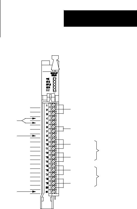
Communication Links |
The 1785-BCM module has ports for three communication links for |
|
connection with the Remote I/O, Data Highway Plus network, and the |
|
other 1785-BCM module (Figure 2.2). In addition, the module has a relay |
|
for customer connection. |
|
As shown in Figure 2.2, there are two user-configurable ports (Channels |
|
1A and 1B) that support remote I/O or Data Highway Plus modes. |
|
Table 2.A lists the communication ports and describes how the system uses |
|
each one. |
2-2
Chapter 2
Understanding the 1785-BCM
Hardware Components
Figure 2.2
1785-BCM Module Communication Links
1 |
|
|
|
Sh |
High Speed Serial Link |
||
2 |
|
|
|
Not Used |
|
|
|
1 |
Customer Relay |
|
|
2 |
|
||
|
|
||
Not Used |
|
|
|
1 |
To Link1 |
|
|
Sh |
|
||
(RIO/DH+) |
|
||
2 |
Channel 1A |
||
|
|||
1 |
From Controller |
(Remote I/O or |
|
Sh |
Data Highway Plus) |
||
2 |
|
|
|
1 |
To Link2 |
|
|
Sh |
|
||
(RIO/DH+) |
|
||
2 |
Channel 1B |
||
|
|||
1 |
|
||
From Controller |
(Remote I/O or |
||
Sh |
Data Highway Plus) |
||
2 |
|
|
|
Not Used |
|
|
|
19082
1Terminals 9, 10, and 11 are connected between the 1785±BCM modules in the backup system; in addition terminals 9, 10, and 11 of one of the 1785 BCM modules are connected to the DH+ network or to the remote I/O link.
2Terminals 15, 16, and 17 are connected between the 1785±BCM modules in the backup system; in addition terminals 15, 16, and 17 of one of the 1785 BCM modules are connected to the DH+ network or to the remote I/O link.
2-3

Chapter 2
Understanding the 1785-BCM
Hardware Components
Table 2.A
Communication Ports
Communication Port: |
This link is used to: |
|
|
|
|
High Speed Serial Link (HSSL) |
permit two-way alternating communication (half-duplex) |
|
between the two 1785-BCM modules of the backup system |
|
at a distance of up to 15 feet. |
|
|
Channel 1A |
connect the primary PLC-5 processor to the Data Highway |
|
Plus network or to the remote I/O link; the secondary |
|
processor is isolated from this link. |
|
|
Channel 1B |
connect the primary PLC-5 processor to the Data Highway |
|
Plus network or to the remote I/O link; the secondary |
|
processor is isolated from this link. |
|
|
Channels 1A and 1B have a default communication mode which can be changed by resetting switches, if necessary. Table 2.B describes the default communication mode for each of the two channels.
Table 2.B
Default Communication Modes
Channel |
Default Communication Mode |
|
|
1A |
Data Highway Plus |
|
|
1B |
Remote I/O ± Scanner mode at 57.6 kbaud |
|
|
With the exception of the HSSL, all of the connections in the 1785-BCM module have an internal relay whose contacts are closed when the controller is primary and open when the processor is secondary. Figure 2.3 shows these relays for processor A and processor B of a PLC-5 backup system.
2-4
Chapter 2
Understanding the 1785-BCM
Hardware Components
Figure 2.3
Relays for Processor A and Processor B
Processor A (primary) |
|
Processor B (secondary) |
|
|
|
|
1785-BCM |
1785-BCM |
|
|
HSSL |
PLC-5 |
DH+ |
PLC-5 |
|
|
Remote I/O |
Customer |
|
|
Relay |
|
|
Processor A (secondary) |
|
Processor B (primary) |
|
1785-BCM |
1785-BCM |
|
|
HSSL |
PLC-5 |
DH+ |
PLC-5 |
|
|
Remote I/O |
Customer |
|
|
Relay |
|
|
11051I
|
|
Important: When using a 1785-BCM module with a PLC-5/40, PLC-5/60, |
|
|
or PLC-5/80 processor, you can add a 1785-BEM backup expansion |
|
|
|
|
|
module to provide backup for all processor communication channels. The |
|
|
channels of the 1785-BEM module, like the 1785-BCM module, can be |
|
|
configured for Data Highway Plus or remote I/O. For more information on |
|
|
the 1785-BEM backup expansion module, refer to Chapter 4. |
|
Customer Relay |
The customer relay connection on the 1785-BCM module is used to switch |
|
|
external devices. Relay contacts are rated at .25A @ 24V dc resistive. |
|
|
Loads with inductive characteristics will require additional suppression |
|
|
devices. |
2-5
Chapter 2
Understanding the 1785-BCM
Hardware Components
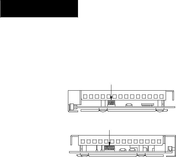
Switch Assemblies |
There are two switch assemblies located at the top and at the bottom of the |
|
1785-BCM module. Refer to Figure 2.4 for locations of the switch |
|
assemblies. Refer to Table 2.C for a description of the function of the |
|
1785-BCM module switch assemblies. |
|
Figure 2.4 |
|
1785-BCM Module Switch Assemblies |
|
Switch Assembly SW1 |
Top View
Switch Assembly SW2
Bottom View
19084
Table 2.C
1785-BCM Module Switch Assembly Functions
Use this switch assembly: |
To: |
|
|
SW1 |
• establish communication between the 1785-BCM |
|
series B module and a 1785-BCM series A module. |
|
• establish the fast data transfer mode from the |
|
secondary module to the secondary processor. |
|
|
SW2 |
• specify if Channels 1A and 1B are going to establish |
|
communication with Data Highway Plus network or |
|
with the remote I/O link. With the remote I/O link, |
|
determine the baud rate as well as the mode of |
|
operation of the processor (scanner or adapter). |
|
|
To set the switches described above, refer to Chapter 5, ªOperating Your
PLC-5 Backup System.º
2-6
|
|
|
|
|
|
|
Chapter 2 |
|
|
|
Understanding the 1785-BCM |
|
|
|
Hardware Components |
I/O Backplane Interface |
|
Through its connection with the I/O chassis backplane, the 1785-BCM |
|
|
|||
|
|
module can execute block transfer read (BTR) and block transfer write |
|
|
|
(BTW) instructions from a PLC-5 processor. With the inherent |
|
|
|
block-transfer queuing capabilities of the PLC-5 processor, multiple |
|
|
|
block-transfer instructions per program scan can be executed to the same |
|
|
|
1785-BCM module. |
|
What to Do Next |
|
This chapter described the hardware components of the 1785-BCM |
|
|
|
module. Now that you are familiar with the module and some of the |
|
|
|
backup concepts for the PLC-5 backup system as described in chapter 1, |
|
|
|
you are ready to install the backup system. Chapters 3 and 4 describes |
|
|
|
installation procedures for the PLC-5 backup system (1785-BCM and |
|
|
|
1785-BEM modules, respectively). |
|
2-7

Chapter Objectives
PLC-5 Backup System
Installation Overview
Chapter 3
Installing Your PLC-5 Backup System
This chapter provides an overview of an installed PLC-5 backup system and describes procedures for installing your PLC-5 backup system (1785-BCM series B module only). These procedures are:
determining power supply requirements setting the I/O chassis switches
setting the module switches installing the 1785-BCM module connecting the PLC-5 backup system
When installing a backup system for a PLC-5/40, PLC-5/60, or PLC-5/80 processor, you may choose to use a 1785-BEM backup expansion module to provide backup for the two additional channels of the processor. Refer to Chapter 4 for installation procedures for the 1785-BEM backup expansion module.
Figure 3.1 shows a typical configuration of a PLC-5 backup system. In this system, communication between the controllers is accomplished through the two 1785-BCM modules. All of the cable connections between the primary and backup system require a 1770-CD (Belden 9463) cable.
Important: Do not install I/O modules for controlling your process in the local chassis. Only the I/O modules residing in the remote chassis will be backed up. Local chassis are necessary for housing the processor, 1785-BCM backup communication module, 1785-BEM backup expansion module, and power supply for the backup system. Local I/O is not
backed up.
When a coprocessor is in the same chassis (standalone mode) or directly connected to a PLC-5 processor (direct-connect mode), place the 1785-BCM and 1785-BEM modules in any other available I/O module group in that chassis
Important: Do not place the 1785-BCM module in the same module group (as defined by 2-slot addressing) as the coprocessor. The 1785-BCM module can reside in an adjacent slot, but not in the same module group (under the same chassis locking tab).
3-1
Chapter 3
Installing Your PLC-5 Backup System
Figure 3.1
PLC-5 Backup System Configuration
|
Local I/O Chassis |
|
|
|
Local I/O Chassis |
|||||||||||||||||
|
1785 ±BCM Module |
|
|
1785 ±BCM Module |
||||||||||||||||||
PLC-5 processor |
|
|
|
|
|
|
|
1771 ±P4S |
PLC-5 processor |
|
|
|
|
|
|
|
|
|
|
|
|
1771 ±P4S |
|
|
|
|
|
|
|
|
|
|
|
|
|
||||||||||
|
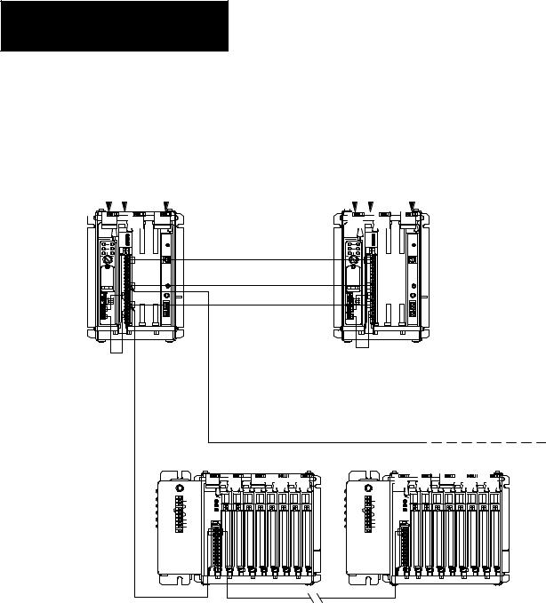
|
|
|
|
|
|
Power Supply |
|
|
|
|
|
|
|
|
|
|
|
|
Power Supply |
||
|
|
|
|
|
|
|
|
|
|
|
|
|
|
|
|
|
|
|
|
|
|
|
|
|
|
|
|
|
|
|
|
|
|
|
|
|
|
|
|
|
|
|
|
|
|
|
|
|
|
|
|
|
|
|
|
|
|
|
|
|
|
|
|
|
|
|
|
|
|
|
|
|
|
|
|
|
|
|
|
|
|
|
|
|
|
|
|
|
|
|
|
|
|
|
|
|
|
|
|
|
|
|
|
|
|
|
|
|
|
|
|
|
|
|
HSSL
Data Highway Plus
Remote I/O
Do not put modules for controlling your process in local I/O chassis.
Remote I/O
To
Data Highway Plus
Network
Remote I/O Chassis |
|
|
|
|
|
Remote I/O Chassis |
|||||||||||||||||||||||||
|
|
|
|
|
|
|
|
|
|
|
|
|
|
|
|
|
|
|
|
|
|
|
|
|
|
|
|
|
|
|
|
Remote I/O
Some applications that use more than two ports (PLC-5/40, PLC-5/60, or PLC-5/80 processors) may require a 1785-BEM module (not shown).
17990
3-2

Determining Power Supply
Requirements
Chapter 3
Installing Your PLC-5 Backup System
The logic circuit of the 1785-BCM module is driven by a power supply through the backplane of the I/O chassis. Determine the power supply requirements for your PLC-5 backup system:
1.Add these values to determine output current needed from the power supply.
1.0A at 5V for a 1785-BCM module and
2.5A for the PLC-5/15 or PLC-5/25 processor or
3.3A for PLC-5/11, -5/20, -5/30, -5/40, -5/60, or -5/80 processor
2.Refer to Table 3.A to choose the power supply that provides sufficient power for all modules in your backup system.
Important: Refer to Chapter 4 to select your power supply when you add a 1785-BEM module in your backup system.
Table 3.A
Power Supplies for a PLC-5 Backup System
Power Supply |
Output Current (in amps) |
Power Supply Location |
|
|
|
|
|
|
1771-P4 |
8 |
slot |
|
|
|
1771-P4R1 |
8 |
slot |
1771-P4S |
8 |
slot |
|
|
|
1771-P4S1 |
8 |
slot |
|
|
|
1771-P5 |
8 |
slot |
|
|
|
1771-P6S |
8 |
slot |
|
|
|
1771-P6S1 |
8 |
slot |
|
|
|
1771-P6R |
8 |
slot |
|
|
|
1771-P7 |
16 |
external2 |
1771-PS7 |
16 |
external2 |
1A P4R redundant power supply can prevent system switchover due to power supply failures or incoming power failures.
2You cannot use an external power supply and a power supply module to power the same chassis; they are not compatible.
3.Use separate power sources for the primary and secondary processors. Connect the power supplies through different power sources to take precautions against interruptions and incoming power failures.
3-3

Chapter 3
Installing Your PLC-5 Backup System
|
Setting the I/O Chassis |
The I/O chassis switch assembly is located on the left side of the chassis |
|
Switches |
backplane. Table 3.B lists the settings we recommend for the local chassis |
|
|
of your PLC-5 backup system. (Local refers to the chassis with the PLC-5 |
|
|
processor and the 1785-BCM module.) You can set remote system |
|
|
switches for your specific application. For more information about setting |
|
|
your I/O chassis backplane switches refer to the Enhanced and Ethernet |
|
|
|
|
|
PLC-5 Programmable Controllers User Manual (publication 1785-6.5.12). |
|
|
Important: The addressing mode and local chassis size you select can |
|
|
affect the number of remote racks available. Refer to the Enhanced and |
|
|
|
|
|
Ethernet PLC-5 Programmable Controllers User Manual (publication |
|
|
1785-6.5.12) for the maximum number of remote racks that can be |
|
|
addressed by the PLC-5 processor(s) in your system. |
Table 3.B
Recommended I/O Chassis Switch Settings for Local Chassis
Set switch(es) |
To this position: |
|
|
|
|
||
1 |
OFF ± to turn off outputs in the chassis when a fault is detected. |
||
|
|
||
2 and 3 |
both OFF ± these switches are not used |
||
|
|
|
|
4 and 5 |
4 |
± ON |
configure for 1/2-slot addressing* |
|
5 |
± OFF |
configure for 1/2-slot addressing* |
|
|
|
|
6 and 7 |
as required for your application |
|
|
|
|
|
|
8 |
as required for your application |
|
|
|
|
|
|
Important: * The 1785-BCM module appears to the PLC-5 processor as a 32-point input module. You must configure switches 4 and 5 for 1/2-slot addressing or 1-slot addressing. If not configured as 1/2- or 1-slot addressing, a PLC-5 processor fault will occur. If you are installing a 1785-BEM module, you must select 1/2-slot addressing.
Terminating the Data Highway
Plus and Remote I/O Links
If your processor is an end device on the Data Highway Plus or remote I/O link, a terminator must be connected to the processor. In the PLC-5 backup system, you should set each PLC-5 processor in the backup system as if the other PLC-5 processor does not exist and no 1785-BCM modules are present. Terminate both links (DH+ and remote I/O):
for a PLC-5/15 or PLC-5/25 processor using switch assembly SW3 on the PLC-5 processor. See Table 3.C.
for a PLC-5/11, -5/20, -5/30, -5/40, -5/60, or -5/80 processor by installing an external resistor on the PLC-5 processor. See Table 3.D.
3-4

Installing the 1785-BCM
Module
Chapter 3
Installing Your PLC-5 Backup System
Table 3.C
Terminate PLC-5/15 or -5/25 Backup System DH+ and Remote I/O Links
Set SW3 |
To this position: |
switch |
|
|
|
1 |
ON ± indicating that the PLC-5 processor is on the end of the remote I/O link |
|
|
1 |
OFF ± indicated that PLC-5 processor is not on the end of the remote I/O link |
|
|
2 |
ON ± indicating that PLC-5 processor is on the end of the DH+ link |
|
|
2 |
OFF ± indicating that PLC-5 processor is not on the end of the DH+ link |
|
|
Table 3.D
Terminate PLC-5/11, -5/20, -5/30, -5/40, -5/60, or -5/80 Backup System DH+ and Remote I/O Links
For this kbaud: |
Install this terminating resistor: |
|
|
57.6 or 115.21 |
150 ohm, 1/2 watt resistor |
230.41 |
82 ohm |
1Refer to the Enhanced and Ethernet PLC-5 Programmable Controllers User Manual to install the terminating resistor.
To install the 1785-BCM module, you:
key the I/O chassis
set the switches of the module insert the module into the chassis
Electrostatic Discharge Damage
ATTENTION: Under some conditions, electrostatic discharge can degrade performance or damage the module. Observe the following precautions to guard against electrostatic damage.
Wear an approved grounded wrist strap or touch a grounded object to discharge potential before handling the module.
Do not touch the backplane connector or connector pins.
If you configure or replace internal components, do not touch other circuit components inside the module. If available, use a static-free work station.
When not in use, keep the module in a static-shielded bag.
3-5
Chapter 3
Installing Your PLC-5 Backup System
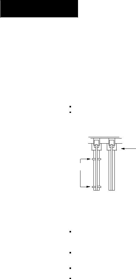
Keying Your I/O Chassis
Use the plastic keying bands, shipped with each I/O chassis, to key the chassis slot to accept only the 1785-BCM module.
The module circuit board is slotted in two places on the rear edge. The position of the keying bands on the backplane connector must correspond to these slots to allow insertion of the module. You can key any connector in an I/O chassis to receive this module except for the left-most connector reserved for the processor modules.
Place keying bands between the following numbers labeled on the backplane connector (Figure 3.2):
Between 8 and 10 |
|
|
|
Between 34 and 36 |
|
|
|
Figure 3.2 |
|
|
|
Keying Positions |
|
|
|
|
2 |
2 |
Backplane Connectors |
|
|
||
|
4 |
4 |
|
|
6 |
6 |
|
|
8 |
8 |
|
|
10 |
10 |
|
|
12 |
12 |
|
Keying bands |
14 |
14 |
|
16 |
16 |
|
|
|
18 |
18 |
|
|
20 |
20 |
|
|
22 |
22 |
|
|
24 |
24 |
|
|
26 |
26 |
|
|
28 |
28 |
|
|
30 |
30 |
|
|
32 |
32 |
|
|
34 |
34 |
11052I |
|
36 |
36 |
|
Setting the 1785-BCM Series B Switch Assemblies
The switch assembly SW1, located at the top of the 1785-BCM module, has four switches as shown in Figure 3.3. Refer to Table 3.E for instructions on setting the four switches. The functions of the four switches are:
Switch 1 indicates to the 1785-BCM series B module whether the other 1785-BCM module is a series A or a series B module. If it is a series A module, functions of switches 2 through 4 will not apply.
Switch 2 selects the Fast Data-Transfer mode from the secondary module to the secondary processor (1785-BCM series B module only).
Switch 3 is not used.
Switch 4 is not used.
3-6

Chapter 3
Installing Your PLC-5 Backup System
The 1785-BCM series B module switch assembly SW1 is preset at the factory to operate:
with another 1785-BCM series B module
in the Fast Data-Transfer mode. Fast data-transfer mode means that when the secondary module receives a data block, it immediately enables it to be read by the secondary processor.
Figure 3.3
1785-BCM Series B Switch Assembly SW1
Switch Assembly SW1
Toggle pushed toward top OFF (open).
Toggle pushed toward bottom ON (closed).
Top View
19085
Table 3.E
Setting 1785-BCM Series B SW1 Switches
When: |
Set this switch: |
To this position: |
|
|
|
|
|
|
|
the other 1785-BCM module is a series A |
11 |
ON (closed) |
|
|
|
|
OFF (opened) |
|
|
|
|
|
|
|
|
|
OFF (opened) |
|
|
|
|
|
|
|
|
|
OFF (opened) |
|
|
|
|
|
|
|
|
21 |
OFF (opened) |
|
|
|
|
|
|
|
|
|
ON (closed) |
|
|
|
|
|
|
|
|
|
ON (closed) |
|
|
|
|
|
|
|
|
|
OFF (opened) |
|
|
|
|
|
|
|
|
|
ON (closed) |
|
|
|
|
|
|
|
|
|
OFF (opened) |
|
|
|
|
|
|
|
the other 1785-BCM module is a series B |
1 |
OFF (opened) |
|
|
|
|
|
|
|
you want fast data transfer |
22 |
ON (closed) |
|
|
|
|
|
|
|
you want the secondary BCM module to enable |
22 |
OFF (opened) |
|
|
BTRs to the secondary PLC-5 processor only |
|
|
|
|
when all blocks of a multi-block segment have |
|
|
|
|
been received |
|
|
|
|
|
|
|
|
|
3-7
Loading...