


 Loading...
Installation Instructions
Ethernet-to-DeviceNet Linking Device
Catalog Number 1788-EN2DN
This publication tells you how to install the 1788-EN2DN
Ethernet-to-DeviceNet linking device and use RSNetWorx™for DeviceNet software to configure it.
Topic |
Page |
|
|
|
|
|
|
Important User Information |
2 |
|
|
|
|
|
|
About the Linking Device |
6 |
|
|
|
|
|
|
System Requirements |
7 |
|
|
|
|
|
|
Installing and Configuring the Linking Device |
8 |
|
|
|
|
|
|
Using Diagnostic Web Pages |
44 |
|
|
|
|
|
|
Dimensions |
49 |
|
|
|
|
|
|
DeviceNet Connector Pinouts |
50 |
|
|
|
|
|
|
EtherNet/IP RJ45 Connector Pinouts |
50 |
|
|
|
|
|
|
Specifications |
51 |
|
|
|
|
|
|
Additional Resources |
55 |
|
|
|
|
|
|
|
|
|
|
|
|
|
|
2 Ethernet-to-DeviceNet Linking Device
Important User Information
Solid-state equipment has operational characteristics differing from those of electromechanical equipment. Safety Guidelines for the Application, Installation and Maintenance of Solid State Controls (publication SGI-1.1 available from your local Rockwell Automation™ sales office or online at http://www.rockwellautomation.com/literature/) describes some important differences between solid-state equipment and hard-wired electromechanical devices. Because of this difference, and also because of the wide variety of uses for solid-state equipment, all persons responsible for applying this equipment must satisfy themselves that each intended application of this equipment is acceptable.
In no event will Rockwell Automation, Inc. be responsible or liable for indirect or consequential damages resulting from the use or application of this equipment.
The examples and diagrams in this manual are included solely for illustrative purposes. Because of the many variables and requirements associated with any particular installation, Rockwell Automation, Inc. cannot assume responsibility or liability for actual use based on the examples and diagrams.
No patent liability is assumed by Rockwell Automation, Inc. with respect to use of information, circuits, equipment, or software described in this manual.
Reproduction of the contents of this manual, in whole or in part, without written permission of Rockwell Automation, Inc., is prohibited.
Throughout this manual, when necessary, we use notes to make you aware of safety considerations.
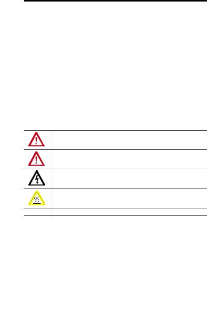
WARNING: Identifies information about practices or circumstances that can cause an explosion in a hazardous environment, which may lead to personal injury or death, property damage, or economic loss.
ATTENTION: Identifies information about practices or circumstances that can lead to personal injury or death, property damage, or economic loss. Attentions help you identify a hazard, avoid a hazard and recognize the consequences.
SHOCK HAZARD: Labels may be on or inside the equipment, for example, drive or motor, to alert people that dangerous voltage may be present.
BURN HAZARD: Labels may be on or inside the equipment, for example, drive or motor, to alert people that surfaces may reach dangerous temperatures.
IMPORTANT Identifies information that is critical for successful application and understanding of the product.
Rockwell Automation Publication 1788-IN055C-EN-P - September 2011

|
|
|
|
|
Ethernet-to-DeviceNet Linking Device 3 |
||
|
|
|
|
|
|
|
|
North American Hazardous Location Approval |
|||||||
|
|
|
|||||
The following information applies when |
Informations sur l’utilisation de cet équipement |
||||||
operating this equipment in hazardous |
en environnements dangereux. |
||||||
locations. |
|
|
|
|
|||
|
|
||||||
Products marked “CL I, DIV 2, GP A, B, C, D” are |
Les produits marqués "CL I, DIV 2, GP A, B, C, D" ne |
||||||
suitable for use in Class I Division 2 Groups A, B, C, D, |
conviennent qu'à une utilisation en environnements de |
||||||
Hazardous Locations and nonhazardous locations |
Classe I Division 2 Groupes A, B, C, D dangereux et non |
||||||
only. Each product is supplied with markings on the |
dangereux. Chaque produit est livré avec des marquages |
||||||
rating nameplate indicating the hazardous location |
sur sa plaque d'identification qui indiquent le code de |
||||||
temperature code. When combining products within |
température pour les environnements dangereux. |
||||||
a system, the most adverse temperature code |
Lorsque plusieurs produits sont combinés dans un |
||||||
(lowest “T” number) may be used to help determine |
système, le code de température le plus défavorable |
||||||
the overall temperature code of the system. |
(code de température le plus faible) peut être utilisé |
||||||
Combinations of equipment in your system are |
pour déterminer le code de température global du |
||||||
subject to investigation by the local Authority |
système. Les combinaisons d'équipements dans le |
||||||
Having Jurisdiction at the time of installation. |
système sont sujettes à inspection par les autorités |
||||||
|
|
|
|
locales qualifiées au moment de l'installation. |
|||
|
|
|
|
|
|
|
|
|
|
|
WARNING: |
|
|
|
AVERTISSEMENT: |
|
|
|
Explosion Hazard - |
|
|
|
Risque d’Explosion – |
|
|
|
• Do not disconnect equipment |
|
|
|
• Couper le courant ou s'assurer que |
|
|
|
|||||
|
|
|
unless power has been removed or |
|
|
|
l'environnement est classé non |
|
|
|
the area is known to be |
|
|
|
dangereux avant de débrancher |
|
|
|
nonhazardous. |
|
|
|
l'équipement. |
|
|
|
• Do not disconnect connections to |
|
|
|
• Couper le courant ou s'assurer que |
|
|
|
this equipment unless power has |
|
|
|
l'environnement est classé non |
|
|
|
been removed or the area is known |
|
|
|
dangereux avant de débrancher les |
|
|
|
to be nonhazardous. Secure any |
|
|
|
connecteurs. Fixer tous les |
|
|
|
external connections that mate to |
|
|
|
connecteurs externes reliés à cet |
|
|
|
this equipment by using screws, |
|
|
|
équipement à l'aide de vis, loquets |
|
|
|
sliding latches, threaded |
|
|
|
coulissants, connecteurs filetés ou |
|
|
|
connectors, or other means |
|
|
|
autres moyens fournis avec ce produit. |
|
|
|
provided with this product. |
|
|
|
• La substitution de composants peut |
|
|
|
• Substitution of components may |
|
|
|
rendre cet équipement inadapté à une |
|
|
|
impair suitability for Class I, |
|
|
|
utilisation en environnement de |
|
|
|
Division 2. |
|
|
|
Classe I, Division 2. |
|
|
|
• If this product contains batteries, |
|
|
|
• S'assurer que l'environnement est |
|
|
|
they must only be changed in an |
|
|
|
classé non dangereux avant de |
|
|
|
area known to be nonhazardous. |
|
|
|
changer les piles. |
|
|
|
|
|
|
|
|
Rockwell Automation Publication 1788-IN055C-EN-P - September 2011
4 Ethernet-to-DeviceNet Linking Device
European Hazardous Location Approval
The following applies when the product bears the Ex Marking.
This equipment is intended for use in potentially explosive atmospheres as defined by European Union Directive 94/9/EC and has been found to comply with the Essential Health and Safety Requirements relating to the design and construction of Category 3 equipment intended for use in Zone 2 potentially explosive atmospheres, given in Annex II to this Directive.
Compliance with the Essential Health and Safety Requirements has been assured by compliance with EN 60079-15 and EN 60079-0.
WARNING: This equipment must be installed in an enclosure providing at least IP54 protection when applied in Zone 2 environments.
This equipment shall be used within its specified ratings defined by Rockwell Automation.
Provision shall be made to prevent the rated voltage from being exceeded by transient disturbances of more than 40% when applied in Zone 2 environments.
Secure any external connections that mate to this equipment by using screws, sliding latches, threaded connectors, or other means provided with this product.
Do not disconnect equipment unless power has been removed or the area is known to be nonhazardous.
ATTENTION: This equipment is not resistant to sunlight or other sources of UV radiation.
Rockwell Automation Publication 1788-IN055C-EN-P - September 2011

Ethernet-to-DeviceNet Linking Device 5
Environment and Enclosure
ATTENTION: This equipment is intended for use in a Pollution Degree 2 industrial environment, in overvoltage Category II applications (as defined in IEC 60664-1), at altitudes up to 2000 m (6562 ft) without derating.
This equipment is considered Group 1, Class A industrial equipment according to IEC/CISPR 11. Without appropriate precautions, there may be difficulties with electromagnetic compatibility in residential and other environments due to conducted and radiated disturbances.
This equipment is supplied as open-type equipment. It must be mounted within an enclosure that is suitably designed for those specific environmental conditions that will be present and appropriately designed to prevent personal injury resulting from accessibility to live parts. The enclosure must have suitable flame-retardant properties to prevent or minimize the spread of flame, complying with a flame spread rating of 5VA, V2, V1, V0 (or equivalent) if non-metallic. The interior of the enclosure must be accessible only by the use of a tool. Subsequent sections of this publication may contain additional information regarding specific enclosure type ratings that are required to comply with certain product safety certifications.
In addition to this publication, see the following:
•Industrial Automation Wiring and Grounding Guidelines, publication 1770-4.1, for additional installation requirements
•NEMA Standard 250 and IEC 60529, as applicable, for explanations of the degrees of protection provided by enclosures
ATTENTION: Prevent Electrostatic Discharge
This equipment is sensitive to electrostatic discharge, which can cause internal damage and affect normal operation. Follow these guidelines when you handle this equipment:
•Touch a grounded object to discharge potential static.
•Wear an approved grounding wriststrap.
•Do not touch connectors or pins on component boards.
•Do not touch circuit components inside the equipment.
•Use a static-safe workstation, if available.
•Store the equipment in appropriate static-safe packaging when not in use.
Rockwell Automation Publication 1788-IN055C-EN-P - September 2011

6 Ethernet-to-DeviceNet Linking Device
About the Linking Device
The 1788-EN2DN Ethernet-to-DeviceNet linking device lets you seamlessly connect your informationor control-level networks with your device-level network.
The linking device provides full DeviceNet master functionality, so you can connect up to 63 DeviceNet slave devices to an Ethernet TCP/IP interface that supports the EtherNet/IP network and an HTTP web server. As examples, you could use the linking device:
•as a gateway to connect informationor control-level networks to device-level networks for programming, configuration, control, or data collection.
•as a router/bridge to connect the EtherNet/IP network to the DeviceNet network.
The linking device provides centralized data storage, or I/O tables, for data shared between the DeviceNet and EtherNet/IP networks. Data is placed into the I/O tables by one network interface, allowing the data to be read through the other network interface.
The linking device appears as a single device on either network by using standard protocol mechanisms. No special, or extended, protocol features are required for the devices on either network to read or write the data flowing through the I/O tables; all cross-network activity is transparent to the devices on either network.
All connections, whether power or fieldbus, to the linking device are made on one end of the module. Phoenix connectors are provided for power and DeviceNet connections. A RJ45 style connector is provided for EtherNet/IP connection.
The linking device can be mounted to a DIN rail.
Rockwell Automation Publication 1788-IN055C-EN-P - September 2011

Ethernet-to-DeviceNet Linking Device 7
System Requirements
The following hardware and software components are required to use the linking device.
Required Hardware
•1788-EN2DN linking device
•DeviceNet cabling, power, and devices forming a DeviceNet network
•Ethernet cabling and power
•Computer with access to the Ethernet network
•Computer running DeviceNet configuration software
The DeviceNet slave devices with which the linking device communicates are specified using a DeviceNet Configuration Software tool such as RSNetWorx for DeviceNet software.
•24V DC power to the linking device
DeviceNet power may be used; however, using DeviceNet power bypasses the DeviceNet network isolation.
Required Software
•DeviceNet configuration software, such as RSNetWorx for DeviceNet software, version 4.01 or later, to configure DeviceNet devices and the linking device’s DeviceNet functionality
•RSLinx® software, version 2.31 or later
•DHCP server 2.3.2 or later, which ships with RSLinx software version
2.42 and later. If you are using an earlier version of RSLinx software, you will need to download the standalone server from http://www.rockwellautomation.com/support
Rockwell Automation Publication 1788-IN055C-EN-P - September 2011

8 Ethernet-to-DeviceNet Linking Device
Optional Software
RSLogix™ 5000 software, version 13 or later.
Installing and Configuring the Linking Device
WARNING: If you connect or disconnect the communication cable with power applied to this module or any device on the network, an electrical arc can occur. This could cause an explosion in hazardous location installations.
If you connect or disconnect wiring while the field-side power is on, an electrical arc can occur. This could cause an explosion in hazardous location installations. Be sure that power is removed or the area is nonhazardous before proceeding.
When you change switch settings while field-side power is on, an electrical arc can occur. This could cause an explosion in hazardous location installations.
Be sure that power is removed or the area is nonhazardous before proceeding.
Follow these steps to install the linking device (described in the sections that follow).
Rockwell Automation Publication 1788-IN055C-EN-P - September 2011

Ethernet-to-DeviceNet Linking Device 9
Connect the Linking Device to the EtherNet/IP Network
Connect the EtherNet/IP network cable to the RJ45 port on the end of the linking device.
DeviceNet Connection
Power Connection
Configuration DIP Switch
31480-M
RJ45 Port (EtherNet/IP Connection)
ATTENTION: This product is grounded through the DIN rail to chassis ground. Use zinc plated yellow-chromate steel DIN rail to assure proper grounding. The use of other DIN rail materials (for example, aluminum or plastic) that can corrode, oxidize, or are poor conductors, can result in improper or intermittent grounding. Secure DIN rail to mounting surface approximately every 200 mm (7.8 in.) and use end-anchors appropriately.
Rockwell Automation Publication 1788-IN055C-EN-P - September 2011
10 Ethernet-to-DeviceNet Linking Device
Connect the Linking Device to the DeviceNet Network
ATTENTION:
Do not wire more than 2 conductors on any single terminal.
To comply with the CE Low Voltage Directive (LVD), this equipment must be powered from a source compliant with Safety Extra Low Voltage (SELV) or Protected Extra Low Voltage (PELV).
To comply with UL restrictions, this equipment must be powered from a source compliant with Class 2 or Limited Voltage/Current.
1.Make sure a computer running RSNetWorx for DeviceNet software is connected to the EtherNet/IP network.
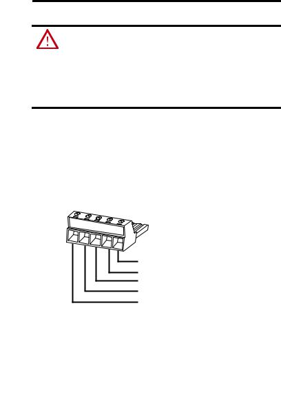
2.With power to the linking device off, connect the DeviceNet network cable to the DeviceNet connector on the linking device.
The female terminal block connector is provided with the linking device.
(Red) Net Power 24V DC
(White) CAN High +
CAN Shield
(Blue) CAN Low
(Black) Net Power 24V DC Common 31442-M
3.Connect the power cable to the linking device.
The female terminal block connector is provided with the linking device.
Rockwell Automation Publication 1788-IN055C-EN-P - September 2011
Ethernet-to-DeviceNet Linking Device 11
..
|
|
|
|
|
24V DC common |
|
|
|
|
|
|
|
|
|
|
|
|
|
|
|
|
|
24V DC + |
|
|
|
|
||
TIP |
Two 120 ohm termination resistors (supplied with the linking device) may be |
||||
|
required for proper network termination at each end of the trunk line. See the |
||||
|
DeviceNet Specification (available from the Open DeviceNet Vendors |
||||
|
Association at http://www.odva.org) for specific rules on DeviceNet |
||||
|
connections and termination. |
||||
4. Apply power to the linking device and DeviceNet network.
IMPORTANT |
The linking device defaults to Autobaud. This means that the linking device |
|
automatically finds the network communication rate at when power is |
|
applied. You must specify a master device, such as a DeviceNet Bridge Module |
|
(catalog number 1756-DNB) so that the linking device can pick up the correct |
|
communication rate. If you do not have another device installed, you must |
|
use RSNetWorx for DeviceNet software to set the communication rate, as |
|
described in Set the DeviceNet MAC ID and Communication Rate on page 21. |
|
Do not attempt to commission the linking device on a network configured at |
|
a different communication rate. |
|
|
Rockwell Automation Publication 1788-IN055C-EN-P - September 2011

12 Ethernet-to-DeviceNet Linking Device
Configure the Linking Device IP Address
Several methods may be used to set the IP Address. These methods include the following:
•IP address configuration DIP switch
•DHCP protocol
•Web page
•RSLogix 5000 software, version 13 or later), and 1788-EN2DN Linking Device, revision 2.x or later
Setting the IP Address with the Configuration DIP Switch
A configuration DIP switch on the end of the linking device lets you set the IP address. If the configuration DIP switch is set to 1 (in the up position, as shown in the following figure), when power is applied to the switch, the value of the switch creates the IP address of 192.168.1.1.
IMPORTANT |
The numbers that appear above the switches on the DIP switch do not |
|
correspond to bit locations in the address value. The numbers on the switch |
|
are opposite the address value bit locations; for example, bit 0 is set by |
|
switch 8. |
|
|
IP Address Configuration DIP Switch
|
|
|
|
|
|
|
ON |
8 |
7 |
6 |
5 |
4 |
3 |
2 |
1 |
8 7 6 5 4 3 2 1 ON
31421-M
Rockwell Automation Publication 1788-IN055C-EN-P - September 2011
Ethernet-to-DeviceNet Linking Device 13
The switch represents the binary value of the last byte in the 4-byte IP address. In this case it is n. If n = 0, the linking device obtains its IP address from the software configuration (DHCP or web page).
IP address |
192.168.1.n |
|
|
Subnet mask |
255.255.255.0 |
|
|
Gateway address |
0.0.0.0 (No gateway set) |
|
|
Setting the IP Address By Using DHCP/BootP
TIP |
The use of DHCP is the default configuration for the linking device as shipped. |
|
The IP address configuration DIP switch ships with n =0. |
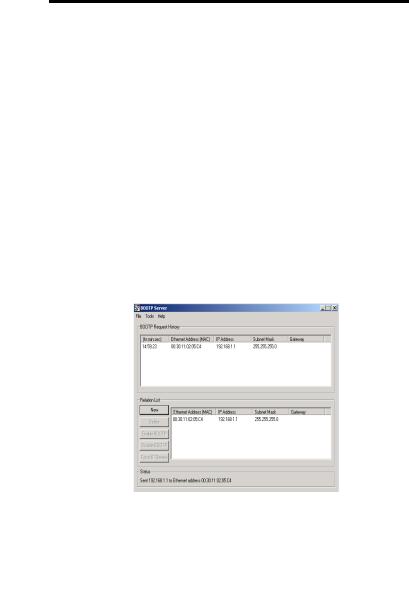
When DHCP/BootP is enabled and a DHCP or BootP server is found, the IP address, Subnet mask, and Gateway address are automatically configured by the DHCP server, as shown in the following figure.
Automatic Configuration
Follow these steps to change the IP address, Subnet mask, and Gateway address from this dialog box.
Rockwell Automation Publication 1788-IN055C-EN-P - September 2011
14Ethernet-to-DeviceNet Linking Device
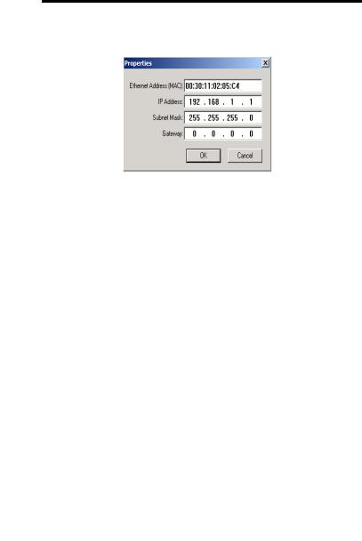
1.Click New.
You see the Properties dialog box.
2.On the Properties dialog box, enter the appropriate values into the following fields.
•Ethernet address (MAC ID) [from the linking device product ID label]
•IP address
•Subnet Mask
•Gateway (IP address)
3.Click OK.
Rockwell Automation Publication 1788-IN055C-EN-P - September 2011
Ethernet-to-DeviceNet Linking Device 15
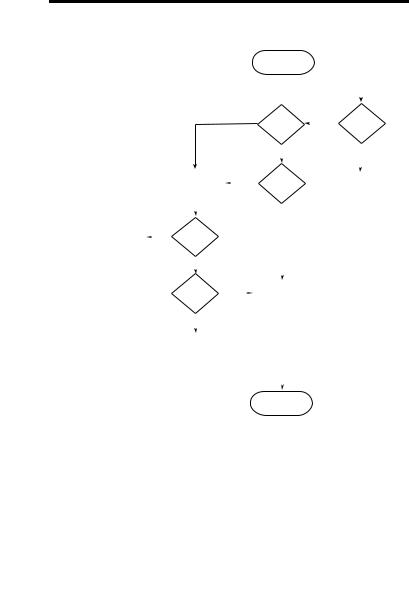
The following figure shows a flowchart describing how the IP configuration is determined when the linking device is powered up.
|
|
|
|
|
|
|
|
|
|
|
|
Start |
|
|
|
|
||
|
|
|
|
|
|
|
|
|
|
|
|
|
|
|
|
|
|
|
|
|
|
|
|
|
|
|
|
|
|
|
|
|
|
|
|
|
|
|
|
|
|
|
|
|
|
|
|
|
|
Valid |
|
|
|
|
||
|
|
|
|
|
|
No |
|
|
|
|
Yes |
|||||||
|
|
|
|
|
|
|
|
|
|
Configuration |
||||||||
|
|
|
|
|
|
|
|
|
|
|
|
|
|
|
|
|
DIP Switch = 0 |
|
|
|
|
|
|
|
|
|
|
|
|
|
in Flash Memory? |
|
|
||||
|
|
|
|
|
|
|
|
|
|
|
|
|
|
|
|
|||
|
|
|
|
|
|
|
|
|
|
|
|
|
|
|
|
|
|
|
|
|
|
|
|
|
|
|
|
|
|
|
Yes |
|
|
|
|
No |
|
|
|
|
|
|
|
|
|
|
|
|
|
|
|
|
|
|
|
|
|
|
|
|
|
|
|
|
|
|
|
|
|
|
|
|
|
|
|
|
|
|
|
|
Request config |
|
Yes |
|
|
|
|
|
|
|
|
|||
|
|
|
|
|
from DHCP/ |
|
|
DHCP |
|
|
IP = 192 168.1.n |
|||||||
|
|
|
|
|
BOOTP Server. |
|
|
|
|
Enabled? |
|
Sub = 255.255.255.0 |
||||||
|
|
|
|
|
Timeout 30 secs |
|
|
|
|
|
|
|
|
|
No Gateway |
|||
|
|
|
|
|
|
|
|
|
|
|
|
|
|
|
|
|
|
|
|
|
|
|
|
|
|
|
|
|
|
|
|
|
|
|
|
|
|
|
|
|
Yes |
|
DHCP |
|
|
|
|
No |
|
|
|
|
|
|
||
Use received |
|
|
|
|
|
|
|
|
|
|
|
|
||||||
|
|
|
Config |
|
|
|
|
|
|
|
|
|
|
|
||||
configuration |
|
|
|
|
|
|
|
|
|
|
|
|
|
|
||||
|
|
|
Received? |
|
|
|
|
|
|
|
|
|
|
|
||||
|
|
|
|
|
|
|
|
|
|
|
|
|
|
|
|
|||
|
|
|
|
|
|
|
|
|
|
|
|
|
|
|
|
|
|
|
|
|
|
|
|
No |
|
|
|
|
|
|
|
|
|
|
|
|
|
|
|
|
|
|
|
|
|
|
|
|
|
|
|
|
|
|
|
|
|
|
|
|
|
|
|
|
|
|
|
|
|
|
|
|
|
|
|
|
|
|
|
|
Valid |
Yes |
|
|
|
|
|
|
|
|
|
|
||
|
|
|
|
|
|
|
|
|
|
|
|
|
|
|
||||
|
|
|
|
|
|
|
|
Use Valid (stored) |
|
|
|
|
||||||
|
|
|
|
|
Configuration |
|
|
|
|
|
|
|
|
|
||||
|
|
|
|
|
|
|
|
|
|
IP address |
|
|
|
|
||||
|
|
|
|
|
File? |
|
|
|
|
|
|
|
|
|||||
|
|
|
|
|
|
|
|
|
|
|
|
|
|
|
|
|||
|
|
|
|
|
|
|
|
|
|
|
|
|
|
|
|
|
|
|
|
|
|
|
|
|
|
|
|
|
|
|
|
|
|
|
|
|
|
|
|
|
|
|
No |
|
|
|
|
|
|
|
|
|
|
|
|
|
|
|
|
|
|
|
|
|
|
|
|
|
|
|
|
|
|
|
|
|
|
|
|
|
|
|
|
|
|
|
|
|
|
|
|
|
|
|
|
|
|
|
|
Remain offline |
|
|
|
|
|
|
|
|
|
|
|
||
|
|
|
|
|
|
|
|
|
|
|
|
|
|
|
|
|
|
|
|
|
|
|
|
|
|
|
|
|
|
|
|
|
|
|
|
|
|
|
|
|
|
|
|
|
|
|
|
|
|
|
|
|
|
|
|
|
|
|
|
|
|
|
|
|
|
|
|
|
|
|
|
|
|
|
|
|
Stop |
31445-M |
TIP |
You can enable these values using the linking device’s IP Configuration web |
|
|
page. Refer to Setting the IP Address Using By Using the Web Page on |
|
|
page 16. |
|
Rockwell Automation Publication 1788-IN055C-EN-P - September 2011
16 Ethernet-to-DeviceNet Linking Device
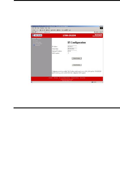
Setting the IP Address Using By Using the Web Page
The EtherNet/IP address can also be configured using the IP Configuration web page on the linking device, as shown in the following figure.
The IP address can be set with the web page only if the linking device already has a valid IP address. Typically, you can do this by using the DIP switch to force the linking device to use a temporary IP address after you cycle power. Follow these steps to configure the IP address with the web page.
IMPORTANT |
Because the DIP switch setting overrides other IP address configurations, be |
|
sure to set the DIP switch to the 0 position before continuing. |
|
|
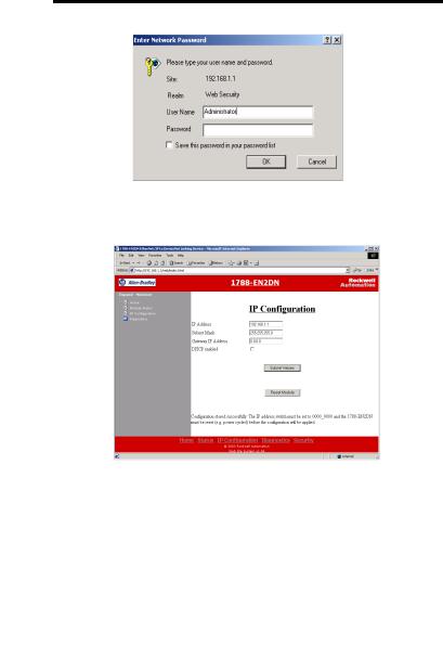
1.Browse to the linking device by entering the temporary IP address in your web browser’s address bar and click Enter.
2.In the left pane, click IP Configuration.
You see the Enter Network Password dialog box.
3.In the Username field, enter Administrator.
Rockwell Automation Publication 1788-IN055C-EN-P - September 2011
Ethernet-to-DeviceNet Linking Device 17
4. Leave the password field blank.
5.Click OK.
You see the IP Configuration dialog box.
Rockwell Automation Publication 1788-IN055C-EN-P - September 2011
Loading...