


1784-PKTX
Table of contents
 Loading...
1784-PKTx
Network Interface
Card
1784-PKTX, -PKTXD
User Manual
Important User Information
Solid state equipment has operational characteristics differing from those of electromechanical equipment.
Safety Guidelines for the Application, Installation and Maintenance of Solid State Controls (Publication
SGI-1.1 available from your local Rockwell Automation sales office or online at
http://www.ab.com/manuals/gi) describes some important differences between solid state equipment and
hard-wired electromechanical devices. Because of this difference, and also because of the wide variety of
uses for solid state equipment, all persons responsible for applying this equipment must satisfy themselves
that each intended application of this equipment is acceptable.
In no event will Rockwell Automation, Inc. be responsible or liable for indirect or consequential damages
resulting from the use or application of this equipment.
The examples and diagrams in this manual are included solely for illustrative purposes. Because of the many
variables and requirements associated with any particular installation, Rockwell Automation, Inc. cannot
assume responsibility or liability for actual use based on the examples and diagrams.
No patent liability is assumed by Rockwell Automation, Inc. with respect to use of information, circuits,
equipment, or software described in this manual.
Reproduction of the contents of this manual, in whole or in part, without written permission of Rockwell
Automation, Inc. is prohibited.
Throughout this manual we use notes to make you aware of safety considerations.
WARNING
Identifies information about practices or circumstances that can cause an explosion in a
hazardous environment, which may lead to personal injury or death, property damage,
or economic loss.
IMPORTANT
ATTENTION
SHOCK HAZARD
BURN HAZARD
Identifies information that is critical for successful application and understanding of the
product.
Identifies information about practices or circumstances that can lead to personal injury
or death, property damage, or economic loss. Attentions help you:
• identify a hazard
• avoid a hazard
• recognize the consequence
Labels may be located on or inside the drive to alert people that dangerous voltage may
be present.
Labels may be located on or inside the drive to alert people that surfaces may be
dangerous temperatures.

Preface
Introduction
This manual describes how to install, configure, and troubleshoot the 1784-PKTX and
-PKTXD network interface cards. Throughout the manual, we refer to this product as the
PKTx card. When one card differs from the other, this document individually calls out the
cards by name.
Contents of Your Package
With this package you should receive:
• one 1784-PKTx network interface card
• one 1784-PKTx Network Interface Card User Manual, publication
1784-UM527B-EN-P
If you are missing any of these pieces, contact your Allen-Bradley distributor.
Abbreviations
Throughout this manual, we abbreviate some terms. Use this table to become familiar with
our terminology.
This is the abbreviation for
BIOS Basic Input/Output System
ESD Electrostatic Discharge
IRQ Interrupt Request
ISA Industry-Standard Architecture
NIC Network Interface Card
ORB Outside Retaining Bracket
PCI Peripheral Component Interconnect
PC Personal Computer
RIO Remote I/O
Publication 1784-UM527B-EN-P - October 2003

2 Preface
Conventions
We use these conventions in this manual:
• Screen displays and prompts are shown as
Press ENTER to continue with the installation
• Text that you type is shown as:
a:\install c
• Keys that you press look like this:
• Other actions to be performed are show as:
Click on the Memory tab.
Enter
Publication 1784-UM527B-EN-P - October 2003

Environment and Enclosure
Preface 3
ATTENTION
This equipment is intended for use in a Pollution Degree 2 industrial
environment, in overvoltage Category II applications (as defined in IEC
publication 60664-1), at altitudes up to 2000 meters without derating.
This equipment is considered Group 1, Class A industrial equipment
according to IEC/CISPR Publication 11. Without appropriate
precautions, there may be potential difficulties ensuring electromagnetic
compatibility in other environments due to conducted as well as radiated
disturbance.
This equipment is supplied as “open type” equipment. It must be
mounted within an enclosure that is suitably designed for those specific
environmental conditions that will be present and appropriately designed
to prevent personal injury resulting from accessibility to live parts. The
interior of the enclosure must be accessible only by the use of a tool.
Subsequent sections of this publication may contain additional
information regarding specific enclosure type ratings that are required to
comply with certain product safety certifications.
NOTE: See NEMA Standards publication 250 and IEC publication
60529, as applicable, for explanations of the degrees of protection
provided by different types of enclosure. Also, see the appropriate
sections in this publication, as well as the Allen-Bradley publication
1770-4.1 (“Industrial Automation Wiring and Grounding Guidelines”),
for additional installation requirements pertaining to this equipment.
Preventing Electrostatic Discharge
ATTENTION
This equipment is sensitive to electrostatic discharge, which can cause
internal damage and affect normal operation. Follow these guidelines
when you handle this equipment:
• Touch a grounded object to discharge potential static.
• Wear an approved grounding wriststrap.
• Do not touch connectors or pins on component boards.
• Do not touch circuit components inside the equipment.
• If available, use a static-safe workstation.
• When not in use, store the equipment in appropriate static-safe
packaging.
Publication 1784-UM527B-EN-P - October 2003
4 Preface
North American Hazardous Location Approval
The following information applies when
operating this equipment in hazardous locations:
Products marked “CL I, DIV 2, GP A, B, C, D” are
suitable for use in Class I Division 2 Groups A, B, C, D,
Hazardous Locations and nonhazardous locations only.
Each product is supplied with markings on the rating
nameplate indicating the hazardous location
temperature code. When combining products within a
system, the most adverse temperature code (lowest
“T” number) may be used to help determine the overall
temperature code of the system. Combinations of
equipment in your system are subject to investigation
by the local Authority Having Jurisdiction at the time
of installation.
WARNING
EXPLOSION HAZARD
• Do not disconnect
equipment unless power
has been removed or the
area is known to be
nonhazardous.
• Do not disconnect
connections to this
equipment unless power
has been removed or the
area is known to be
nonhazardous. Secure any
external connections that
mate to this equipment by
using screws, sliding
latches, threaded
connectors, or other
means provided with this
product.
• Substitution of
components may impair
suitability for Class I,
Division 2.
• If this product contains
batteries, they must only
be changed in an area
known to be
nonhazardous.
Informations sur l’utilisation de cet équipement
en environnements dangereux:
Les produits marqués "CL I, DIV 2, GP A, B, C, D" ne
conviennent qu’à une utilisation en environnements
de Classe I Division 2 Groupes A, B, C, D dangereux et
non dangereux. Chaque produit est livré avec des
marquages sur sa plaque d’identification qui
indiquent le code de température pour les
environnements dangereux. Lorsque plusieurs
produits sont combinés dans un système, le code de
température le plus défavorable (code de température
le plus faible) peut être utilisé pour déterminer le
code de température global du système. Les
combinaisons d’équipements dans le système sont
sujettes à inspection par les autorités locales
qualifiées au moment de l’installation.
AVERTISSEMENT
RISQUE D’EXPLOSION
• Couper le courant ou
s’assurer que
l’environnement est
classé non dangereux
avant de débrancher
l'équipement.
• Couper le courant ou
s'assurer que
l’environnement est
classé non dangereux
avant de débrancher les
connecteurs. Fixer tous
les connecteurs
externes reliés à cet
équipement à l'aide de
vis, loquets coulissants,
connecteurs filetés ou
autres moyens fournis
avec ce produit.
• La substitution de
composants peut rendre
cet équipement
inadapté à une
utilisation en
environnement de
Classe I, Division 2.
• S’assurer que
l’environnement est
classé non dangereux
avant de changer les
piles.
Publication 1784-UM527B-EN-P - October 2003

Table of Contents
Chapter 1
Introducing the Network Interface Cards
How the 1784-PKTx Card Operates . . . . . . . . . . . . . . . . . . . . . . . . . . . . . 1-2
Chapter 2
Configuring the PKTx Hardware
Introduction . . . . . . . . . . . . . . . . . . . . . . . . . . . . . . . . . . . . . . . . . . . . . . . . . 2-1
Interrupt Request Assignment. . . . . . . . . . . . . . . . . . . . . . . . . . . . . . . . . . . 2-1
Base Memory Address Values . . . . . . . . . . . . . . . . . . . . . . . . . . . . . . . . . . 2-1
Setting a Base Memory Address Jumper . . . . . . . . . . . . . . . . . . . . . . 2-2
Using Multiple PKTx Cards . . . . . . . . . . . . . . . . . . . . . . . . . . . . . . . . . . . . 2-3
Planning Jumper Settings for Multiple Cards . . . . . . . . . . . . . . . . . . . 2-4
What to Do Next . . . . . . . . . . . . . . . . . . . . . . . . . . . . . . . . . . . . . . . . . . . . . 2-4
Chapter 3
Installing the Card and the Drivers
Accessing the PCI Bus Slots and Installing the Card. . . . . . . . . . . . . . . . . 3-1
Installing the Plug and Play Drivers . . . . . . . . . . . . . . . . . . . . . . . . . . . . . . 3-2
What to Do Next . . . . . . . . . . . . . . . . . . . . . . . . . . . . . . . . . . . . . . . . . . . . . 3-2
Chapter 4
Connecting the Network Interface Card
1784-PKTX Connections . . . . . . . . . . . . . . . . . . . . . . . . . . . . . . . . . . . . . . 4-2
1784-PKTXD Connections. . . . . . . . . . . . . . . . . . . . . . . . . . . . . . . . . . . . . 4-3
Before You Begin. . . . . . . . . . . . . . . . . . . . . . . . . . . . . . . . . . . . . . . . . . . . . 4-4
Connecting to DH+ Devices . . . . . . . . . . . . . . . . . . . . . . . . . . . . . . . . . . . 4-5
Connecting the Card to
an Original PLC-5 Programmable Controller . . . . . . . . . . . . . . . . . . . 4-5
Connecting the Card to an Enhanced PLC-5 Processor. . . . . . . . . . . 4-7
Terminating the Last Node . . . . . . . . . . . . . . . . . . . . . . . . . . . . . . . . . 4-7
Connecting the Card Using Custom Cabling for DH+ . . . . . . . . . . 4-8
Connecting the Card via a DH-485 Network. . . . . . . . . . . . . . . . . . . . . . . 4-8
Connecting the Card to a Single SLC Processor on DH-485. . . . . . . 4-9
Terminating the Last Node . . . . . . . . . . . . . . . . . . . . . . . . . . . . . . . . 4-11
Connecting to Remote I/O Devices. . . . . . . . . . . . . . . . . . . . . . . . . . . . . 4-11
Publication 1784-UM527B-EN-P - October 2003

ii Table of Contents
Interpreting the Status LEDs . . . . . . . . . . . . . . . . . . . . . . . . . . . . . . . . . . 4-12
What to Do Next . . . . . . . . . . . . . . . . . . . . . . . . . . . . . . . . . . . . . . . . . . . . 4-13
Appendix A
Specifications
Index
Publication 1784-UM527B-EN-P - October 2003

Chapter
1
Introducing the Network Interface Cards
Rockwell Automation 1784-PKTx family PCI cards connect PCs to PLC controllers on Data
Highway Plus (DH+) or SLC processors on DH-485 networks for easy programming and
data acquisition. I/O scanner functionality is also available in the cards so they can be used
with soft-control or embedded-control engines. And, because these cards incorporate the
Universal PCI Card Standard, they are compatible with almost any PC. If general
programming, configuration, and monitoring capabilities via an industrial or desktop PC are
required, these cards are a necessity.
Your 1784-PKTx network interface card (cat. nos. 1784-PKTX and 1784-PKTXD) is a PCI
(Peripheral Component Interconnect) universal card that must be inserted into a PCI bus
slot. A universal card can be placed into a PCI bus slot that is keyed for either 3.3 Volt or 5
Volt signalling. This card may also be placed in a 64-bit slot, although it will not use the
extended 64-bit operation.
Table 1.1 Features supported by PKTx cards
Table 1.1 outlines features supported by the PKTx cards.
KTx card
catalog #
1784-PKTX 1
1784-PKTXD 2
!
Available only on channel 1
# of
channels
Active node
on these
networks
DH+ or
DH-485
DH+ and/or
!
DH-485
Remote I/O
scanner
capability?
yes
yes
Publication 1784-UM527B-EN-P - October 2003

1-2 Introducing the Network Interface Cards
Compatibility
You need a PCI-compatible personal computer. Table 1.2 outlines operating systems and
drivers that support the PKTx cards.
Table 1.2 Operating Systems and drivers supporting the PKTx cards
Windows 98 or later Other operating system
DH+ Included with RSLinx
DH-485 Included with RSLinx Same as DH+
Remote I/O
Write your own driver using
6001-RIO - RIO Tool Kit
Write your own driver using
1784-DP4
Write your own driver using
6001-RIO - RIO Tool Kit
How the 1784-PKTx Card Operates
The 1784-PKTX and -PKTXD cards:
• communicate with nodes on Data Highway Plus networks, including PLC-5®,
PLC-5/250, and SLC 5/04 processors, and SLC 5/01,
SLC 5/02, and SLC5/03 processors (only via 1785-KA5)
• communicate with SLC processors on DH-485 networks
• communicate to DH+ and Remote I/O via SoftLogix-5
• communicate to ControlLogix through a 1756-DHRIO module
• act as a remote I/O scanner
The 1784-PKTx performs data transmission, management, and local network diagnostics.
The interface to the host processor is through a board-resident dual-port memory.
Rockwell Automation RSLinx interface software manages data transmission and reception
through dual-port memory.
The PCI BIOS on your computer automatically assigns the PKTx card’s IRQ and base
memory address (one for each channel). If your card has two channels, both channels share
the same IRQ.
Publication 1784-UM527B-EN-P - October 2003

Chapter
2
Configuring the PKTx Hardware
Introduction
The 1784-PKTx card is a PCI bus card, compliant with the PCI Bus Specification Revision
2.3. This card was developed with Plug and Play functionality, as defined in Revision 1.0A of
the Plug and Play BIOS Specification. Because of this, PKTx cards do not require the use of
switches or jumpers to configure their specific interrupt request levels (IRQ) and base
memory address values. These configurations are automatically assigned to the PKTx card by
the PCI BIOS when the computer is powered-up. The configurations are stored in the PCI
configuration registers. These values may be retrieved by application software used to
communicate with the PKTx card.
Interrupt Request Assignment
The PCI BIOS automatically assigns the PKTx card an IRQ. Because of this, each time you
add or remove cards and restart your computer, the BIOS may assign a different IRQ to each
card. You should check the IRQ assignment each time you start your system. Most
application software will verify this assignment for you. If you’re using RSLinx, its Plug and
Play driver verifies the IRQ.
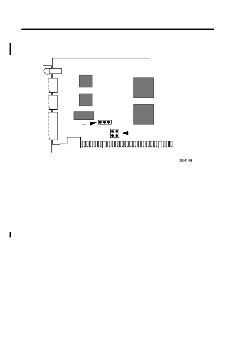
Base Memory Address Values
Although the assignment of the IRQ and base memory address values is automatic, and does
not require user intervention, there is one jumper on the PKTx card that is used to restrict the
range of values that can be assigned to the base memory address by the PCI BIOS. This
jumper is called the Base Memory Address jumper, and its default position is set to 32 bit.
you are not using Microsoft Windows 95 or later, you may have to set this jumper. See
If
Figure 2.1 on page 2-2.
Publication 1784-UM527B-EN-P - October 2003
2-2 Configuring the PKTx Hardware
Figure 2.1 Overview of the jumpers on the PKTx card
Base Memory
Jumper (JP2)
Card ID Jumper (JP3)
Setting a Base Memory Address Jumper
The host computer and the PKTx card exchange data via a dual-port interface. The dual-port
requires 4 Kbytes of memory. This 4 Kbyte block of memory begins at the base memory
address assigned to the card by the PCI BIOS when the computer is started.
Under MS-DOS, Windows 3.1 and Windows for Workgroups, the base memory address of
PC cards should fall within the range of 0 and 1 Megabyte of PC memory. For the newer
Windows operating systems, this restriction is no longer required, and the base memory
address should be located anywhere in the PC memory space.
The Base Memory Address jumper (JP2) forces the PCI BIOS to assign the base memory
address to one of two address ranges, as shown in the table below. You should select the
jumper position based on the operating system running on your PC.
Publication 1784-UM527B-EN-P - October 2003
Loading...