


 Loading...
Allen-Bradley
PLC-5 VME
VMEbus
Programmable
Controllers
(1785-V30B, -V40B, -V40L, and -V80B)
User
Manual

Important User Information |
Because of the variety of uses for the products described in this publication, those |
|
||
|
responsible for the application and use of this control equipment must satisfy |
|
||
|
themselves that all necessary steps have been taken to ensure that each application |
|
||
|
and use meets all performance and safety requirements, including any applicable |
|
||
|
laws, regulations, codes and standards. |
|
||
|
The illustrations, charts, sample programs and layout examples shown in this guide |
|
||
|
are intended solely for purposes of example. Since there are many variables and |
|
||
|
requirements associated with any particular installation, Allen-Bradley does not |
|
||
|
assume responsibility or liability (to include intellectual property liability) for |
|
||
|
actual use based on the examples shown in this publication. |
|
||
|
Allen-Bradley publication SGI-1.1, Safety Guidelines for the Application, |
|
||
|
Installation, and Maintenance of Solid State Control (available from your local |
|
||
|
Allen-Bradley office), describes some important differences between solid-state |
|
||
|
equipment and electromechanical devices that should be taken into consideration |
|
||
|
when applying products such as those described in this publication. |
|
||
|
Reproduction of the contents of this copyrighted publication, in whole or in part, |
|
||
|
without written permission of Allen-Bradley Company, Inc., is prohibited. |
|
||
|
Throughout this manual we use notes to make you aware of safety considerations: |
|
||
|
|
|
|
|
|
|
|
ATTENTION: Identifies information about practices or |
|
|
|
|
circumstances that can lead to personal injury or death, |
|
|
|
|
property damage, or economic loss. |
|
|
|
|
|
|
|
|
|
Attention statements help you to: |
|
|
|
|
identify a hazard |
|
|
|
|
avoid the hazard |
|
|
|
|
recognize the consequences |
|
|
|
|
Important: Identifies information that is critical for successful application and |
|
|
|
|
understanding of the product. |
|

Table of Contents
Summary of Changes . . . . . . . . . . . . . . . . . . . . . . . . . . . . |
|
|
i |
|
. . . . . . . . . . . . . . . . . . . . . . . . . . . . . . .Using this Manual |
|
iii |
||
Manual Objectives . . . . . . . . . . . . . . . . . . . . . . . . . . . . . . . . . . . |
|
iii |
||
What this Manual Contains . . . . . . . . . . . . . . . . . . . . . . . . . . . . . |
|
iii |
||
Audience . . . . . . . . . . . . . . . . . . . . . . . . . . . . . . . . . . . . . . . . . |
|
iii |
||
Terms and Conventions . . . . . . . . . . . . . . . . . . . . . . . . . . . . . . . |
|
iv |
||
Related Publications . . . . . . . . . . . . . . . . . . . . . . . . . . . . . . . . . |
|
|
v |
|
Overview . . . . . . . . . . . . . . . . . . . . . . . . . . . . . . . . . . . . . . |
1-1 |
|||
Chapter Objectives . . . . . . . . . . . . . . . . . . . . . . . . . . . . . . . . . . |
|
1-1 |
||
. . . . . . . . . . . . . . . . . . . . . . . . . . . . . . . . . . . . . . . . . .Features |
|
1-1 |
||
. . . . . . . . . . . . . . . . . . . . . . . . . . . . . . . . . .System Description |
|
1-4 |
||
. . . . . . . . . . . . . . . . . . . . . . . . . . . . . . . . . . .VMEbus Interface |
|
1-6 |
||
. . . . . . . . . . . . .Compatibility with the Standard PLC-5 Processor |
|
1-9 |
||
. . . . . . . . . . . . . . . . .Compatibility with the 6008-LTV Processor |
|
1-9 |
||
Installation . . . . . . . . . . . . . . . . . . . . . . . . . . . . . . . . . . . . . |
2-1 |
|||
Chapter Objectives . . . . . . . . . . . . . . . . . . . . . . . . . . . . . . . . . . |
|
2-1 |
||
. . . . . . . . . . . . . . . . . . . . . . . . . . . . . . .Handling the Processor |
|
2-2 |
||
. . . . . . . . . . . . . . . . . . . . . . . . . . . . . . . . .Setting the Switches |
|
2-2 |
||
. . . . . . . . . . . . . . . . . .Configuring the VME Backplane Jumpers |
|
2-4 |
||
. . . . . . . . . . . . . . . . . . . . .Inserting the Processor into a Chassis |
|
2-5 |
||
. . . . . . . . . . . . . . . . . . . . . . . . . . . . . . . . . . . . . . . . .Grounding |
|
2-5 |
||
. . . . . . . . . . . . . . . . . .Determining Power-Supply Requirements |
|
2-6 |
||
. . . . . . . . . . . . . . . . . . . . . . . . . . . . .Connecting to Remote I/O |
|
2-6 |
||
Connecting an Extended-Local I/O Link . . . . . . . . . . . . . . . . . . . . |
|
2-10 |
||
Connecting a DH+ Link . . . . . . . . . . . . . . . . . . . . . . . . . . . . . . . |
|
2-12 |
||
Connecting a Programming Terminal to Channel 0 . . . . . . . . . . . . |
|
2-14 |
||
Installing, Removing, and Disposing of the Battery . . . . . . . . . . . . |
|
2-15 |
||
VMEbus Interface . . . . . . . . . . . . . . . . . . . . . . . . . . . . . . . |
3-1 |
|||
Chapter Objectives . . . . . . . . . . . . . . . . . . . . . . . . . . . . . . . . . . |
|
3-1 |
||
. . . . . . . . . . . . . . . . . . . . . . . . . . . . . . . . . . .System Controller |
|
3-1 |
||
. . . . . . . . . . . . . . . . . . . . . . . . . . . . . . . . .Bus-Release Modes |
|
3-2 |
||
. . . . . . . . . . . . . . . . . . . . . . . . . . . . . . . . . . . . . . . .VME LEDs |
|
3-2 |
||
. . . . . . . . . . . . . . . . . . . . . . . . . . . . . . . . . . .VME Signal Usage |
|
3-3 |
||
. . . . . . . . . . . . . . . . . . . . . . . . . . . . . . .Configuration Registers |
|
3-4 |
||
. . . . . . . . . . . . . . . . . . . . . . . . . . . . . . . . . . . . . . . .Commands |
|
3-7 |
||
ii |
Table of Contents |
Ladder-Program Interfaces . . . . . . . . . . . . . . . . . . . . . . . . |
4-1 |
||
Chapter Objectives . . . . . . . . . . . . . . . . . . . . . . . . . . . . . . . . . . |
|
4-1 |
|
. . . . . . . . . . . . . . . . . . . . . . . . . . . . . . . . . . .Ladder Messages |
|
4-1 |
|
. . . . . . . . . . . . . . . . . . . . .Message Completion and Status Bits |
|
4-6 |
|
. . . . . . . . . . . . . . . . . . . . . . . . . . . . . . . . . . . . .VME Status File |
|
4-7 |
|
Continuous Copy to/from VME . . . . . . . . . . . . . . . . . . . . . . . . . . |
|
4-10 |
|
VMEbus Interrupts . . . . . . . . . . . . . . . . . . . . . . . . . . . . . . . . . . . |
|
4-11 |
|
Commands . . . . . . . . . . . . . . . . . . . . . . . . . . . . . . . . . . . . |
5-1 |
|
Chapter Objectives . . . . . . . . . . . . . . . . . . . . . . . . . . . . . . . . . . |
|
5-1 |
. . . . . . . . . . . . . . . . . . . . . . . . . . . . . . . . . . . .Command Types |
|
5-1 |
. . . . . . . . . . . . . . . . . . . . . . . . . . .Continuous-Copy Commands |
|
5-2 |
. . . . . . . . . . . . . . . . . . . . . . . . . . . .Handle-Interrupts Command |
|
5-5 |
. . . . . . . . . . . . . . . . . . . . . . . . . . . . . . .Send-PCCC Command |
|
5-7 |
. . . . . . . . . . . . . . . . . . . . . . . . .Command-Protocol Error Codes |
|
5-8 |
. . . . . . . . . . . . . . . . . . . . . . . . . . .Response-Word Error Codes |
|
5-8 |
PLC-5/VME Processor Communications Commands . . . . . |
6-1 |
||
Chapter Objectives . . . . . . . . . . . . . . . . . . . . . . . . . . . . . . . . . . |
|
6-1 |
|
. . . . . . . . . . . . . . . . . . . . . . . . . . . . . . . . . . . . .PCCC Structure |
|
6-1 |
|
. . . . . . . . . . . . . . . . . . . . . . . . . . . . . . . . . . .Supported PCCCs |
|
6-3 |
|
. . . . . . . . . . . . . . . . . . . . . . . . . . .Header Bit/Byte Descriptions |
|
6-4 |
|
. . . . . . . . . . . . . . . . . . . . . . . . . . . . . . . . . . . . . . . . . . . . .Echo |
|
6-5 |
|
. . . . . . . . . . . . . . . . . . . . . . . . . . . . . . .Identify Host and Status |
|
6-6 |
|
. . . . . . . . . . . . . . . . . . . . . . . . . . . . . . . . . . .Read-Modify-Write |
|
6-8 |
|
Typed Read . . . . . . . . . . . . . . . . . . . . . . . . . . . . . . . . . . . . . . . |
|
6-10 |
|
Data Types . . . . . . . . . . . . . . . . . . . . . . . . . . . . . . . . . . . . . . . . |
|
6-12 |
|
Typed Write . . . . . . . . . . . . . . . . . . . . . . . . . . . . . . . . . . . . . . . . |
|
6-18 |
|
Set CPU Mode . . . . . . . . . . . . . . . . . . . . . . . . . . . . . . . . . . . . . |
|
6-20 |
|
Upload All Request . . . . . . . . . . . . . . . . . . . . . . . . . . . . . . . . . . |
|
6-21 |
|
Download All Request . . . . . . . . . . . . . . . . . . . . . . . . . . . . . . . . |
|
6-23 |
|
Upload Complete . . . . . . . . . . . . . . . . . . . . . . . . . . . . . . . . . . . . |
|
6-24 |
|
Download Complete . . . . . . . . . . . . . . . . . . . . . . . . . . . . . . . . . . |
|
6-25 |
|
Read Bytes Physical . . . . . . . . . . . . . . . . . . . . . . . . . . . . . . . . . |
|
6-26 |
|
Write Bytes Physical . . . . . . . . . . . . . . . . . . . . . . . . . . . . . . . . . |
|
6-27 |
|
Get Edit Resource . . . . . . . . . . . . . . . . . . . . . . . . . . . . . . . . . . . |
|
6-29 |
|
Return Edit Resource . . . . . . . . . . . . . . . . . . . . . . . . . . . . . . . . . |
|
6-30 |
|
Apply Port Configuration . . . . . . . . . . . . . . . . . . . . . . . . . . . . . . . |
|
6-31 |
|
Restore Port Configuration . . . . . . . . . . . . . . . . . . . . . . . . . . . . . |
|
6-32 |
|
Upload and Download Procedure . . . . . . . . . . . . . . . . . . . . . . . . |
|
6-34 |
|

Table of Contents iii
Performance and Operation . . . . . . . . . . . . . . . . . . . . . . . . |
7-1 |
||
Chapter Objectives . . . . . . . . . . . . . . . . . . . . . . . . . . . . . . . . . . |
|
7-1 |
|
. . . . . . . . . . . . . . . . . . . . . . . . . . . . . . . .VME Throughput Time |
|
7-1 |
|
. . . . . . . . . . . . . . . . . . . . . . . . . . . . . .Communication Methods |
|
7-2 |
|
. . . . . . . . . . . . . . . . . . . . . . . . . . . . . . . . . . . .Benchmark Tests |
|
7-4 |
|
. . . . . . . . . . . . . .Introduction to PLC-5/VME Processor Scanning |
|
7-7 |
|
Discrete and Block Transfer I/O Scanning . . . . . . . . . . . . . . . . . . |
|
7-12 |
|
Sample Applications . . . . . . . . . . . . . . . . . . . . . . . . . . . . . |
|
A-1 |
|
Appendix Objectives . . . . . . . . . . . . . . . . . . . . . . . . . . . . . . . . . |
|
A-1 |
|
. . . . . . . . . . . . . . . . . . . . . . . . . . . . . . . . . . . .VMEDEMO.CPP |
|
A-2 |
|
VMEDEMO.MAK . . . . . . . . . . . . . . . . . . . . . . . . . . . . . . . . . . . . |
|
|
A-13 |
UPLOAD.CPP . . . . . . . . . . . . . . . . . . . . . . . . . . . . . . . . . . . . . . |
|
|
A-15 |
UPLOAD.MAK . . . . . . . . . . . . . . . . . . . . . . . . . . . . . . . . . . . . . |
|
|
A-26 |
DOWNLOAD.CPP . . . . . . . . . . . . . . . . . . . . . . . . . . . . . . . . . . . |
|
|
A-27 |
DOWNLOAD.MAK . . . . . . . . . . . . . . . . . . . . . . . . . . . . . . . . . . . |
|
|
A-34 |
Sample Application Programming Interface Modules . . . . . |
|
B-1 |
|
Appendix Objectives . . . . . . . . . . . . . . . . . . . . . . . . . . . . . . . . . |
|
B-1 |
|
. . . . . . . . . . . . . . . . . . . . . . . . . . . . . . . . . . . . . . .COMMON.H |
|
B-3 |
|
. . . . . . . . . . . . . . . . . . . . . . . . . . . . . . . . . . . . . . .COMMON.C |
|
B-5 |
|
P40VCC0.H . . . . . . . . . . . . . . . . . . . . . . . . . . . . . . . . . . . . . . . |
|
|
B-17 |
P40VCC0.C . . . . . . . . . . . . . . . . . . . . . . . . . . . . . . . . . . . . . . . |
|
|
B-18 |
PCCC.H . . . . . . . . . . . . . . . . . . . . . . . . . . . . . . . . . . . . . . . . . . |
|
|
B-30 |
P40VHINT.H . . . . . . . . . . . . . . . . . . . . . . . . . . . . . . . . . . . . . . . |
|
|
B-32 |
P40VHINT.C . . . . . . . . . . . . . . . . . . . . . . . . . . . . . . . . . . . . . . . |
|
|
B-33 |
P40VSPCC.H . . . . . . . . . . . . . . . . . . . . . . . . . . . . . . . . . . . . . . |
|
|
B-39 |
P40VSPCC.C . . . . . . . . . . . . . . . . . . . . . . . . . . . . . . . . . . . . . . |
|
|
B-40 |
P40VWBP.H . . . . . . . . . . . . . . . . . . . . . . . . . . . . . . . . . . . . . . . |
|
|
B-43 |
P40VWBP.C . . . . . . . . . . . . . . . . . . . . . . . . . . . . . . . . . . . . . . . |
|
|
B-44 |
P40VAPC.H . . . . . . . . . . . . . . . . . . . . . . . . . . . . . . . . . . . . . . . |
|
|
B-46 |
P40VAPC.C . . . . . . . . . . . . . . . . . . . . . . . . . . . . . . . . . . . . . . . |
|
|
B-47 |
P40VULC.H . . . . . . . . . . . . . . . . . . . . . . . . . . . . . . . . . . . . . . . |
|
|
B-49 |
P40VULC.C . . . . . . . . . . . . . . . . . . . . . . . . . . . . . . . . . . . . . . . |
|
|
B-50 |
P40VDLA.H . . . . . . . . . . . . . . . . . . . . . . . . . . . . . . . . . . . . . . . |
|
|
B-52 |
P40VDLA.C . . . . . . . . . . . . . . . . . . . . . . . . . . . . . . . . . . . . . . . |
|
|
B-53 |
P40VDLC.H . . . . . . . . . . . . . . . . . . . . . . . . . . . . . . . . . . . . . . . |
|
|
B-55 |
P40VDLC.C . . . . . . . . . . . . . . . . . . . . . . . . . . . . . . . . . . . . . . . |
|
|
B-56 |
P40VECHO.H . . . . . . . . . . . . . . . . . . . . . . . . . . . . . . . . . . . . . . |
|
|
B-58 |
P40VECHO.C . . . . . . . . . . . . . . . . . . . . . . . . . . . . . . . . . . . . . . |
|
|
B-59 |
P40VGER.H . . . . . . . . . . . . . . . . . . . . . . . . . . . . . . . . . . . . . . . |
|
|
B-61 |
P40VGER.C . . . . . . . . . . . . . . . . . . . . . . . . . . . . . . . . . . . . . . . |
|
|
B-62 |
P40VIHAS.H . . . . . . . . . . . . . . . . . . . . . . . . . . . . . . . . . . . . . . . |
|
|
B-64 |
P40VIHAS.C . . . . . . . . . . . . . . . . . . . . . . . . . . . . . . . . . . . . . . . |
|
|
B-67 |
iv |
Table of Contents |
P40VRBP.H . . . . . . . . . . . . . . . . . . . . . . . . . . . . . . . . . . . . . . . |
B-69 |
. . . . . . . . . . . . . . . . . . . . . . . . . . . . . . . . . . . . . . .P40VRBP.C |
B-70 |
. . . . . . . . . . . . . . . . . . . . . . . . . . . . . . . . . . . . . . .P40VRER.H |
B-72 |
. . . . . . . . . . . . . . . . . . . . . . . . . . . . . . . . . . . . . . .P40VRER.C |
B-73 |
. . . . . . . . . . . . . . . . . . . . . . . . . . . . . . . . . . . . . . .P40VRMW.H |
B-75 |
. . . . . . . . . . . . . . . . . . . . . . . . . . . . . . . . . . . . . . .P40VRMW.C |
B-76 |
. . . . . . . . . . . . . . . . . . . . . . . . . . . . . . . . . . . . . . .P40VRPC.H |
B-80 |
. . . . . . . . . . . . . . . . . . . . . . . . . . . . . . . . . . . . . . .P40VRPC.C |
B-81 |
. . . . . . . . . . . . . . . . . . . . . . . . . . . . . . . . . . . . . . .P40VSCM.H |
B-83 |
. . . . . . . . . . . . . . . . . . . . . . . . . . . . . . . . . . . . . . .P40VSCM.C |
B-84 |
. . . . . . . . . . . . . . . . . . . . . . . . . . . . . . . . . . . . . . .P40VULA.H |
B-86 |
. . . . . . . . . . . . . . . . . . . . . . . . . . . . . . . . . . . . . . .P40VULA.C |
B-87 |
Specifications . . . . . . . . . . . . . . . . . . . . . . . . . . . . . . . . . . |
|
C-1 |
Environmental Specifications . . . . . . . . . . . . . . . . . . . . . . . . . . . |
|
C-1 |
. . . . . . . . . . . . . . . . . . . . . . . . . . . . . . .VMEbus Specifications |
|
C-2 |
Troubleshooting . . . . . . . . . . . . . . . . . . . . . . . . . . . . . . . . |
|
D-1 |
Appendix Objectives . . . . . . . . . . . . . . . . . . . . . . . . . . . . . . . . . |
|
D-1 |
. . . . . . . . . . . . . . . . . . . . . . . . . . . . . .VME Backplane Jumpers |
|
D-1 |
. . . . . . . . . . . . . . . . . . . . . . . . . . . . . . . . . . . . . . . .VME LEDs |
|
D-1 |
. . . . . . . . . . . .Message Completion and Status Bits Error Codes |
|
D-2 |
. . . . . . . . . . . . . . . . . . . . . . . . . .Continuous-Copy Error Codes |
|
D-2 |
. . . . . . . . . . . . . . . . . . . . . . . . .Command-Protocol Error Codes |
|
D-2 |
. . . . . . . . . . . . . . . . . . . . . . . . . . .Response-Word Error Codes |
|
D-3 |
. . . . . . . . . . . . . . . . . . . . . . . . .PCCC Command Status Codes |
|
D-3 |
. . . . . . . . . . . . . . . . . . . . . . .Avoiding Multiple Watchdog Faults1 |
|
D-5 |
. . . . . . . . . . . . . . .Inserting Ladder Rungs at the 56K-Word Limit |
|
D-5 |
. . . . . . . . . . . . . . .Recovering from Possible Memory Corruption |
|
D-6 |
. . . . . . . . . . . . . . . . . . . . . . . . . . . . . . .Examining Fault Codes |
|
D-6 |
Avoiding Run-time Errors when Executing FBC and |
|
|
DDT Instructions . . . . . . . . . . . . . . . . . . . . . . . . . . . . . . . . . |
|
D-6 |
Cable Connections . . . . . . . . . . . . . . . . . . . . . . . . . . . . . . |
|
E-1 |
Cable Connections for Communication Boards . . . . . . . . . . . . . . . |
|
E-1 |
. . . . . . . . . . .Cable Connections for Serial-Port Communications |
|
E-1 |
. . . . . . . . . . . . . . . . . . . . . . . . . . . . . . . . . . . . . . . .Front Panel |
|
E-2 |
. . . . . . . . . . . . . . . . . . . . . . . . . . . . . . .Cable Pin Assignments |
|
E-6 |
. . . . . . . . . . . . . . . . . . . . . . . . . . . . . . . . .Cable Specifications |
|
E-7 |
Table of Contents |
v |
|
Figures/Tables |
|
|
Compliance to European Union Directives . . . . . . . . . . . . . . . . . . |
2-1 |
|
Figure 2.3 |
|
|
Terminating a Remote I/O Link Using a Resistor . . . . . . . . . . . |
2-9 |
|
Figure 2.4 |
|
|
Programming Terminal to Channel 0 of a PLC-5/VME Processor |
|
2-14 |
Figure 2.5 |
|
|
Installing a Processor Battery (cat. no. 1770-XYV) . . . . . . . . . . |
|
2-15 |
Table 2.C |
|
|
Programming Terminal to Channel 0 Interconnect Cables . . . . |
|
2-14 |

Summary of Changes
Summary of Changes
This release of the PLC-5/VME VMEbus Programmable Controllers User Manual contains new and updated information on PLC-5/VME systems.
For infornmation about: |
See chapter/appendix: |
|
|
CE compliance |
2 |
|
|
making VME self-references in POST tests |
2 |
|
|
improved .WRDY and .LOCK bit description |
3 |
|
|
changes to the status file |
4 |
|
|
setting the NOCV bit to 0 |
7 |
|
|
revised specifications |
C |
|
|
additional troubleshooting tips |
D |
|
|
To help you find new and updated information in this release of the manual, we have included change bars as shown to the left of
this paragraph.
In addition to the new and updated information discussed above, we have altered the way we reference software documentation in this manual. Rather than show specific screens and key sequences which may vary according to the software package you are using, we refer you instead to the programming software documentation that accompanies your particular software package. Of course, we still provide the basic background information you need to accomplish your programming tasks, but if you have specific questions, you should refer to your programming software documentation set.
vii

Preface
Using this Manual
Manual Objectives
The purpose of this manual is to familiarize you with the installation and use of the PLC-5/VME programmable controllers. This manual focuses on the specific VMEbus aspects of this processor. Typically, you use this processor in a VMEbus system with one or more host CPU modules that control(s) and communicate(s) with the processor. You need to develop software driver programs to execute on the host CPU module(s) to accomplish this. You must also write ladder programs for your processor to monitor and control the I/O of your control system. This manual helps you write the VMEbus-specific aspects of these programs.
What this Manual Contains
Chapter/ |
Title |
Contents |
Appendix |
|
|
|
|
|
1 |
Overview |
Overview of the PLC-5/VME processors |
|
|
|
2 |
Installation |
Configuration and installation procedures |
|
|
|
3 |
VMEbus Interface |
Configuration registers and commands |
|
|
|
4 |
Ladder-Program Interfaces |
How to interact with your VMEbus environment from |
|
|
your ladder program |
|
|
|
5 |
Commands |
Commands used to interface to the processor |
|
|
|
6 |
PLC-5/VME Processor |
The function of the extended PCCCs in the |
|
Communications Commands |
PLC-5/VME processor |
|
|
|
7 |
Performance and Operation |
Overview of the performance and operation of the |
|
|
PLC-5/VME processor |
|
|
|
A |
Sample Applications |
How to write applications to interact with your |
|
|
PLC-5/VME processor |
|
|
|
B |
Sample API Modules |
How to write API modules to interact with your |
|
|
PLC-5/VME processor |
|
|
|
C |
Specifications |
PLC-5/VME processor specifications |
|
|
|
D |
Troubleshooting |
Troubleshooting and error-code information |
|
|
|
E |
Cable Connections |
Communication boards and cable connections for |
|
|
PLC-5 family processors |
Audience |
This manual assumes that you have background in: |
VMEbus concepts and basics
PLC-5 ladder logic
PLC-5/VME operation
C-language programming
iii

Preface
Using this Manual
Terms and Conventions
We refer to the: |
As the: |
|
|
Data Highway |
DH link |
|
|
Data Highway Plus |
DH+ link |
|
|
Programmable Logic Controller |
processor |
|
|
PLC-5 Processor |
PLC-5/VME processor. Unless noted otherwise, |
|
we use PLC-5/VME processor to denote all processors. |
|
|
Programmable Controller |
PCCC |
Communications Commands |
|
|
|
Release on request |
ROR |
|
|
Release when done |
RWD |
|
|
Term |
Definition |
|
|
Extended-local I/O |
I/O connected to a processor across a parallel link, thus limiting its |
|
distance from the processor |
|
|
Extended-local I/O link |
a parallel link for carrying I/O data between a PLC-5/V40L |
|
processor and extended-local I/O adapters |
|
|
Remote I/O link |
a serial communication link between a PLC-5 processor port in |
|
scanner mode and an adapter as well as I/O modules that are |
|
located remotely from the PLC-5 processor |
|
|
Remote I/O chassis |
the hardware enclosure that contains an adapter and I/O modules |
|
that are located remotely on a serial communication link to a |
|
PLC-5 processor in scanner mode |
|
|
Discrete-transfer data |
data (words) transferred to/from a discrete I/O module |
|
|
Block-transfer data |
data transferred, in blocks of data up to 64 words, to/from a block- |
|
transfer I/O module (for example, an analog module) |
|
|
In addition, you may encounter words in different typefaces. We use these conventions to help differentiate descriptive information from information that you enter while programming your processor.
The Enter key looks like this (boldface and in brackets):
[Enter]
Words or commands that you enter appear in boldface. For example:
CTV # |
SVI |
Variables that you enter appear in italics. For example:
vmeaddr width
ªTypeº means type in the information.
ªEnterº means type in the information and then press the [Enter] key.
iv
Related Publications
Preface
Using this Manual
The 1785 PLC-5 programmable controller documentation is organized into manuals according to the tasks that you perform. This organization lets you find the information that you want without reading through information that is not related to your current task.
Enhanced PLC-5
Processors System
System Overview
Overview of processor specifications. selection, and justification information
1785-2.36
Enhanced and Ethernet
PLC-5 Programmable
Controller User Manual
Explanation of processor functionality, system design, and programming considerations
1785-6.5.12
1785 PLC-5
Programmable Controllers
Quick Reference
Quick access to switches, status bits, indicators, instructions, SW screens
1785-7.1
For more information on 1785 PLC-5 programmable controllers or the above publications, contact your local Allen-Bradley sales office, distributor, or system integrator.
We also suggest that you acquire the following publications for reference:
Data Highway / Data Highway Plus DH-485 Communication Protocol and Command Set Reference, Allen-Bradley, publication 1770-6.5.16
The VMEbus SpecificationÐRev: C.1, Motorola, HB212
VMEbus User's Handbook, Steve Heath, CRC Press, ISBN 0-8493-7130-9
v

Chapter 1
Overview
Chapter Objectives
Features
Read this chapter to understand the overall operation of the PLC-5/VME processor, how you can use it in VME systems, and how its features and functions relate to those of other Allen-Bradley processors.
PLC-5/VME processors are programmable controllers that bring the technology of the 1785 PLC-5 processor to the VMEbus environment.
The PLC-5/VME processor is equivalent (in terms of I/O, ladder programming, and instruction timing) to the standard PLC-5 processor, except that the PLC-5/VME processor:
plugs into a VMEbus system
has a VMEbus communication interface designed for use with other VMEbus CPU modules
can access VMEbus I/O modules
has no EEPROM memory module
Figure 1.1 shows examples of the PLC-5/VME processors.
1-1

Chapter 1
Overview
Figure 1.1
Examples of PLC-5/VME Processors
Battery installed |
|
Battery installed |
|
Battery installed |
|
Program |
|
Program |
|
Program |
|
Remote |
|
Remote |
|
Remote |
|
Run |
|
Run |
|
Run |
|
Battery low |
Chan 1 |
Battery low |
Chan 1 |
Battery low |
Chan 1 |
|
|
|
|||
Proc run/Fault |
|
Proc run/Fault |
|
Proc run/Fault |
|
Force |
|
Force |
|
Force |
|
Ch 0 Status |
|
Ch 0 Status |
|
Ch 0 Status |
|
SYSFAIL |
|
SYSFAIL |
|
SYSFAIL |
|
Master Access |
1A |
Master Access |
1A |
Master Access |
1A |
Slave Access |
|
Slave Access |
|
Slave Access |
|
|
1B |
|
1B |
|
1B |
Chan 0 |
Chan 0 |
Chan 0 |
Chan 2 |
Chan 2 |
PLC-5/V30B processor |
PLC-5/V40B or -5/V80B processor |
PLC-5/V40L processor |
|
|
19499 |
All PLC-5/VME processors have at least one configurable I/O channel and one serial port (channel 0).
Channel: |
Is configured for: |
0supporting RS-232C
The PLC-5/VME processor channel 0 protocol defaults to the system mode of operation (DF1 point-to-point), which allows programming from a PC terminal. The default communication rate is 2400.
1A |
DH+ mode (by default) |
|
|
1B |
scanner mode (by default) |
|
|
2 (if applicable) |
DH+ and remote I/O (RIO) communication or extended-local I/O |
|
|
1-2
Chapter 1
Overview
In the PLC-5/V40B, both channels (1 and 2) are identical although they are independently configurable. In the PLC-5/V40L, channel 2 is a local I/O (LIO) interface.
The PLC-5/VME processor has the same instruction set as the standard PLC-5 processor. It supports:
complex expressions in compare and compute instructions statistical instructions
floating-point calculations in PID instructions ASCII string-handling instructions
main control programs (MCPs)
Use the keyswitch to change the mode in which a processor is operating.
If you want to: |
Turn the keyswitch to: |
|
• Run your program, force I/O, and save your programs to a |
RUN |
|
disk drive. Outputs are enabled. (Equipment being |
|
|
controlled by the I/O addressed in the ladder program begins |
PROG |
|
operation.) |
||
R |
||
• Enable outputs. |
||
E |
||
M |
||
Note: You cannot create or delete a program file, create or |
RUN |
|
delete data files, or change the modes of operation |
|
|
through the programming software while in |
|
|
run mode. |
|
|
• Disable outputs |
PROG (program) |
|
• Create, modify, and delete ladder files or data files; |
|
|
download to an EEPROM module; and save/restore |
PROG |
|
programs. |
||
|
||
Notes: |
R |
|
E |
||
• The processor does not scan the program. |
M |
|
RUN |
||
• You cannot change the mode of operation through |
||
|
||
the programming software while in program mode. |
|
Change between remote program, remote test, and remote run modes through the programming software.
Remote run
•Enable outputs.
•You can save/restore files and edit online.
Remote program
See the program-mode description above.
Remote test
•Execute ladder programs with outputs disabled.
•You cannot create or delete ladder programs or data files.
REM (remote)
PROG
R
E
M
RUN
1-3
Chapter 1
Overview
System Description
DH+ link
CPU
|
|
|
Remote I/O |
PLC-5/VME |
|
||
|
|||
processor |
|
or Extended- |
|
CPUs |
|
Local I/O |
|
|
|
||
Use the PLC-5/VME processor in a 6U (full-height) VMEbus chassis. You can use the PLC-5/VME processor by itself (i.e., with no other VME modules), but typically the PLC-5/VME processor is used in conjunction with other VMEbus computers (CPUs) and I/O modules. The examples below illustrate possible configurations.
The PLC-5/VME processor is used in conjunction with a VMEbus CPU module. The processor serves as a real-time I/O processor under the direction of the CPU. The processor is a slave of the CPU, where, in addition to its normal ladder logic and I/O processing in each scan loop, the processor responds to directions from the CPU and passes data back to the CPU.
There is no fixed relationship between processor and CPU, so multiple CPUs can communicate with one processor. Multiple CPUs run multiple tasks, all sending and receiving data from the processor at the same time.
PLC-5/VME processor 19500
CPU
One CPU can control multiple PLC-5/VME processors. Each processor maps into the VMEbus address space; so you map each processor to a different address space.
PLC-5/VME processors
PLC-5/VME processor
No CPU interacts with the processor. The processor interacts with I/O modules in one or more remote I/O racks and has the capability, from its ladder program, of generating VMEbus accesses. This means that the processor can access VMEbus I/O modules as well.
19500
1-4
Chapter 1
Overview
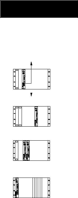
The following diagrams show three basic configurations for programming and debugging your ladder-logic programs.
PLC-5/VME processor
DH+ link
Connect a computer via the DH+ link, typically using a 1784-KT communication device in your IBM AT computer and a 1784-CP6 cable.
PLC-5/VME processor
RS-232
PC/CPU PLC-5/VME processor
19501
Connect a computer using the RS-232C on-board serial port of the PLC-5/VME processor. In this configuration, the RS-232C cable connects one of the computer's COM ports to the channel 0 (serial) port of the processor.
You can program as well as download files directly over the VMEbus backplane to your PLC-5/VME processor if you:
run 6200 Series PLC-5 Programming Software release 4.4 or later
use an 8086-based CPU from RadiSysÐi.e., a EPC-1, EPC-4, or EPC-5 VME PC-compatible computer.
Important: In order to use the save feature of the 6200 Series PLC-5 Programming Software when you communicate with the processor in this way, you must run release 4.5 or later.
1-5

Chapter 1
Overview
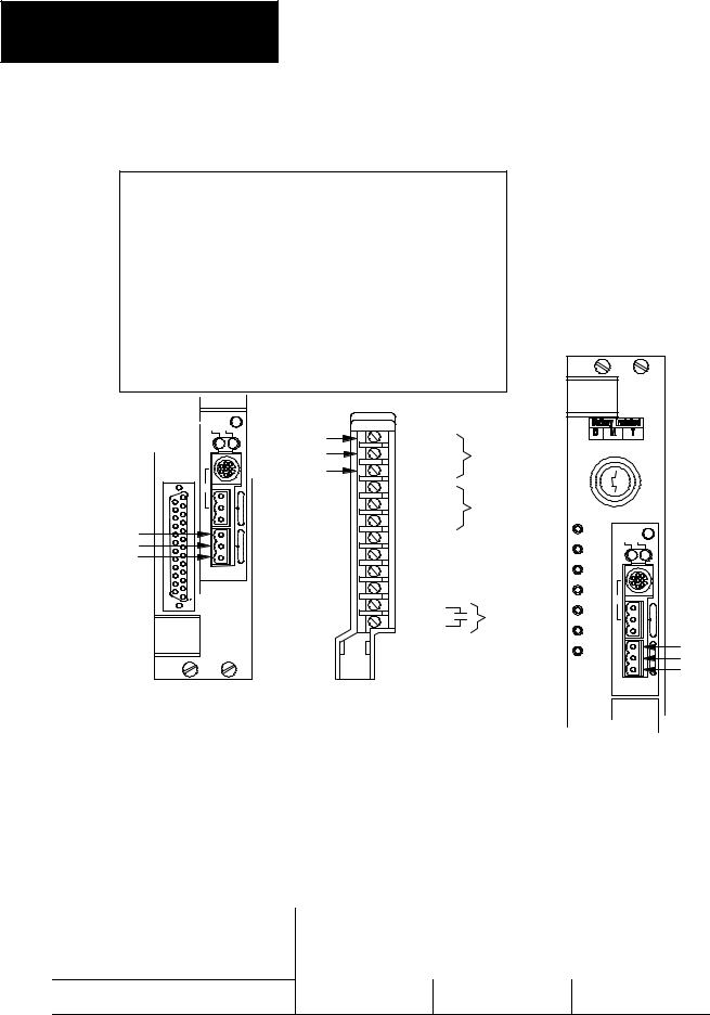
VMEbus Interface |
The PLC-5/VME is fully compliant with the C.1 VMEbus specification. |
|
The PLC-5/VME processor occupies two 6U VMEbus slots. It can reside |
|
in any adjacent pair of slots, including slot 1, the system-controller slot. |
|
The PLC-5/VME processor has a single VMEbus P1 connector, allowing it |
|
to be used in VMEbus systems that have either the full J1 and J2 |
|
backplanes or only the J1 backplane. |
|
The PLC-5/VME processor occupies 64 bytes in the VME A16 (or |
|
ªshortº) address space, and you can configure an additional 64 Kbytes of |
|
the A24 (or ªstandardº) address space. |
VMEbus
Configuration/control/
status/message registers in A16 space
Optional general-purpose memory in A24 space
The PLC-5/VME processor has 8 16-bit registers accessible in the VMEbus A16 address space. A set of switches establishes the base address of these registers. These registers can be used by a VMEbus CPU to establish certain programmable configuration options of the processor, control and monitor certain low-level conditions, and send commands to the processor.
The PLC-5/VME processor also has 64 KB of memory that can be enabled and mapped in the VME A24 address space. This memory is a general-purpose memory that you can use for any purpose (or not at all). If you enable it and tell the processor to do something to a VME address that happens to fall into this 64KB memory, the processor can access it without actually using VMEbus cycles. If you need some global VMEbus memory that can be accessed by the processor and another CPU, there may be performance benefits to using this 64KB of memory.
Processor
1-6
Chapter 1
Overview
Figure 1.2 illustrates the basic forms of communications. Table 1.A summarizes these communication forms.
|
|
Figure 1.2 |
|
||||
|
|
Basic Forms of Communications |
|
||||
|
|
|
|
|
1 |
|
Commands sent to the processor |
Ladder |
|
|
|
||||
|
|
|
|
|
|||
|
|
|
2 |
|
|||
|
|
|
|
|
|||
programs |
|
|
|
|
|
Read/write accesses to the processor's A16 registers and/or |
|
|
|
|
|
|
|||
|
|
|
|
|
3 |
|
the A24 memory block |
|
|
|
|
|
|
|
|
|
|
|
|
|
|
|
Interrupt to a ladder program |
|
|
|
|
|
4 |
|
|
|
|
|
|
|
|
Interrupt signalled by a ladder program |
|
|
|
|
|
|
|
|
|
|
|
|
|
|
5 |
|
|
|
|
|
|
|
|
One-shot block copy into or out of processor data files |
|
|
|
|
|
|
|
|
|
|
|
|
|
|
6 |
|
Continuous block copies into or out of processor data files |
|
|
|
|
|
|||
|
|
|
|
|
|
|
|
|
|
|
|
|
7 |
|
|
|
|
|
|
|
|
Interrupt signalling command completion |
|
|
|
|
|
|
|
|
|
|
|
|
|
|
8 |
|
|
|
|
|
|
|
|
|
Interrupt signalling completion of one block copy |
|
|
|
|
|
9 |
|
|
|
|
|
|
|
|
|
|
|
|
|
|
|
|
|
One-shot block copy into or out of processor data files as a |
Processor |
|
|
|
|
|
||
|
|
|
|
|
result of some commands sent to the processor |
||
data |
|
|
|
10 |
|
|
|
Files |
|
|
|
|
|
VMEbus SYSRESET |
|
|
|
|
11 |
|
|||
|
|
|
|
|
|
VMEbus SYSFAIL |
|
|
|
|
|
|
|
|
|
|
|
|
|
|
12 |
|
VMEbus ACFAIL 1 |
|
|
|
|
|
|
|
|
VME status file |
|
|
|
13 |
|
||
|
|
|
|
Optional VMEbus system controller functions |
|||
|
|
|
|
|
|||
|
|
|
|
|
|
|
|
|
|
|
|
|
1 Required by the PLC-5/VME processor. Asserted by VME power supply. |
||
|
|
|
|
|
|||
1-7

Chapter 1
Overview
|
Table 1.A |
|
Summary of Figure 1.2 |
|
|
In Figure 1.2, |
It means that: |
when you see : |
|
Commands are high-level directives sent to the processor from another VMEbus master, typically a controlling CPU. Commands specific to the VME processor can establish a continuous block copy to/from
1the processor and tell the processor to which VMEbus interrupts it should respond. You can also send any PCCC via this mechanism. PCCCs are commands supported in all 1785 PLC-5 processors. You can use them to change and modify processor state, for example, or to upload and download memory files.
2The PLC-5/VME processor responds as a VMEbus slave to certain A16 accesses (to its configuration registers) and to certain A24 accesses (to its general-purpose memory, if enabled).
You can configure the PLC-5/VME processor to respond as an interrupt handler to specified VMEbus
3interrupt lines. When one of these interrupts occurs, the processor performs an 8-bit interrupt acknowledge cycle on the VMEbus to read an 8-bit status/ID from the interrupter. The interrupt and the status/ID value are then posted for accessibility by the ladder program.
The PLC-5/VME processor can perform as a VMEbus interrupter (sender of interrupts) in three different ways:
•from a ladder program; the ladder MSG instruction has been extended in the PLC-5/VME processor to
4allow a ladder program to generate a VMEbus interrupt.
•signalling completion of a command (see 7).
•signalling a completion of each block copy operation for the continuous copy operations (see 8).
Another function available via the MSG instruction is VMEbus reads and writes. Rather than just individual
58- or 16-bit accesses, the function allows a block read or write to be done (i.e., of an arbitrary number of bytes). This is done between a data file in the processor and an arbitrary address range on the VMEbus. The ladder program can specify the VMEbus address space and data widths to be used.
One of the main interfaces of the 6008-LTV processor, and one preserved in the PLC-5/VME processor, is
6the ability to predefine two block-copy operations, one into the processor data files and one out of the processor data files, to be executed automatically every scan loop. These operations are predefined to the processor via initialization commands from the CPU or from your programming software.
7The processor can be a VMEbus interrupter signalling completion of a command. This is an option on all commands and can serve as a way to synchronize the CPU and the processor.
The processor can be a VMEbus interrupter signalling completion of each block copy operation for the
8continuous copy operations. This is another option that allows the CPU to synchronize with the scan loop of the processor.
9Certain standard PCCC commands cause data to be moved into and out of the processor; thus these commands represent another type of VMEbus interface between the processor and a controlling CPU.
The PLC-5/VME processor can be reset with the VME SYSRESET1 signal. The PLC-5/VME processor
10also asserts SYSRESET1 during power-up initialization until its VMEbus interface hardware is capable of responding to VMEbus accesses.
The PLC-5/VME processor asserts the VME SYSFAIL1 signal after a reset until the firmware's self-test
11completes successfully. The PLC-5/VME processor makes the state of the VME SYSFAIL1 signal available to the ladder program.
Assertion of VME ACFAIL1 causes the processor to halt, with integrity of the ladder program and data files
12maintained in the battery-backed memory such that the processor can be restarted upon power up. Your power supply must assert ACFAIL1 at least 9ms in advance of the +5VDC supply dropping beneath 4.75V.
The PLC-5/VME processor can serve as a VMEbus slot-1 system controller. This enables the PLC-5/VME
13processor as a single-level arbiter, a bus timeout timer, and the driver of the VMEbus 16 MHz SYSCLK signal.
1 indicates a low true signal.
1-8

Compatibility with the Standard PLC-5 Processor
Compatibility with the 6008-LTV Processor
Chapter 1
Overview
Ladder programs from a standard PLC-5 processor run in the PLC-5/VME processor. The PLC-5/VME processor has the same program scan time as the PLC-5 processor. The PLC-5/VME processor has the same extended instruction set as the PLC-5 processor.
Features of the PLC-5 processor not present in the PLC-5/VME processor are:
PIIs
EEPROM memory module logical rack 0 (128 less I/O points)
Features of the PLC-5/VME processor not present in the PLC-5 processor are:
The PLC-5/VME processor defines a special data file called the ªVME status file.º This file gives ladder programs the ability to control and monitor certain VMEbus state information.
The ladder MSG instruction is extended to allow ladder programs to perform VMEbus data transfers and generate VMEbus interrupts.
Finally, features present in both but implemented or represented differently are:
The serial port (channel 0) on the PLC-5/VME processor is RS-232C only (not configurable for RS-422 and RS-423).
Different batteries are used (cat. no. 1770-XYV).
The PLC-5/VME processor has a memory-protect switch. In the PLC-5 processor, the equivalent switch is on the 1771 I/O rack.
The PLC-5/VME processor retains a significant amount of compatibility with the 6008-LTV processor. This eases the task of converting 6008-LTV ladder programs and CPU driver programs to use with the PLC-5/VME processor.
6008-LTV ladder programs may need editing because the VME status file in the PLC-5/VME processor is different in several ways from 6008-LTV status file. The 6008-LTV ladder programs that access the VME status file will need to be changed.
1-9
Chapter 1
Overview
Table 1.B
Comparison of 6008-LTV and PLC-5/VME Processor Attributes
Attributes |
6008-LTV |
PLC-5/VME |
Comments |
|
|
|
|
VME slots |
3 |
2 |
|
|
|
|
|
Bus arbitration |
No |
Yes or No (user configurable) |
Single level arbiter |
|
|
|
|
VME master |
Yes |
Yes |
|
|
|
|
|
VME Slave |
Yes |
Yes |
|
|
|
|
|
Global memory (bytes)1 |
1K short, 4K short or standard |
64K standard |
Global memory is selectable |
Programming and downloading |
No |
Yes |
With 6200 series software |
over backplane |
|
|
release 4.4 and later |
|
|
|
|
Saving over backplane |
No |
Yes |
With 6200 series software |
|
|
|
release 4.5 and later |
|
|
|
|
PLC data table to global memory trans- |
Continuous-copy command |
Continuous-copy and/or ladder |
|
fer method |
|
MSG commands |
|
|
|
|
|
Asserts VME SYSFAIL |
Yes |
Yes |
|
|
|
|
|
PLC resets upon VME SYSRESET |
Yes |
Yes |
|
|
|
|
|
Bus request line |
0, 1, 2, 3 |
1, 3 |
|
|
|
|
|
Bus release |
ROR, RWD, ROC |
ROR, RWD, ROC |
|
|
|
|
|
Continuous-copy command file size |
500 words |
1000 words |
|
|
|
|
|
Ladder MSG file size |
N/A |
1000 words |
|
|
|
|
|
RS-232 port |
No |
Yes |
|
|
|
|
|
Remote I/O baud rate |
57.6k baud fixed |
57.6k, 115.2k, 230.4k baud configurable |
|
|
|
|
|
Remote I/O fractional rack addressing |
No |
Yes |
|
|
|
|
|
1 All of the 6008-LTV's global memory could be configured to be totally within short memory. Because the PLC-5/VME processor's global memory would totally fill all of
VME short memory, it can only be selected with a standard memory address. This may be a consideration when replacing a 6008-LTV with a PLC-5/VME processor.
There are some areas of potential incompatibility to consider:
The configuration/control/status/message registers are slightly different, requiring changes to the host driver program.
The LTV VME global memory can be selected to be in short or standard memory space. The PLC-5/VME processor's global memory can only be selected to be in standard memory. Because of this, the 6008-LTV will accept address modifiers 2D, 3D 29 and 39. The PLC-5/VME processor will only respond to address modifiers 3D.
The 6008-LTV supports logical rack address 0; the PLC-5/VME processor does not.
The 6008-LTV has a status/configuration bit to enable or ignore ROC (release on clear). The PLC-5/VME processor will always respond to ROC.
1-10

Chapter 1
Overview
The PLV-5/VME processor status files in the processor status area are different in several ways.
When floating point values are converted to integer, they are rounded differently. 6008-LTV rounds 0.5 to the next highest integer, the PLC-5/VME processor rounds to the nearest even integer.
CPU driver programs are affected in these ways:
The low-level protocol for how commands are given to the processor and how command-sending errors are reported is significantly different. However, the higher-level interfaces (e.g., the commands themselves) are compatible.
The manner in which the VME setup interface parameters are configured is significantly different:
In the: |
The information is in the: |
|
|
PLC-5/VME processor |
configuration registers in the A16 space. |
|
|
6008-LTV processor |
ªSlave 0º global memory in the A16 space. |
|
|
See chapter 3 for more information.
1-11

Chapter 2
Installation
Chapter Objectives
Compliance to
European Union Directives
Read this chapter to learn how to set the switches in your PLC-5/VME processor and install it into a VMEbus chassis.
See the Classic 1785 PLC-5 Programmable Controller Hardware Installation Manual, publication 1785-6.6.1 for more information about installing PLC-5 family processors.
If this product has the CE mark it is approved for installation within the European Union and EEA regions. It has been designed and tested to meet the following directives.
EMC Directive
This product is tested to meet Council Directive 89/336/EEC Electromagnetic Compatibility (EMC) and the following standards, in whole or in part, documented in a technical construction file:
•EN 50081-2EMC ± Generic Emission Standard, Part 2 ± Industrial Environment
•EN 50082-2EMC ± Generic Immunity Standard, Part 2 ± Industrial Environment
This product is intended for use in an industrial environment.
Low Voltage Directive
This product is tested to meet Council Directive 73/23/EEC Low Voltage, by applying the safety requirements of EN 61131±2 Programmable Controllers, Part 2 ± Equipment Requirements and Tests.
For specific information required by EN 61131-2, see the appropriate sections in this publication, as well as the following Allen-Bradley publications:
•Industrial Automation Wiring and Grounding Guidelines For Noise Immunity, publication 1770-4.1
•Enhanced and Ethernet PLC-5 Programmable Controller User Manual, publication 1785-6.5.12
•Guidelines for Handling Lithium Batteries, publication AG-5.4
•Automation Systems Catalog, publication B111
2-1
Chapter 2
Installation
Handling the Processor |
The processor is shipped in a static-shielded container to guard against |
|
electrostatic damage. Electrostatic discharge can damage integrated |
|
circuits or semiconductors in the processor module if you touch backplane |
|
connector pins. It can also damage the module when you set configuration |
|
plugs or switches inside the module. Avoid electrostatic damage by |
|
observing the following precautions. |
|
Remain in contact with an approved ground point while handling the |
|
module (by wearing a properly grounded wrist strap). |
|
Do not touch the backplane connector or connector pins. |
Wrist strap |
|
19897 |
When not in use, keep the module in its static-shielded container. |
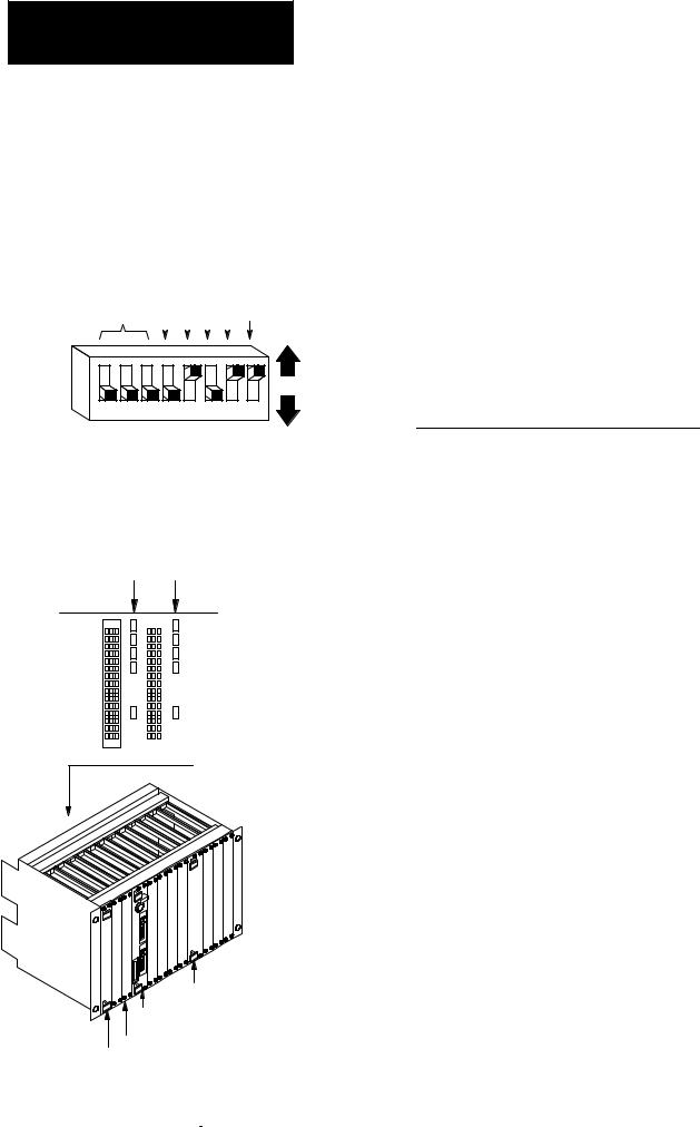
Setting the Switches |
Before installing the PLC-5/VME processor, you need to make some |
|
decisions about its configuration and operation and set the switches on the |
|
circuit board accordingly. You need to know: |
DH+ station (node) number
Memory protectionÐwhether you want the processor's program
RAM protected
Location of configuration registers in VMEbus A16 address space
System controllerÐwhether you want the processor to serve as the
VMEbus slot-1 system controller
VMEbus request levelÐwhether you want the processor to request access to the VMEbus at level 3 or level 1
Memory protect
DH+ station |
Power- |
||
up Test |
|||
number |
|||
|
|
|
|
|
|
|
|
|
|
|
|
Up |
|
|
|
|
|
|
|
|
(off) |
1 |
2 |
3 |
4 |
5 |
6 |
7 |
8 |
Down |
|
|
|
|
|
|
|
|
(on) |
SW1 set of switches
Figure 2.1
Switch Location
Front plate
SW1 |
SW2 |
Bottom |
19502 |
Table 2.A and Table 2.B describe the switch settings for SW1.
2-2

Chapter 2
Installation
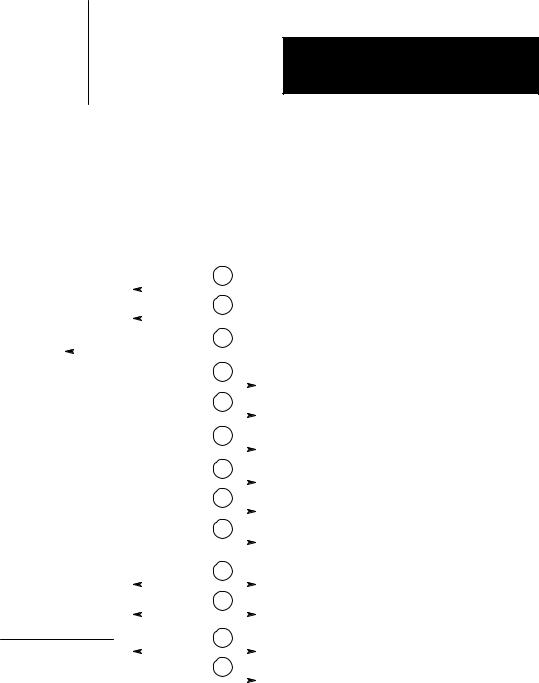
Table 2.A
SW1 Set of Switches
Switches 1-6 |
Switch 7 |
Switch 8 |
|
|
|
DH+ station number for channels |
Unused (off) |
Memory protect. |
1A and 0 (see Table 2.B) |
|
If on, RAM memory protect is enabled. |
|
|
|
Table 2.B
Station Numbers SW1 (Switches 1-6)
Station |
|
LSD |
|
|
MSD |
|
Number |
|
|
|
|
|
|
(Octal) |
1 |
2 |
3 |
4 |
5 |
6 |
|
|
|
|
|
|
|
0 |
on |
on |
on |
on |
on |
on |
|
|
|
|
|
|
|
1 |
off |
on |
on |
on |
on |
on |
|
|
|
|
|
|
|
2 |
on |
off |
on |
on |
on |
on |
|
|
|
|
|
|
|
3 |
off |
off |
on |
on |
on |
on |
|
|
|
|
|
|
|
. |
. |
. |
. |
. |
. |
. |
. |
. |
. |
. |
. |
. |
. |
. |
. |
. |
. |
. |
. |
. |
|
|
|
|
|
|
|
77 |
off |
off |
off |
off |
off |
off |
|
|
|
|
|
|
|
Table 2.C and Table 2.D describe the switch settings for SW2.
Table 2.C
SW2 Set of Switches
|
|
Switches 1-3 |
Switch 4 |
Switch 5 |
Switch 6 |
Switch 7 |
Switch 8 |
|
|
|
|
|
|
|
|
|
|
A16 address range of the |
If on, the processor functions as the VMEbus |
Unused |
VMEbus request level. |
Unused |
Unused |
|
|
configuration registers. |
system controller, and no other VME cards |
(off) |
If switch 4 is OFF, switch 6 on defines |
(off)1 |
(off) |
|
|
See Table 2.D. |
should attempt to be the system controller. |
|
the bus request level as 3. If switch 6 |
|
|
|
|
Important: The PLC-5/VME processor must |
|
|
|
||
|
|
|
|
is OFF, the bus request level is 1. |
|
|
|
|
|
|
be in the left-most slot of the VME chassis. |
|
If switch 4 is ON, the bus request |
|
|
|
|
|
See page 3-1 for a description of the |
|
|
|
|
|
|
|
|
level is 3 independent of the setting |
|
|
|
|
|
|
system controller. |
|
of switch 6. |
|
|
|
|
|
|
|
|
|
|
Important: Switch 6 is meaningful only if switch 4 is off.
1SW2, position 7, now controls whether the PLC-5 processor makes a VME self-reference in its POST test. If you set SW2, position 7 to OFF (up position), then the VME will make self-references as it did before series C, revision K. If you set SW2, position 7 to ON (down position), then the POST test will skip all VME self-references, causing the following effects:
±The PLC-5 processor cannot test its bus-master hardware.
±The PLC-5 processor cannot determine its own unique logical address and assumes its ULA is F0H regardless of how you set SW2, positions 1±3.
±The VME status file ULA field (word 1, bits 3-15) will always contain 000, regardless of how you set SW2, positions 1±3.
2-3
Chapter 2
Installation
System controller
|
Unused |
|||
|
(off) |
|||
|
|
Request |
||
|
|
|||
|
|
level |
||
|
|
|
Unused |
|
|
|
|
||
A16 |
|
|
(off) |
|
|
|
|
Unused |
|
address |
|
|
|
|
range |
|
|
|
(off) |
|
|
|
|
|
|
|
|
|
|
|
|
|
Up |
|
|
|
|
|
|
|
|
(off) |
1 |
2 |
3 |
4 |
5 |
6 |
7 |
8 |
Down |
|
SW2 set of switches |
|
|
(on) |
||||
|
|
|
|
|||||
Table 2.D
Address Range SW2 (Switches 1-3)
ULA 1 |
1 |
2 |
3 |
A16 Address Range |
0 |
on |
on |
on |
FC00-FC3F (hex) |
|
|
|
|
|
1 |
off |
on |
on |
FC40-FC7F |
|
|
|
|
|
2 |
on |
off |
on |
FC80-FCBF |
|
|
|
|
|
3 |
off |
off |
on |
FCC0-FCFF |
|
|
|
|
|
4 |
on |
on |
off |
FD00-FD3F |
|
|
|
|
|
5 |
off |
on |
off |
FD40-FD7F |
|
|
|
|
|
6 |
on |
off |
off |
FD80-FDBF |
|
|
|
|
|
7 |
off |
off |
off |
FDC0-FDFF |
|
|
|
|
|
1Unique Logical Address is used by the 6200 series programming software to determine the A16 base address of the PLC-5/VME processor's registers..
Configuring the VME
Backplane Jumpers
Five backplane jumpers
|
|
|
|
|
|
|
|
|
|
|
|
|
|
|
Left |
|
|
|
|
|
|
|
|
|
|
|
Right |
||
|
|
|
|
|
|
|
|
|
|
|
||||
|
|
|
|
|
|
|
|
|
|
|
||||
|
|
|
|
|
|
|
|
|
|
|
||||
|
|
|
|
|
|
|
|
|
|
|
||||
|
|
|
|
|
|
|
|
|
|
|
||||
|
|
|
|
|
|
|
|
|
|
|
||||
connector |
|
|
|
|
|
|
|
|
|
|
|
connector |
||
|
|
|
|
|
|
|
|
|
|
|||||
|
|
|
|
|
|
|
|
|
|
|
|
|
|
|
|
|
|
|
|
|
|
|
|
|
|
|
|
|
|
|
|
|
|
|
|
|
|
|
|
|
|
|
|
|
Backplane
The VMEbus contains several daisy-chained control signals. Almost all VMEbus backplanes contain jumpers for these control signals to allow systems to operate with empty slots. Failing to install these jumpers properly is a common source of problems in configuring a new VMEbus system.
There are five jumpers per VME slot, one for each of the four bus-grant arbitration levels and one for the interrupt-acknowledge daisy chain. Depending on the backplane manufacturer, the jumpers can be on the rear pins of the J1 connector or alongside it on the front of the backplane. The PLC-5/VME processor uses two slots. Based on what is in the VME slot, install or remove the backplane jumpers as follows:
VME Slot Content |
Five Backplane Jumpers |
|
|
PLC-5/VME processor's left slot |
Remove |
|
|
PLC-5/VME processor's right slot |
Install |
|
|
Empty slot |
Install |
|
|
Other VME module |
Consult manufacturer's literature |
|
|
Other VME module
PLC-5/VME processor
Note: Consult
manufacturer's Empty literature. CPU
2-4
Inserting the Processor into a Chassis
Chapter 2
Installation
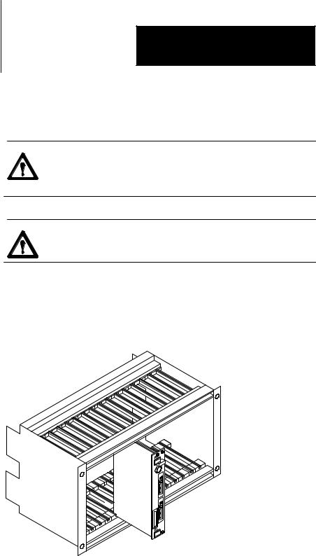
You insert the PLC-5/VME processor in two adjacent slots in a 6U (full-height) VMEbus chassis.
ATTENTION: Make sure that your VME system is powered off. The PLC-5/VME processor is not designed to be inserted or removed from a live system.
ATTENTION: Avoid touching the circuit board and connectors.
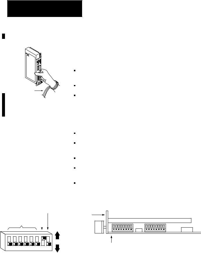
After sliding the processor into the VME chassis using its cardguides, use firm pressure on the top and bottom handles of the processor to make its P1 connector fit firmly into the connector on the backplane. Tighten the screws in the top and bottom of the front panel to prevent your PLC-5/VME processor from loosening.
|
19556 |
Grounding |
Allen-Bradley makes specific recommendations for properly grounding its |
|
racks so that their operation is as safe and error-free as possible. VME |
|
systems, on the other hand, may have no formal specifications for |
|
grounding the VME chassis frame. Allen-Bradley recommends that you |
|
ground the VME chassis frame and that you connect the logic ground |
|
(common) of the VME power supply to the chassis frame's earth ground. |
2-5

Chapter 2
Installation
Determining Power-Supply
Requirements
Connecting to Remote I/O
The specific procedure for grounding a VME chassis varies depending on the style of the chassis. Read the instructions found in the Classic PLC-5 Family Programmable Controllers Installation Manual, publication 1785-6.6.1 for information on how Allen-Bradley racks are grounded, and try to ground your VME chassis frame in a similar way.
ATTENTION: If you are using a PLC-5/V40L processor, your VME power supply should not float with respect to earth ground. Connect the power supply's logic ground (common) for the 5V supply before connecting the PLC-5/40L processor to a 1771-ALX adapter. Also, use a single point of ground between the VME chassis and the extended-local I/O system to ensure proper performance.
The PLC-5/VME processor draws 4 A (maximum)Ð3.2 A (typical)Ðfrom the VME power supply. The processor also monitors the ACFAIL signal on the backplane to determine when the +5 VDC supply is within tolerances. The VME power supply must assert ACFAIL at least 9 ms in advance of the +5 VDC supply dropping beneath 4.75V or memory corruption and processor fault occurs. Therefore, make sure that your power supply has ACFAIL capability.
You must use a Safety Extra Low Voltage (SELV)- or Protected Extra Low Voltage (PELV)-certified power supply with the VME processor to comply with Low Voltage directive requirements.
Use Belden 9463 twin-axial cable (cat. no.1770-CD) to connect devices to a remote I/O link. To connect a remote I/O link, do the following:
To connect a remote I/O link, you must: |
See page: |
|
|
Make sure the cables are the correct length |
2-6 |
|
|
Prepare the cable |
2-7 |
|
|
Make the remote I/O connections |
2-7 |
|
|
Terminate the link |
2-8 |
|
|
Make Sure that You Have Correct Cable Lengths
Verify that your system's design plans specify remote I/O cable lengths within allowable measurements.
2-6

Chapter 2
Installation
A remote I/O link using this communication rate: |
Cannot exceed this cable length: |
|
|
57.6 kbps |
3,048 m (10,000 ft) |
|
|
115.2 kbps |
1,524 m (5,000 ft) |
|
|
230.4 kbps |
762 m (2,500 ft) |
|
|
Prepare the Cable
Cut the cable according to the lengths you need. Route the cable to the devices.
Make Remote I/O Connections
Use Figure 2.2 when connecting the remote I/O cable to PLC-5 processors and remote I/O adapter modules.
2-7
Chapter 2
Installation
|
Figure 2.2 |
|
|
|
|
|
|
Remote I/O Terminal Connectors |
|
|
|
||
To connect remote I/O cable, do the following: |
|
|
|
|
||
1. Run the cable (1770-CD) from the processor to each remote I/O |
|
|
|
|||
adapter module or processor in the remote I/O system. |
|
|
|
|
||
2. Connect the signal conductor with blue insulation to the 3-pin |
|
|
|
|||
connector terminal labeled 1 on the processor and to each remote |
|
|
|
|||
I/O adapter module (or PLC-5 adapter) in the remote I/O system. |
|
|
|
|||
3. Connect the signal conductor with clear insulation to the 3-pin |
|
|
|
|||
connector terminal labeled 2. |
|
|
|
|
|
|
4. Connect the shield drain wire to the 3-pin terminal labeled SH. |
|
|
|
|||
5. Tie wrap the remote I/O network cable to the chassis to relieve strain |
|
|
||||
on the cable. |
|
|
|
|
|
|
|
Blue |
1 |
Line 1 |
|
|
|
|
Shield |
2 |
Shield |
Cable |
|
|
Chan 0 |
Clear |
3 Line 2 |
|
|
|
|
|
|
4 |
Line 1 |
Cable for |
|
|
|
|
5 |
Shield |
daisy-chain |
Chan 1 |
|
Blue |
|
6 |
Line 2 |
configuration |
|
|
|
|
|
|
|||
|
7 No Connection |
|
|
|||
Shield |
|
|
|
|||
Remote I/O |
8 No Connection |
|
|
|||
Clear |
|
|
||||
Terminal |
9 |
No Connection |
|
|
||
|
|
|
||||
Chan 2 |
Connectors |
10 No Connection |
|
|
||
|
|
|
||||
|
11 |
In |
|
|
|
|
|
|
Reset |
|
|
||
|
|
12 Ret |
|
|
||
|
|
|
|
|
||
|
|
|
|
|
|
Blue |
|
|
|
|
Remote I/O |
|
Shield |
|
|
|
|
|
Clear |
|
|
|
|
|
Terminal |
|
|
|
|
|
|
|
|
|
PLC-5/V40B |
|
1771-ASB Remote |
Connectors |
|
|
|
|
|
I/O Adapter Module |
|
|
|
|
Processor channel must be configured for remote I/O communication. |
|
PLC-5/V40L |
19539 |
|||
|
|
|||||
Terminate the Link
For proper operation, terminate both ends of a remote I/O link by using the external resistors shipped with the programmable controller. Use either a 150W or 82W terminator.
If your remote I/O link: |
Use this resistor rating: |
The maximum number of |
The maximum number of |
|
|
physical devices you |
racks you can scan on |
|
|
can connect on the link |
the link |
|
|
|
|
operates at 230.4 kbps |
82W |
32 |
16 |
|
|
|
|
operates at 57.6 kbps or 115.2 kbps and no devices listed in Table 2.A are on the link
2-8
Loading...