


2080-LC50
Table of contents
 Loading...
Quick Start
Micro800 Programmable Controllers: Getting Started with
Motion Control Using a Simulated Axis
Catalog Numbers Bulletin 2080-LC30, 2080-LC50
Important User Information
IMPORTANT
Solid-state equipment has operational characteristics differing from those of electromechanical equipment. Safety
Guidelines for the Application, Installation and Maintenance of Solid State Controls (publication SGI-1.1
your local Rockwell Automation sales office or online at http://www.rockwellautomation.com/literature/
important differences between solid-state equipment and hard-wired electromechanical devices. Because of this difference,
and also because of the wide variety of uses for solid-state equipment, all persons responsible for applying this equipment
must satisfy themselves that each intended application of this equipment is acceptable.
In no event will Rockwell Automation, Inc. be responsible or liable for indirect or consequential damages resulting from the
use or application of this equipment.
The examples and diagrams in this manual are included solely for illustrative purposes. Because of the many variables and
requirements associated with any particular installation, Rockwell Automation, Inc. cannot assume responsibility or
liability for actual use based on the examples and diagrams.
No patent liability is assumed by Rockwell Automation, Inc. with respect to use of information, circuits, equipment, or
software described in this manual.
Reproduction of the contents of this manual, in whole or in part, without written permission of Rockwell Automation,
Inc., is prohibited.
Throughout this manual, when necessary, we use notes to make you aware of safety considerations.
available from
) describes some
WARNING: Identifies information about practices or circumstances that can cause an explosion in a hazardous environment,
which may lead to personal injury or death, property damage, or economic loss.
ATTENTION: Identifies information about practices or circumstances that can lead to personal injury or death, property
damage, or economic loss. Attentions help you identify a hazard, avoid a hazard, and recognize the consequence.
SHOCK HAZARD: Labels may be on or inside the equipment, for example, a drive or motor, to alert people that dangerous
voltage may be present.
BURN HAZARD: Labels may be on or inside the equipment, for example, a drive or motor, to alert people that surfaces may
reach dangerous temperatures.
Identifies information that is critical for successful application and understanding of the product.
Allen-Bradley, Micro800, Micro830, Micro850, Connected Components Workbench, PanelView, Rockwell Software, Rockwell Automation, and TechConnect are trademarks of Rockwell Automation, Inc.
Trademarks not belonging to Rockwell Automation are property of their respective companies.

Preface
About This Publication
This quick start is designed to provide instructions for implementing a motion
control project using Connected Components Workbench™ software and a
Micro830™/Micro850™ programmable logic controller (PLC). It makes use
of a sample project to illustrate the basic steps that a user needs to perform to
use the motion control feature in Micro830 and Micro850 controllers.
To assist in the design and installation of your system, refer to the Micro830
and Micro850 Programmable Controllers User Manual, publication
2080-UM002
The beginning of each chapter contains the following information. Read these
sections carefully before beginning work in each chapter.
• Before You Begin – This section lists the steps that must be completed
• What You Need – This section lists the tools that are required to
• Follow These Steps – This illustrates the steps in the current chapter
.
and decisions that must be made before starting that chapter. The
chapters in this quick start do not have to be completed in the order in
which they appear, but this section defines the minimum amount of
preparation required before completing the current chapter.
complete the steps in the current chapter. This includes, but is not
limited to, hardware and software.
and identifies which steps are required to complete the examples using
specific networks.
Audience
Required Software
To be able to use the motion control feature effectively, you need to be familiar
with programming in function block diagram, structured text, and ladder
programming.
This quick start works hand-in-hand with Micro830 and Micro850
Programmable Controllers User Manual, publication 2080-UM002
To complete this quick start, the following software is required:
• Connected Components Workbench revision 2 and later
Connected Components Workbench is the main programming software
for Micro800 systems. It provides a choice of IEC 61131-3
programming languages (ladder diagram, function block diagram,
structured text) with user defined function block support that optimizes
machine control.
You will need the Connected Components Workbench software to
configure your axis parameters, write your motion control function
block programs, execute your function blocks, and monitor your axis
status.
.
iiiPublication 2080-QS001A-EN-E - January 2013 iii
Preface
Additional Resources
Resource Description
Micro830 and Micro850 User Manual, publication
2080-UM002
Micro800 Programmable Controller External AC Power
Supply Installation Instructions, publication 2080-IN001
A detailed description of how to install and use your Micro830 and Micro850
programmable controller and expansion I/O system.
Information on wiring and installing the optional AC power supply.
Kinetix 3 Motion Control Indexing Application,
publication CC-QS025
Industrial Automation Wiring and Grounding Guidelines,
publication 1770-4.1
Connected Components Workbench Online Help Online Help that provides a description of the different elements of the
Quick start instructions designed to provide instructions for implementing a
Kinetix® 3 component-class drive motion control indexing application by using
Connected Components Workbench software and a Micro830 programmable
logic controller (PLC).
More information on proper wiring and grounding techniques.
Connected Components Workbench software.
iv Publication 2080-QS001A-EN-E - January 2013

Create a Micro800 Project
Table of Contents
Important User Information . . . . . . . . . . . . . . . . . . . . . . . . . . . . . . . . . . . . . . . . ii
Preface
About This Publication . . . . . . . . . . . . . . . . . . . . . . . . . . . . . . . . . . . . . . . . . . . iii
Audience . . . . . . . . . . . . . . . . . . . . . . . . . . . . . . . . . . . . . . . . . . . . . . . . . . . . . . . . . iii
Required Software. . . . . . . . . . . . . . . . . . . . . . . . . . . . . . . . . . . . . . . . . . . . . . . . . iii
Additional Resources . . . . . . . . . . . . . . . . . . . . . . . . . . . . . . . . . . . . . . . . . . . . . . iv
Where to Start
Overview of Sample Project . . . . . . . . . . . . . . . . . . . . . . . . . . . . . . . . . . . . . . . .vii
Optional: PanelView Component . . . . . . . . . . . . . . . . . . . . . . . . . . . . . . . . . .vii
Hardware and Software Compatibility . . . . . . . . . . . . . . . . . . . . . . . . . . . . . viii
Follow These Steps . . . . . . . . . . . . . . . . . . . . . . . . . . . . . . . . . . . . . . . . . . . . . . . . ix
Chapter 1
Introduction . . . . . . . . . . . . . . . . . . . . . . . . . . . . . . . . . . . . . . . . . . . . . . . . . . . . . .1
Before You Begin . . . . . . . . . . . . . . . . . . . . . . . . . . . . . . . . . . . . . . . . . . . . . . . . . . 1
What You Need . . . . . . . . . . . . . . . . . . . . . . . . . . . . . . . . . . . . . . . . . . . . . . . . . . . 1
Create a Micro800 Project in Connected Components Workbench . . . . 2
Configure Motion Axis Properties
Write Your Motion Control Programs
Chapter 2
Introduction . . . . . . . . . . . . . . . . . . . . . . . . . . . . . . . . . . . . . . . . . . . . . . . . . . . . . .5
Before You Begin . . . . . . . . . . . . . . . . . . . . . . . . . . . . . . . . . . . . . . . . . . . . . . . . . . 5
What You Need . . . . . . . . . . . . . . . . . . . . . . . . . . . . . . . . . . . . . . . . . . . . . . . . . . . 5
Follow These Steps . . . . . . . . . . . . . . . . . . . . . . . . . . . . . . . . . . . . . . . . . . . . . . . . . 6
Configure General Properties . . . . . . . . . . . . . . . . . . . . . . . . . . . . . . . . . . . . . . .7
Configure Motor and Load Properties . . . . . . . . . . . . . . . . . . . . . . . . . . . . . . .9
Configure Limits Properties . . . . . . . . . . . . . . . . . . . . . . . . . . . . . . . . . . . . . . .10
Configure Dynamics Properties . . . . . . . . . . . . . . . . . . . . . . . . . . . . . . . . . . . .11
Configure Homing Properties . . . . . . . . . . . . . . . . . . . . . . . . . . . . . . . . . . . . .12
Configure Embedded I/O Properties . . . . . . . . . . . . . . . . . . . . . . . . . . . . . . .13
Chapter 3
Introduction . . . . . . . . . . . . . . . . . . . . . . . . . . . . . . . . . . . . . . . . . . . . . . . . . . . . .15
Before You Begin . . . . . . . . . . . . . . . . . . . . . . . . . . . . . . . . . . . . . . . . . . . . . . . . .15
What You Need . . . . . . . . . . . . . . . . . . . . . . . . . . . . . . . . . . . . . . . . . . . . . . . . . .15
Follow These Steps . . . . . . . . . . . . . . . . . . . . . . . . . . . . . . . . . . . . . . . . . . . . . . . .16
Create Axis_PowerUp Program . . . . . . . . . . . . . . . . . . . . . . . . . . . . . . . . . . . .17
Create Homing Program . . . . . . . . . . . . . . . . . . . . . . . . . . . . . . . . . . . . . . . . . .21
Create Program for MC_MoveRelative . . . . . . . . . . . . . . . . . . . . . . . . . . . . .28
Create Program for MC_MoveAbsolute Function Block . . . . . . . . . . . . .31
Create Program for MC_MoveVelocity Function Block . . . . . . . . . . . . .36
Create Program for MC_TouchProbe Function Block . . . . . . . . . . . . . . .43
Build and Download Programs . . . . . . . . . . . . . . . . . . . . . . . . . . . . . . . . . . . . .48
v Publication 2080-QS001A-EN-E - January 2013

vi Table of Contents
Wire Your Controller for Motion Control
Execute Your Motion Control Function Blocks
Chapter 4
Introduction . . . . . . . . . . . . . . . . . . . . . . . . . . . . . . . . . . . . . . . . . . . . . . . . . . . . .49
What You Need . . . . . . . . . . . . . . . . . . . . . . . . . . . . . . . . . . . . . . . . . . . . . . . . . .49
Wire the Controller . . . . . . . . . . . . . . . . . . . . . . . . . . . . . . . . . . . . . . . . . . . . . . .50
Chapter 5
Introduction . . . . . . . . . . . . . . . . . . . . . . . . . . . . . . . . . . . . . . . . . . . . . . . . . . . . .51
Before You Begin . . . . . . . . . . . . . . . . . . . . . . . . . . . . . . . . . . . . . . . . . . . . . . . . .51
What You Need . . . . . . . . . . . . . . . . . . . . . . . . . . . . . . . . . . . . . . . . . . . . . . . . . .51
Follow These Steps . . . . . . . . . . . . . . . . . . . . . . . . . . . . . . . . . . . . . . . . . . . . . . . .52
Go to Remote RUN Mode . . . . . . . . . . . . . . . . . . . . . . . . . . . . . . . . . . . . . . . .52
Axis Monitoring . . . . . . . . . . . . . . . . . . . . . . . . . . . . . . . . . . . . . . . . . . . . . . . . . .53
Power Up the Motion Axis . . . . . . . . . . . . . . . . . . . . . . . . . . . . . . . . . . . . . . . .54
Execute MC_Home . . . . . . . . . . . . . . . . . . . . . . . . . . . . . . . . . . . . . . . . . . . . . . .55
Execute MC_MoveRelative . . . . . . . . . . . . . . . . . . . . . . . . . . . . . . . . . . . . . . . .58
Execute MC_MoveAbsolute . . . . . . . . . . . . . . . . . . . . . . . . . . . . . . . . . . . . . . .61
Execute MC_MoveVelocity and MC_Halt . . . . . . . . . . . . . . . . . . . . . . . . .66
Execute MC_TouchProbe . . . . . . . . . . . . . . . . . . . . . . . . . . . . . . . . . . . . . . . . .69
Implementing Motion Control in an Actual Environment . . . . . . . . . . .70
Publication 2080-QS001A-EN-E - January 2013

Where to Start
Micro850
controller
Simulated Linear Actuator
Home
Sensor
Direction
output
Pulse Train
Output
Upper
Limit
moving
object
PanelView
Component
Lower
Limit
optional component
TIP
HSC wiring for PTO feedback is not shown and is for simulation purposes only.
Overview of Sample Project
This quick start instruction serves to enable users to the use the motion control feature on Micro830 and Micro850
controllers. It uses a sample simulation program to familiarize the user with motion control instructions and related
parameter and wiring configurations. In particular, this project lets the user enable an axis, home an axis, move an axis, and
use touch probe to capture current position in a simulated environment.
The project uses the minimum components to use motion control. It does not require a servo drive. The PTO output is
wired directly to the high speed counter input. It makes use of high speed counter inputs to count the pulse train output
(PTO) for the current position.
The following diagram illustrates how this project simulates motion control. The elements of this project are shown in the
following diagram.
Download the Simulation Project
You can also download the code for the complete simulation project from the following link:
http://www.rockwellautomation.com/go/scmicro800
The downloadable code includes an optional PanelView Component (PVc) program, which allows the user to easily update
and monitor different axis parameters through a PVc screen.
If you opt not to use a PanelView Component, use the Connected Components Workbench software to toggle variable
input values and trigger motion instructions. Axis monitoring can also be done through the same software through the Axis
Monitor feature.
To get started, check that your Micro800 controller supports motion control.
viiPublication 2080-QS001A-EN-E - January 2013 vii
Where to Start
IMPORTANT
Hardware and Software Compatibility
The motion control feature on Micro830 and Micro850 controller is implemented through Pulse Train Outputs (PTOs)
and motion axes, which are summarized in the following table.
PTO and Motion Axis Support on Micro830 and Micro850 Controllers
Controller PTO (built-in) Number of Axes Supported
10/16 Points
2080-LC30-10QVB
2080-LC30-16QVB
24 Points
2080-LC30-24QVB
2080-LC30-24QBB
2080-LC50-24QVB
2080-LC50-24QBB
48 Points
2080-LC30-48QVB
2080-LC30-48QBB
2080-LC50-48QVB
2080-LC50-48QBB
Software and Firmware Requirements
• For programming, motion control is supported on Connected Components Workbench software
revision 2 and later.
• Micro830 controllers require firmware revision 2 and later.
11
22
33
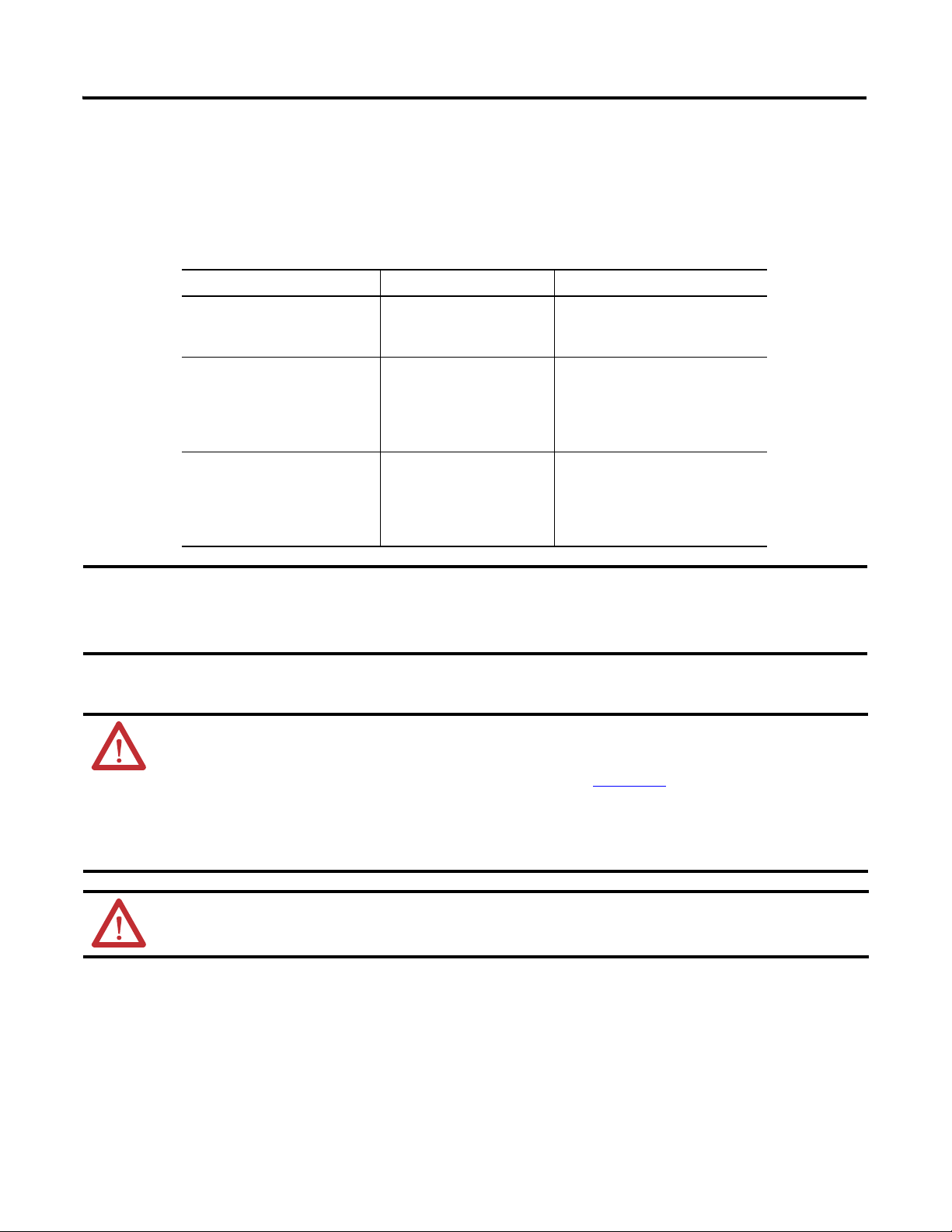
ATTENTION: To use the Micro800 motion control feature effectively, users need to have a basic
understanding of the following:
• PTO components and parameters
See the Micro830 and Micro850 User Manual, publication 2080-UM002
components and their relationships.
• Programming and working with elements in the Connected Components Workbench software
The user needs to have a working knowledge of ladder diagram, structured text, or function block diagram
programming to be able to work with motion function blocks, variables, and axis configuration parameters.
, for a general overview of Motion
ATTENTION: To learn more about Connected Components Workbench and detailed descriptions of the
variables for the Motion Function Blocks, you can refer to Connected Components Workbench Online Help that
comes with your Connected Components Workbench installation.
viii Publication 2080-QS001A-EN-E - January 2013
Where to Start
Upper
Right
Limit
Lower
Left
Limit
Home
Sensor
The axis moves 200 mm relative to the current position.
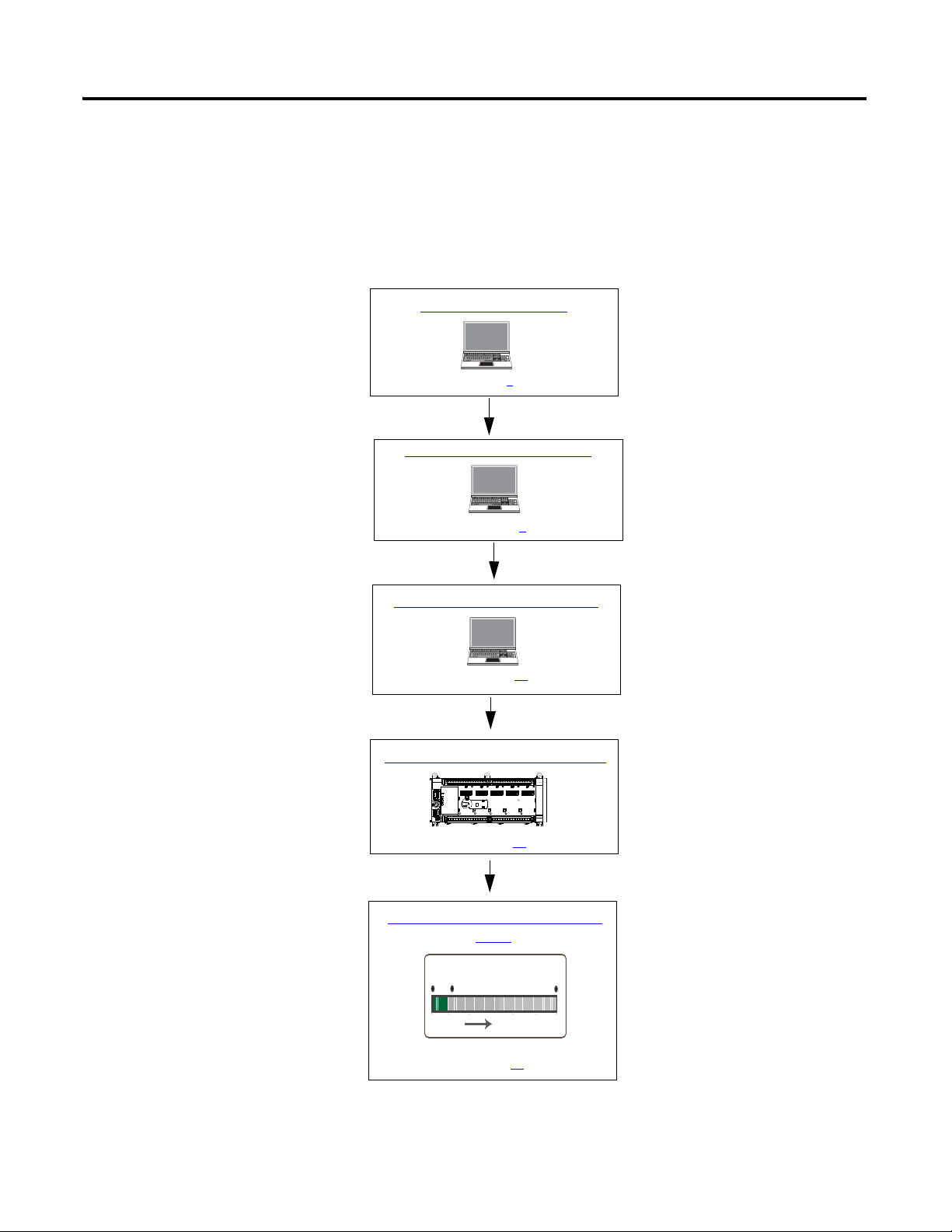
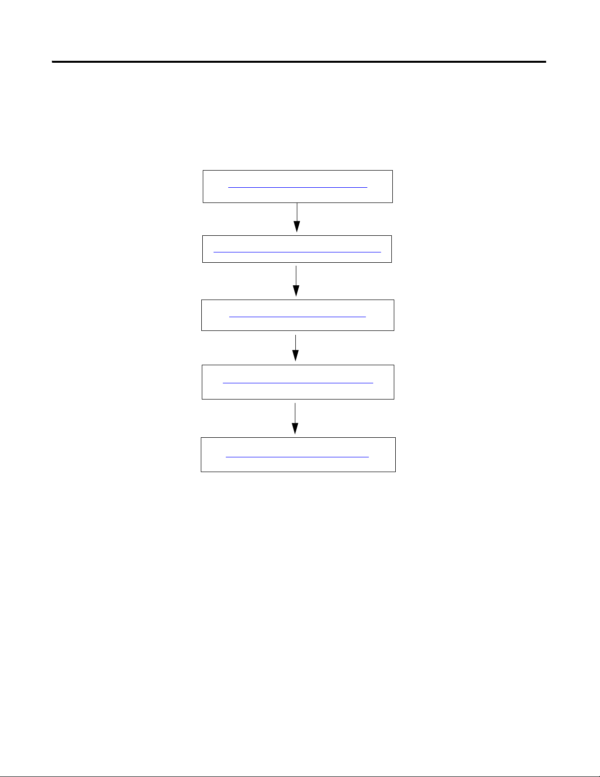
Configure Motion Axis Properties
Write Your Motion Control Programs
Create a Micro800 Project
Wire Your Controller for Motion Control
See page 1
See page 5
See page 15
See page 49
Execute Your Motion Control Function
Blocks
See page 51
Follow These Steps
The major subsections for this quick start project are outlined in the following flowchart. Follow the steps under each
subsection to become familiar with the required procedure to configure your controller and set up a simulation project for
motion control.
Publication 2080-QS001A-EN-E - January 2013 ix

Where to Start
Notes:
x Publication 2080-QS001A-EN-E - January 2013

Chapter
Create a Micro800 Project
Introduction
In this chapter, you will create a sample Micro830/Micro850 controller project through the Connected Components
Wor kb en ch .
Before You Begin
Ensure that you have Connected Components Workbench revision 2 properly installed.
1
What You Need
• Connected Components Workbench revision 2 or later
• Firmware revision 2 and later for Micro830 controllers
1Publication 2080-QS001A-EN-E - January 2013 1
Chapter 1 Create a Micro800 Project
TIP
IMPORTANT
IMPORTANT
Create a Micro800 Project in Connected Components Workbench
Launch the Connected Components Workbench software.
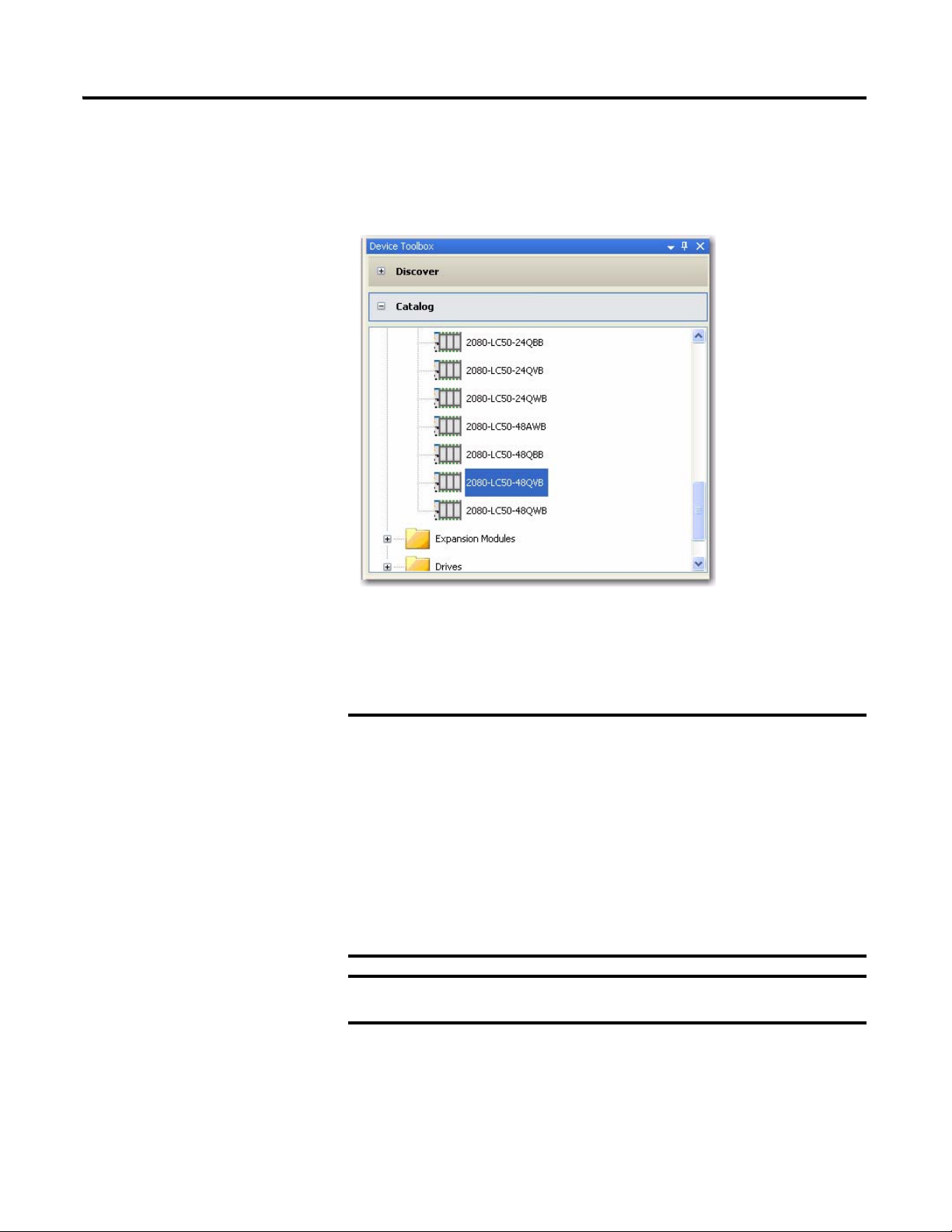
1. On the Device Toolbox, expand the list of Controllers by clicking the + sign.
If your controller is online, use the Discover feature to
automatically discover your controller.
Make sure that your controller is one of the following
compatible controllers:
• 2080-LC30-24QBB
• 2080-LC30-24QVB
• 2080-LC30-48QBB
• 2080-LC30-48QVB
• 2080-LC50-24QBB
• 2080-LC50-24QVB
• 2080-LC50-48QBB
• 2080-LC50-48QVB
Motion control on Micro830 controllers require firmware revision 2
or later.
2 Publication 2080-QS001A-EN-E - January 2013
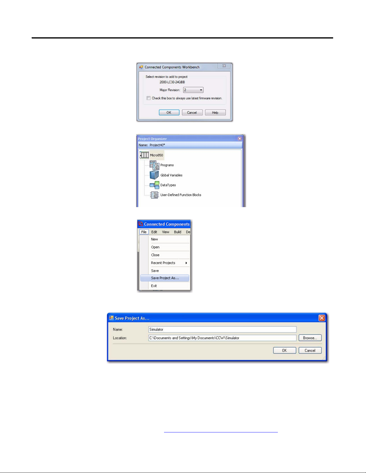
2. Select major revision 2 when
TIP
manually adding a Micro830
controller.
3. Drag your controller onto the Project Organizer pane.
Create a Micro800 Project Chapter 1
4. Go to File → Save Project As.
Then, provide a project name for
your project.
5. Click OK.
Optional PanelView Component Program
This simulation project can also include a PanelView Component program to
allow for easier monitoring and toggling of axis parameter values through a
PVc screen. The code for this optional program is downloadable from the
following link, along with the complete code for this project:
http://www.rockwellautomation.com/go/scmicro800
Publication 2080-QS001A-EN-E - January 2013 3

Chapter 1 Create a Micro800 Project
Notes:
4 Publication 2080-QS001A-EN-E - January 2013

Configure Motion Axis Properties
Introduction
In this chapter, you will configure the axis parameters through Connected Components Workbench.
Topic Page
Configure General Properties 7
Configure Motor and Load Properties 9
Configure Limits Properties 10
Configure Dynamics Properties 11
Configure Homing Properties 12
Chapter
2
Before You Begin
Acquire a basic understanding of the different motion axis parameters by referring to the Micro830 and Micro850
Programmable Controllers User Manual, publication 2080-UM002
Online Help.
and/or the Connected Components Workbench
What You Need
• Connected Components Workbench revision 2 or later
• Firmware revision 2 and later for Micro830 controllers
5Publication 2080-QS001A-EN-E - January 2013 5
Chapter 2 Configure Motion Axis Properties
Configure General Properties on page 7
Configure Motor and Load Properties on page 9
Configure Limits Properties on page 10
Configure Dynamics Properties on page 11
Configure Homing Properties on page 12
Follow These Steps
To configure your axis, follow these steps.
6 Publication 2080-QS001A-EN-E - January 2013

Configure General Properties
Launch the Connected Components Workbench software.
Configure Motion Axis Properties Chapter 2
1. Open the project you have created in the previous chapter.
2. On the Project Organizer pane, double-click the controller name to bring up the Device Properties pane.
3. Under the Controller properties tree, go to Motion. Right-click <New Axis> and choose Create.
4. Provide the name "Simulator" for the axis. Alternatively, you can press F2 to name the axis.
Publication 2080-QS001A-EN-E - January 2013 7
Chapter 2 Configure Motion Axis Properties
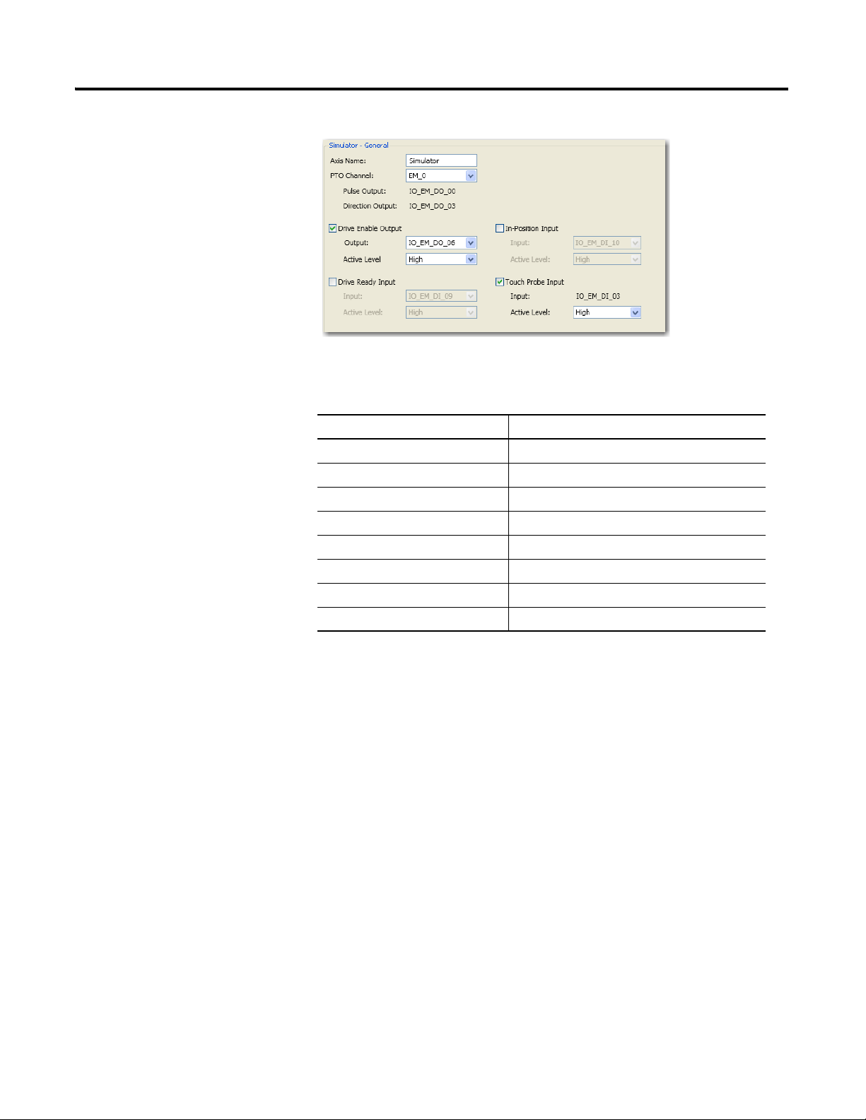
5. Click General to bring up the General properties tab.
6. Configure the general properties as shown in the table.
General Properties Parameters
Parameter Value
Axis Name Simulator
PTO Channel EM_0
Enable Drive Enable Output Tick option box to enable
Drive Enable Output IO_EM_DO_06
Drive Enable Output Active Level High
Enable Touch Probe Input Tick option box to enable
Touch Probe Input IO_EM_DI_03
Touch Probe Input Active Level High
8 Publication 2080-QS001A-EN-E - January 2013
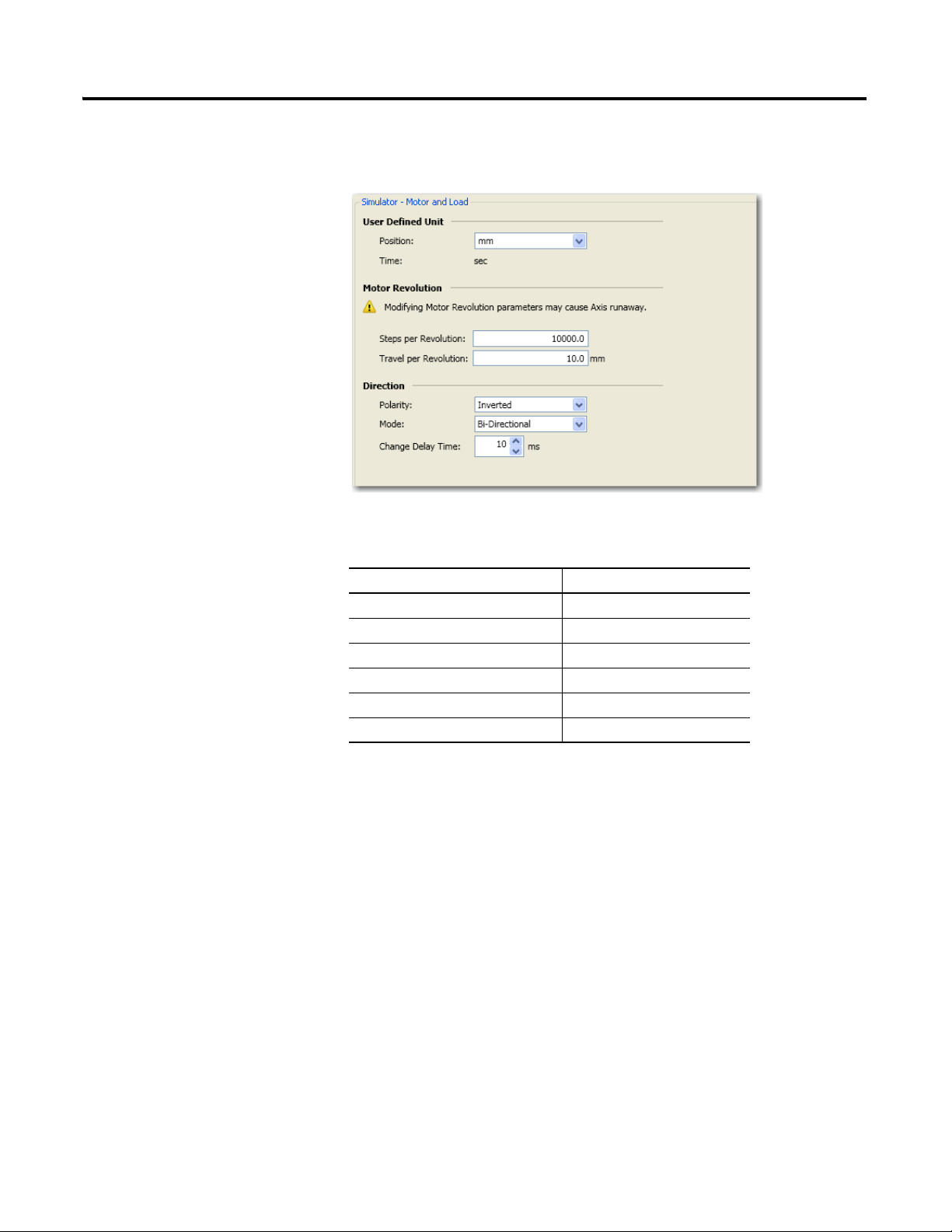
Configure Motor and Load Properties
1. On the Controller Configuration tree, under Motion, click Motor and Load to bring up the Motor and Load tab.
Configure Motion Axis Properties Chapter 2
2. Configure Motor and Load parameters as follows.
Motor and Load Properties
Parameter Value
Position mm
Steps per revolution 10000
Travel per revolution 10 mm
Polarity Inverted
Mode Bi-directional
Change delay time 10 ms
Publication 2080-QS001A-EN-E - January 2013 9

Chapter 2 Configure Motion Axis Properties
Configure Limits Properties
1. On the Controller Configuration tree, under Motion, click Limits to bring up the Limits properties tab.
2. Configure Limits parameters as shown in the table.
Limits Properties
Parameter Value
When hard limits is reached, apply Emergency Stop Profile
Lower Hard Limit Tick option box to enable
Lower Hard Limit Active Level High
Upper Hard Limit Tick option box to enable
Upper Hard Limit Active Level High
10 Publication 2080-QS001A-EN-E - January 2013
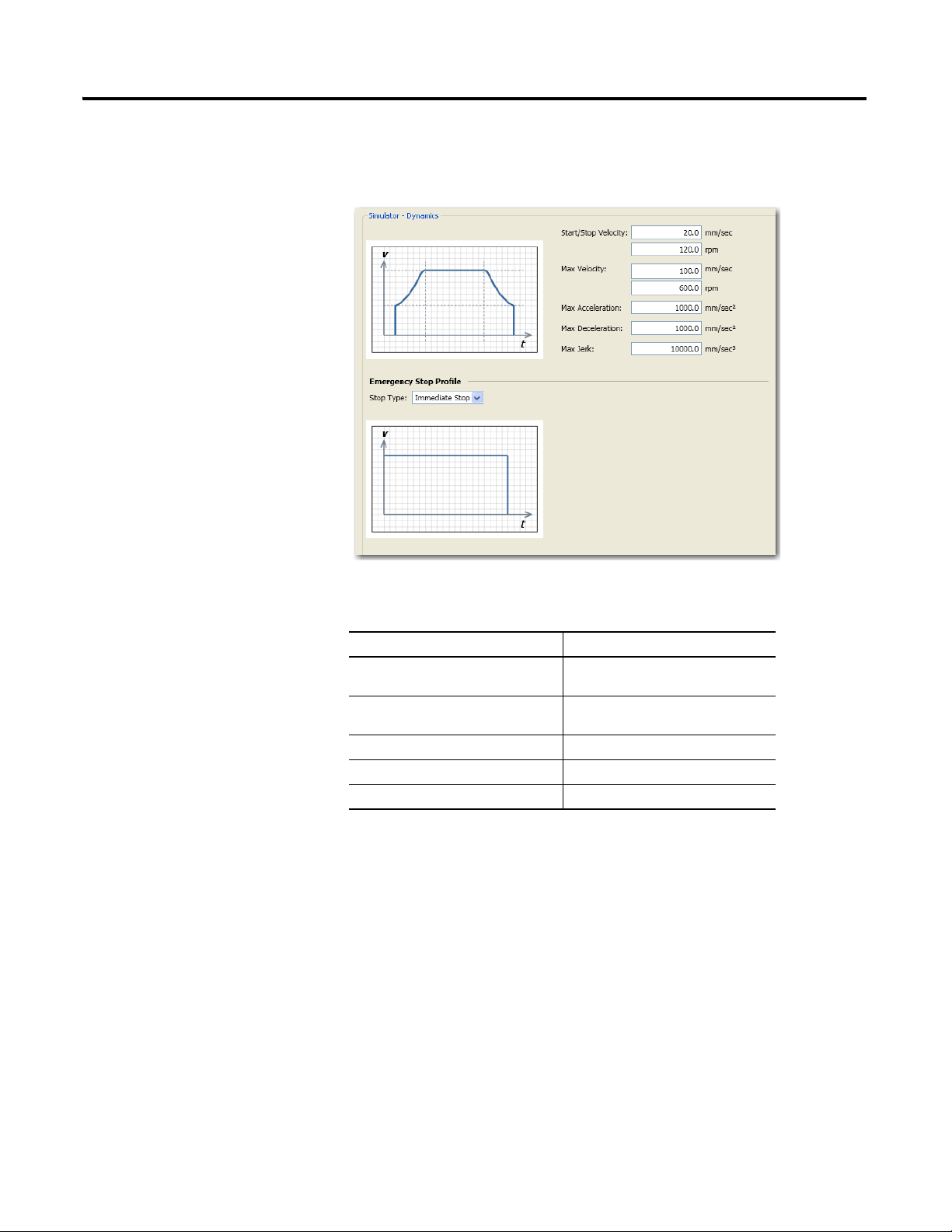
Configure Dynamics Properties
1. Under Motion, click Dynamics to bring up the Dynamics properties tab.
Configure Motion Axis Properties Chapter 2
2. Configure Dynamics parameters as shown in the table.
Dynamics Properties
Parameter Value
Start/Stop Velocity 20.0 mm/sec
120.0 rpm
Max Velocity 100.0 mm/sec
600.0 rpm
Max Acceleration 1000 mm/sec
Max Deceleration 1000 mm/sec
Max Jerk 10000 mm/sec
2
2
3
Publication 2080-QS001A-EN-E - January 2013 11
Chapter 2 Configure Motion Axis Properties
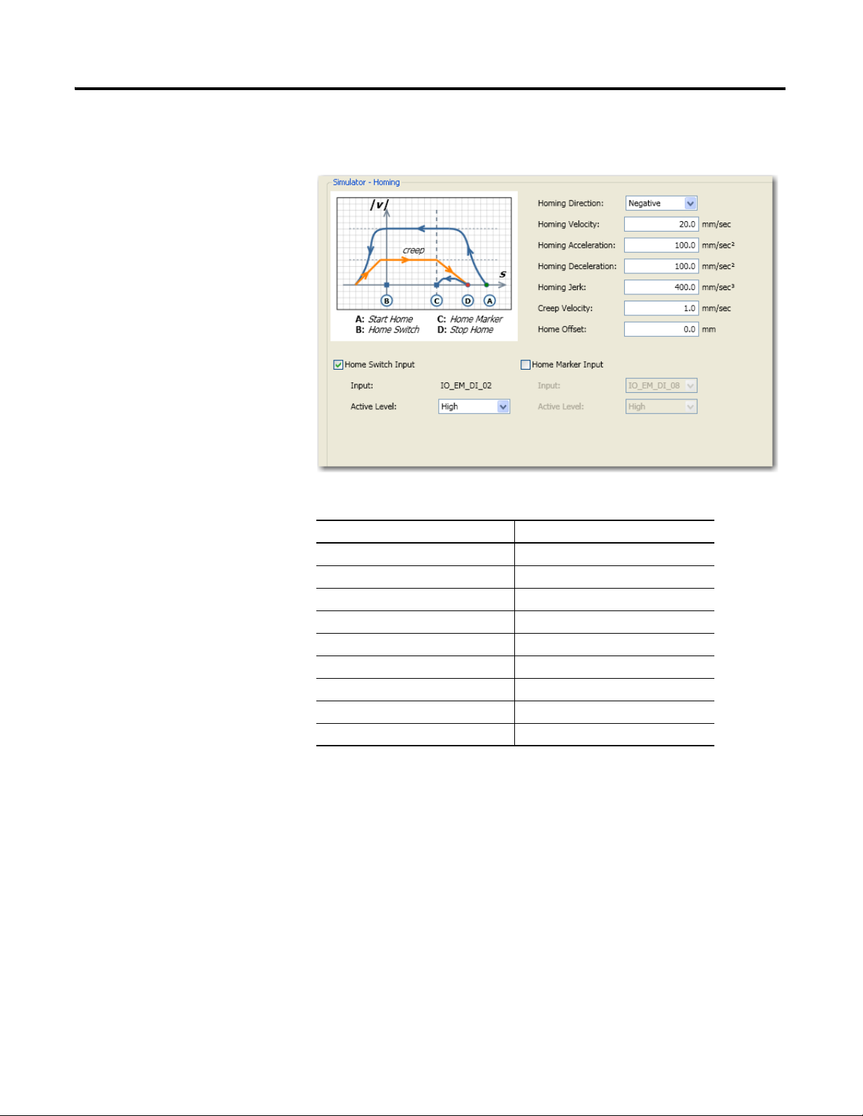
Configure Homing Properties
1. Under Motion, click Homing to bring up the Homing properties tab.
2. Configure homing parameters as shown in the table.
Parameter Value
Homing Direction Negative
Homing Velocity 20 mm/sec
Homing Acceleration 100 mm/sec
Homing Deceleration 100 mm/sec
Homing Jerk 400 mm/sec
Creep Velocity 1.0 mm/sec
Home Offset 0.0 mm
Home Switch Input Tick option box to enable
Home Switch Input Active Level High
2
2
3
12 Publication 2080-QS001A-EN-E - January 2013
Configure Motion Axis Properties Chapter 2
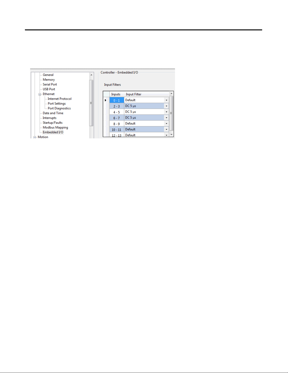
Configure Embedded I/O Properties
Go to Controller Properties → Embedded I/O, and update the input filter values as shown below.
Input filters are configured so that high speed pulse from the PTO is properly captured. When High Speed Counters and
Touch Probe are used, input filters need to be configured to match the high speed input.
Publication 2080-QS001A-EN-E - January 2013 13

Chapter 2 Configure Motion Axis Properties
Notes:
14 Publication 2080-QS001A-EN-E - January 2013

Chapter
3
Write Your Motion Control Programs
Introduction
In this chapter, you will write movement function block programs that will allow you to control the movement profile of
your axis.
Topic Page
Create Axis_PowerUp Program 17
Create Homing Program 21
Create Program for MC_MoveRelative 28
Create Program for MC_MoveAbsolute Function Block 31
Create Program for MC_MoveVelocity Function Block 36
Create Program for MC_TouchProbe Function Block 43
Before You Begin
Learn about motion control function blocks by referring to the Micro830 and Micro850 Programmable Controllers User
Manual, publication 2080-UM002
, and the Connected Components Workbench Online Help.
What You Need
• Connected Components Workbench revision 2 or later
• Firmware revision 2 and later for Micro830 controllers
15Publication 2080-QS001A-EN-E - January 2013 15
Loading...