


Schneider Electric REG 96, REG 24, REG 48 User Manual
EDMS xxxxxxxxx 03 2009
Zelio Control
Temperature controller
Quick start
04/2009
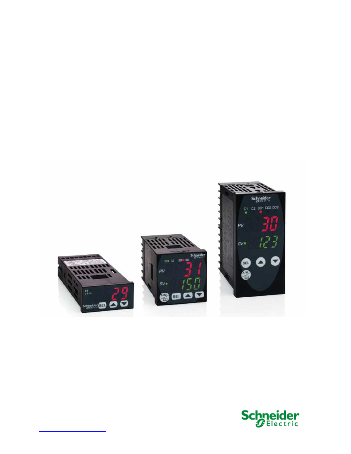
REG 24 ... REG 48 ... REG 96 ...
www.schneider-electric.com

Schneider Electric assumes no responsibility for any errors that may appear in this document. If you have any suggestions
for improvements or amendments or have found errors in this publication, please notify us.
No part of this document may be reproduced in any form or by any means, electronic or mechanical, including photocopying,
without express written permission of Schneider Electric.
All pertinent state, regional, and local safety regulations must be observed when installing and using this product. For
reasons of safety and to help ensure compliance with documented system data, only the manufacturer should perform
repairs to components.
When devices are used for applications with technical safety requirements, the relevant instructions must be followed.
Failure to use Schneider Electric software or approved software with our hardware products may result in injury, harm, or
improper operating results.
Failure to observe this information can result in injury or equipment damage.
© 2009 Schneider Electric. All rights reserved.
2
EIO0000000377 00 04/2009

SOMMAIRE
SOMMAIRE.........................................................................................................................................3
CHAPTER 1 INTRODUCTION............................................................................................................5
Fonctioning:...................................................................................................................................5
Application examples:...................................................................................................................5
Identification and functionnalities: Chapter 1 Introduction .....................................................6
CHAPTER 2 : TERMINOLOGY...........................................................................................................7
PID : Proportionnel Intégral Dérivé :.............................................................................................7
The outputs:...................................................................................................................................8
Regulation principle: .....................................................................................................................9
CHAPTER 3: EXAMPLES OF INTEGRATED FUNCTIONS INTO THE CONTROLLERS................11
Auto tunning: ...............................................................................................................................11
Fuzzy logic:..................................................................................................................................11
Self control :.................................................................................................................................11
Ramps: Chapter 3 Example of functions................................................................................12
Pid 2 :............................................................................................................................................12
Soft start :.....................................................................................................................................12
Alarms: .........................................................................................................................................12
CHAPTER 4 : WIRING AND SCHEMATICS :...................................................................................13
REG 24 (12 models) :..................................................................................................................13
REG 48 (14 models) :...................................................................................................................13
REG 96 (14 models): Chapter 4 wiring and shematics...........................................................14
CHAPTER 5: IMPLEMENTATION....................................................................................................15
Selection guide:...........................................................................................................................15
Front face description : Chapter 5 Implementation...............................................................16
CHAPTER 6: EXAMPLE OF IMPLEMENTATION............................................................................17
1 st step : Controller selection....................................................................................................17
2sd step : The cabling .................................................................................................................17
3 Rd step : Front face programming Chapter 6 Example of implementation .......................18
Probe type setting (PT100)..........................................................................................................18
Setting of the PT100 probe range (0 to 400°C)...... .....................................................................19
Setting of the minimum value for the PT100 probe Pvb = 0°C............................................ ......19
Setting of the maximum value for the PT100 probe PvF = 400°C.......................................... ...19
Chapter 6 Example of implementation ....................................................................................... 20
Setting of the choosen decimal value (Pvd) (to display the tenth)........................................... 20
Chapter 6 Example of implementation ....................................................................................... 21
Regulation mode selection = heating on channel 1 (rEv)..........................................................21
Alarms 1 and 2 parameters setting.............................................................................................21
Alarm 1 parameters setting at 32°C Chapter 6 Example of implementation.........................22
Alarm 2 setting at 38°C............................ ....................................................................................22
Parameter setting of the alarms on high overtaking (do1T) .....................................................22
4 Th step: Functional test............................................................................................................23
1 St step: install the software ZelioControl Soft (compatible with Windows XP and Vista) ...23
2 Nd step: installation of the TSXCUSB485 driver.....................................................................23
3 Rd step: connect the TSXUSB485 to your PC and the controller.......................................... 23
4 Th step : check the communication port parameters of the TSXCUSB485 driver................24
5 Th step: Discover the software ZelioControl Soft...................................................................24
Chapter 6 Example of implementation ....................................................................................... 25
6 Th step: check the communication parameters of the TSXCUSB485 driver.........................25
7 Th step: Communication parameters setting:.........................................................................25
Chapter 6 Setup example ............................................................................................................26
8 Th step: Connection to the régulator and application Upload...............................................26
9 Th step: Application display ....................................................................................................26
CHAPITRE 7: ZelioControl SOFT software....................................................................................27
ZelioControl Soft screen - oPE CH1 ...........................................................................................27
EIO0000000377 00 04/2009
3

ZelioControl SOFT screen PID CH2............................................................................................27
ZelioControl SOFT screen PID CH2............................................................................................28
ZelioControl Soft screen - PLT CH3............................................................................................29
ZelioControl Soft screen - PRG CH4...........................................................................................30
ZelioControl Soft screen - MON Ch5..........................................................................................31
ZelioControl Soft screen – SET Ch6...........................................................................................32
ZelioControl Soft screen – SyS Ch7........................................................................................... 33
ZelioControl Soft screen – ALM Ch8.......................................................................................... 34
ZelioControl Soft screen - CoM CH9...........................................................................................35
ZelioControl Soft screen - PFb CH10..........................................................................................35
ZelioControl Soft screen - PAS CH11.........................................................................................36
ZelioControl Soft screen - CFG CH13.........................................................................................37
Application file saving under ZelioControl SOFT......................................................................38
4
EIO0000000377 00 04/2009

CHAPTER 1 INTRODUCTION
Fonctioning:
The temperature control relays are equiped with a sensor input that permits to use multiple types of
sensors (PT100 probe, thermocouple, current or voltage sensors depending the model), one or two
process outputs (relay, solid state relay interface or analog) for heating, cooling or heating and
cooling regulation based on PID algorithm.
The measured temperature and the setpoint can be displayed in °Celsius or °Fahrenheit.
Advanced functions are embedded: Ramps (up to 16), hysteresis, fuzzy logic, auto tuning, soft
start, alarms.
The temperature controllers can be setup using the front face interface or through a common
software by a communication port and the integrated Modbus.
This communication port provides intergartion capability in an itelligente architecture supervised by
Magelis terminal or controled by PLCs(Twido, M340 or Premium) to exchange setpoints, process
values and alarms.
Application examples:
The temperature controllers Zélio control REG provide a solution for temperature control in the
following applications:
- Ovens and furnaces,
- Extrusion lines,
- UV &laser technologies,
- Cabin of painting,
- Cold rooms,
- Horticultural and livestock farms,
- Maintening the temperature of a colour bath…
- Plastic and rubber presses,
- thermo-forming,
- Production of synthetic fibres an polymerisation,
- Food and drink processing lines,
- Moulding presses,
- Environmental chambers, overhead furnaces and test benches,
EIO0000000377 00 04/2009
5

Identification and functionnalities:
The product part number allows identification of the embedded functions:
Chapter 1 Introduction
24 controllers :
REG
24 P TP 1 A R HU
P UJ L LU
J
Regulator
P = PID
Input type: TP = Thermocouples and PT100
UJ = Analog signal
Modbus function: A = no modbus available
Output type: R = relay
L = solid state relay interface
J = analog (4/20mA)
Power supply: HU = 110/220 VAC
LU = 24 V AC/DC
Size
PID Input Output Without Output power
type
number modbus type supply
48/96 controllers :
REG
48 P UN 1 L R HU
96 2 L LU
J
Regulator
Input type: UN = universal input thermocouple / PT100 / analog
Output type: R = relay
L = solid state relay interface
J = analog (4/20mA)
Modbus function: L = no modbus available
Power supply : HU = 110/220 VAC
LU = 24 V AC/DC
Note : When 2 outputs possible combination between 1 relay and 1 solid state relay interface or 1
solid state relay and one current (for detail see doc 24480-EN page 6)
Size
P = PID
PID Input
type
Output Without Output Power
number modbus type supply
6
EIO0000000377 00 04/2009
CHAPTER 2 : TERMINOLOGY
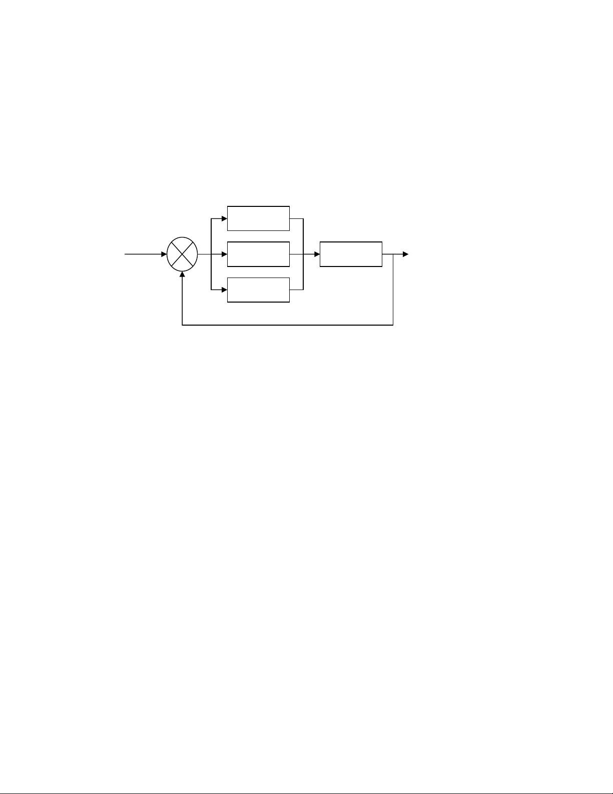
PID : Proportionnel Intégral Dérivé :
The principle of the PID algorithm consists on 3 actions that are dependant to the difference
between the setpoint (SV) and the measured process value (PV).
- A proportional action ne action proportionnelle, the error is multiplied by a gain GR
- A complete action, the error is integrated on an interval of time TI
- Derivated action, the error is derivated according to time TD
Consigne
SetPoint (SP)
+
-
Gr
1/Ti
Process
Td
Mesure
Process value (PV)
PID principle schematic
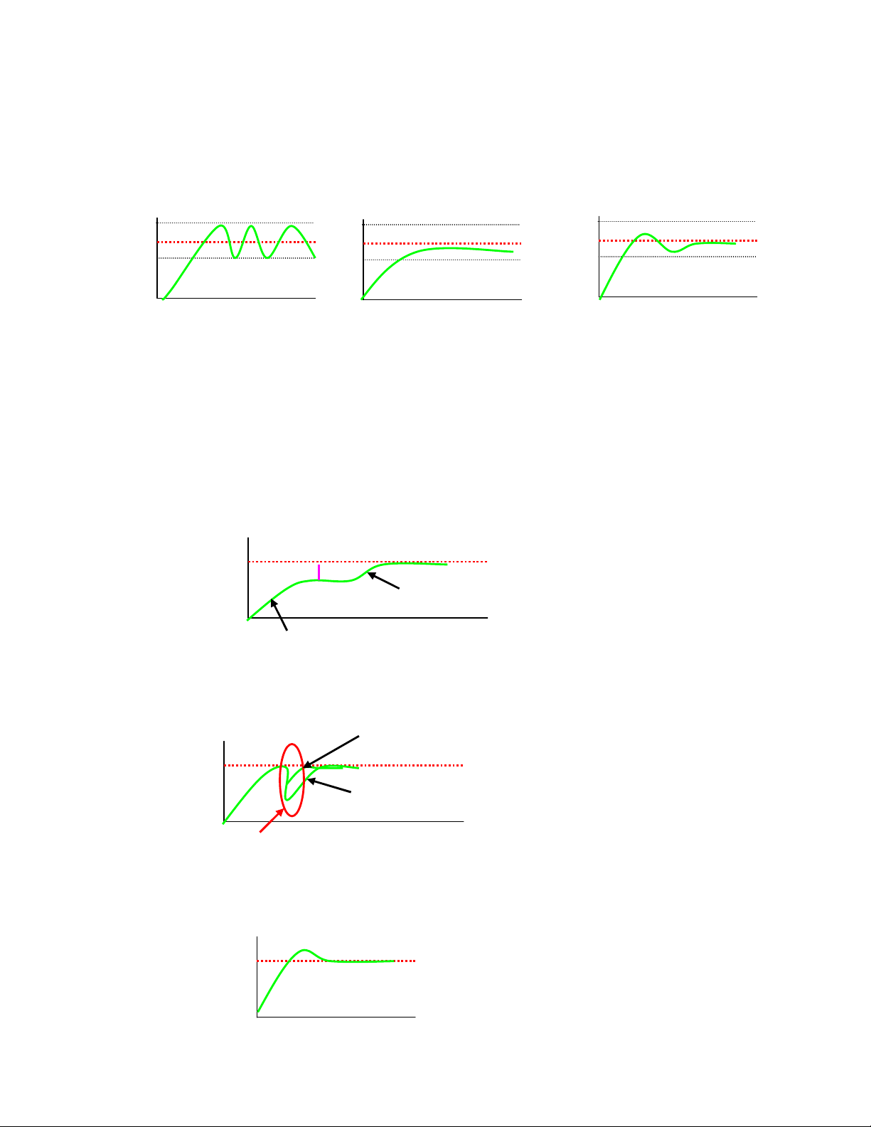
The parameters of the PID influence the answer of the system in the following way:
- When the proportional gain GR increases, the time of rise is shorter but there is a more
important overshoot of the setpoint. The time of stabilization varies little and the static error is
improved.
- When 1 / TI increase, the time of rise is shorter, but there is a more important overtaking of the
setpoint. The time of stabilization stretches out but we assure a static no error.
- When TD increases, the time of rise changes little, but the overshoot decreases. The time of
stabilization is better and there is no influence on the static error.
Introduction
EDMS xxxxxxxxx 03 2009
The use of 24/48/96 controllers is going to allow through a parameter setting of variables to appeal
to automatic functions or manual regulations.
These variables are going to allow:
- To choose the type of sensor used (probe thermocouple or PT100, analogical sensor),
- To choose the type of output used according to the actuator(s) (relay, solid state relay,
analogical),
- To choose the function of regulation (heating or cooling or heating and cooling),
- To reduce the time of establishment (the value of measure reaches as quickly as possible the
setpoint),
- Avoid overshoot (fuzzy logic and PID2),
- To maintain the temperature very close to the setpoint (réduction of the hysteresis and the dead
band),
- Avoid influence of perturbation,
- To activate alarms (high, low, delayed…),
- Setup ramps (up to 16 depending the model) to chain cycles of regulations,
- To have information of defects (overflowing measures, defect sensors),
- To lock or authorize the modification of the parameters from the front face of the product.
EIO0000000377 00 04/2009
7
Chapter 2 Terminology
The outputs:
- Relay : Output type mostly used
- Solid state relay interface: Used to contrôle actuator with no noise or frequent switching.
-
Courant : used to drive analog actuator such as speed drives
On and OFF control: Most simple algorithm, no anticipation of the setpoint, not precized, we notice
a lot of oscillations.
Proportional control: The process output is proportional to the derivation from the. The
proportional band allows overshoots anticipation.
Proportional control
SV
PV
Proportional band
8
EIO0000000377 00 04/2009
:
Regulation principle
Chapter 2 Terminology
Proportional
SV
PV
P too low =
oscillations
Intégrale
SV
PV
Derivative
SV
PV
External perturbation
PID
Offset
P
SV
PV
P too high = slow rise
and important gap
PI
Proportional + derivative
Proportional only
The integral allow catching up the
setpoint when there is an offset with
the process value.
In combination with the proportional,
the integrale function reaches the
setpoint.
The derived control allows countering
any distance created by an external
perturbation.
SV
PV
P correct = correct
rise and minor gap
SV
PV
EIO0000000377 00 04/2009
The combination of proportional,
derivative and integrale optimized
the regulation
9
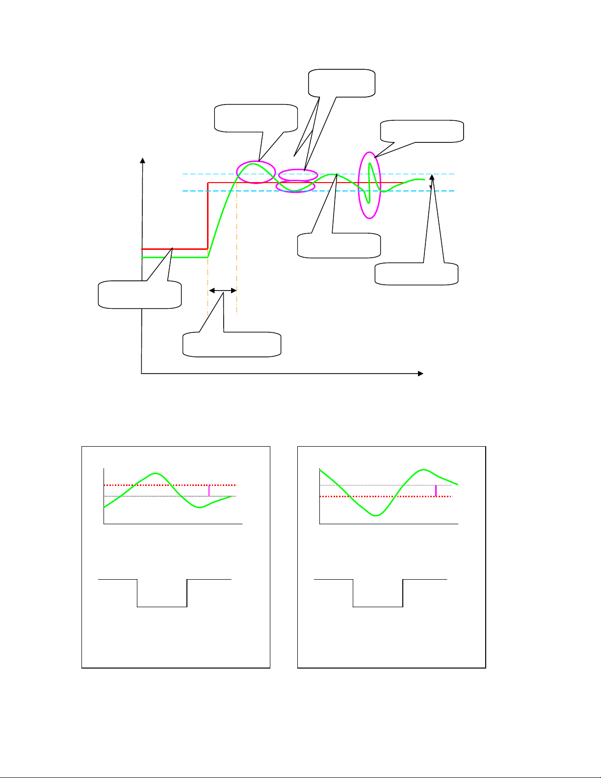
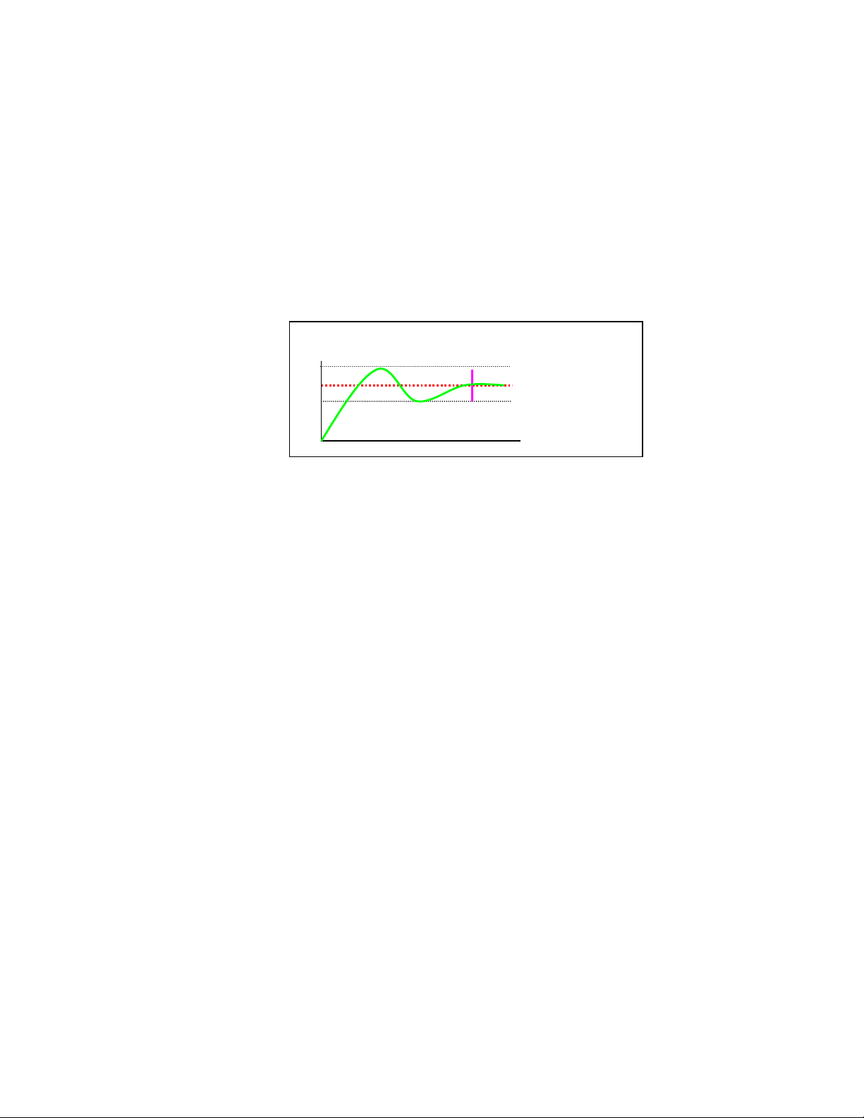
Visualization of PID structure:
Chapter 2 Terminology
Hystérésis Hysteresis
Overshoot
Perturbation
Values
PV (measure)
SP (setpoint)
Dead band
Response time
Visualization of PID structure Time
Reverse operation (heat control)
SV
PV
hys
Normal operation (cooling control)
PV
SV
hys
ON
PV<SV
ON
PV>SV
OFF
PV>SV
OFF
PV<SV
Output state
Output state
Choice of regulation type
10
EIO0000000377 00 04/2009

CHAPTER 3: EXAMPLES OF INTEGRATED FUNCTIONS INTO THE
CONTROLLERS
Auto tunning:
This function calculates automatically the proportional, derivative and integrale factors of the PID
function. This calculation is done during 2 regulation cycles.
Fuzzy logic:
The fuzzy logic manages the command of the process in a range of 0 to 100% of the measure
scale. This logic applies a command to the process to optimize the switching between heating and
cooling outputs depending the setpoint and avoid overshoot.
.
100%
Fuzzy logic principle
Heating Cooling
0%
Setpoint
Temperature
Self control :
This function restarts the calculation of the PID parameters at each setpoint change or after a
power on.
Remark: This command will generate temporarly a perturbation of the regulation close to the
setpoint value. Some applications might be sensitive to this function.
EIO0000000377 00 04/2009
11
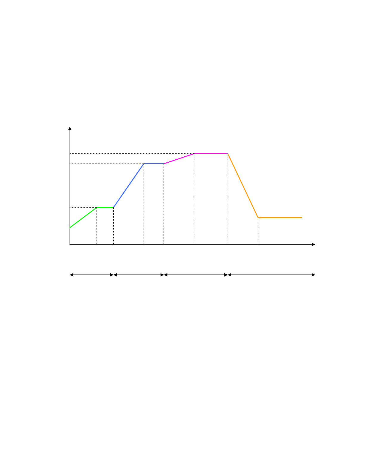
Ramps:
Chapter 3 Example of functions
This function allows a sequence of setpoints (up to 16 ramps for REG48 and REG96) during a
certain period of time. For each setpoint, a response time and the duration of the level can be
setup.
These times can be defined in hour and minutes or in minutes and seconds.
Example:
TM1r TM1s TM2r TM2s TM3r TM3s TM4r TM4s
Ramp 1 Ramp 2 Ramp 3 Ramp 4
Pid 2 :
Choice of a PID that avoid overshoot during the regulation phase.
Soft start :
Moderate starting up, the time of establishment (the process value reaches the setpoint) is
adjustable. This function can be used in the case of machines sensitive to the abrupt variations of
temperature.
Alarms:
One to 3 alarms are available depending the models. Each alarm is based on an output relay
(1 to 3A depending the model). Two more alarms are available through Modbus on REG96 and one
on the REG48 models.
The alarms can be configured for a low or high level and can also be delayed.
12
EIO0000000377 00 04/2009
 Loading...