


Product
Selection
Guide
SmartStruxure™ solution
Integrated building management system

SmartStruxure™ solution includes
software, hardware, engineering and
services that enable you to monitor,
measure, and optimize your building’s
performance throughout its life cycle
— saving energy while saving money
and increasing occupant satisfaction.
SmartStruxure solution facilitates the
exchange and analysis of data from
energy, lighting, fire safety and HVAC
because you can’t control what you
don’t measure.
I2

I3
Real world requirements
Our customers need to optimize their operations and energy consumption,
enhance occupant comfort and productivity, future-ready aging facilities,
and have anytime, anywhere access to their building systems.
So they got smart…
SmartStruxure solution
Real simple. Real smart. Real performance.
I3
Real simple. Real smart. Real performance.
Your job is complicated — SmartStruxure solution helps you simplify by delivering the right information
when, where, and how you want it.
> Personalized user interfaces
> Anytime, anywhere access and mobile apps
> Simplified day-to-day operations and engineering
> Attractive, user-friendly HTML graphics
SmartStruxure solution is a smart investment for today’s needs and tomorrow’s challenges. You can start
new or modernize, and expand from a single building to a global enterprise.
> Scalable system based on native open protocols
> Flexible, IP-enabled architectures
> System-to-system, and system-to-device integration
> IoT-ready and secure
SmartStruxure solution delivers an efficient enterprise by optimizing your building’s performance and
saving up to 30% or more of your energy costs.
> Optimize energy and operational performance
> Maintain occupant comfort and increase facility value
> Actionable intelligence across all building systems
> Connected services for enhanced performance and peace of mind
Building’s Digital Hub
Service
Efficiency
Architecture
Integration
Efficiency
Engineering
Efficiency
Control
Efficiency
Information
Efficiency
One global platform
Secure, connected, open
Engineering Efficiency
• Lower labor costs to design, build, install & maintain
• Lowe
Integration Efficiency
• Lower cost and easy to integrate
• S
• L
Service Efficiency
• Simplify system modernization
• O
Information Efficiency
• Customize reports and user interfaces
•
Control Efficiency
• Competitive & reliable control infrastructure
• E
r project risk
ystem-to-system & system-to-device integration
everage Schneider Electric-wide solutions
ptimize energy, asset and space usage
V
isualize analytics and big data
asy to install
Schneider Electric SmartStruxure Solution
I4

Table of Contents
SmartStruxureTM Solution
Software ...............................................S2
User Interfaces .......................................... S4
Automation Server Family of Modules ........................S6
SmartX Controller – AS-P ..................................S6
Power Supply and Module Terminal Bases ....................S7
Power Supply Selection Table ..............................S7
I/O Modules ............................................. S8
I/O Modules - Inputs and Outputs .......................... S12
SmartX Controller – AS-B ................................. S14
SmartX Controller – AS-BL ................................ S15
SmartX Controller – AS-B & AS-BL - Inputs and Outputs ........ S16
Accessories ........................................... S17
SmartX Controller – AD .................................. S17
Reference Architecture .................................. S17
LonWorks® Controllers
Xenta™ Series .......................................... L2
Xenta Series Controllers ................................... L3
Xenta Series Programmable Controllers ...................... L7
Xenta Series I/O Modules .................................L11
Xenta Series Controllers - Inputs and Outputs .................L13
Xenta Series Programmable Controllers - Inputs and Outputs .....L15
Xenta Series I/O Modules - Inputs and Outputs ................L16
MNL Series .............................................L17
MNL Series Controllers ...................................L18
MNL Series Controllers - Inputs and Outputs ................. L22
BACnet® Controllers
BACnet b3 Series ........................................B2
b3 Series Controllers .....................................B3
b3 Series xP Expansion I/O Modules .........................B9
b3 Series Controllers - Inputs and Outputs ...................B12
b3 Series xP Expansion I/O Modules - Inputs and Outputs ..... B15
MNB Series ........................................... B16
MNB Series Controllers .................................. B17
MNB Series Controllers – Inputs and Outputs ................B19
Additional EcoBuilding Resources
Digital Resources ........................................A2
Modernize with SmartStruxure .............................A3
Smart Building Service Plans ...............................A4
Control Devices ..........................................A5
SmartStruxure Lite .......................................A6
Room Controllers ........................................A7
Power Manager for SmartStruxure ...........................A8
Engineering Efficiency Tools ................................A9
AdaptiApps ............................................ A10
Quick Links ............................................ A11
Disclaimers
Not all products in the guide may be available in every country, please check availability with the local Schneider Electric office.
•
•
Some product images are not images of the exact model, but are represented by a “series” image.
•
Information within this guide is subject to change without notice.
• Schneider Electric is not responsible for inadvertent typographical errors or omissions.
I5

S1
S
n
Flexible, personalized user
workspace
SmartStruxure solution provides an attractive, modern interface that can
be organised by individual users to suit their needs. These preferences
follow users regardless of where they log on. The information each user can
access, such as graphics and alarms, can be managed at the job function,
or individual level for added security and accountability.
chneider Electric Smar tStrux ure Soluti o
Schneider Electric SmartStruxure Solution
S1
Software
StruxureWare™ Building Operation
StruxureWare Building Operation, the software that powers SmartStruxure solution, provides integrated monitoring, control, and
management of energy, lighting, fire safety, and HVAC. It is a centralized system with distributed intelligence that optimizes
facility performance. It is easy-to-use with robust functionality that leverages prior investments with Schneider Electric.
The Enterprise Server is the Windows
data for aggregation and archiving, yet is flexible enough to run stand-alone applications. It also serves as a single point of
administration through WorkStation, WebStation and Mobile Applications. Reports Server software is included with the Enterprise
Server and enables advanced reporting capabilities*.
WorkStation is the interface where users and engineers access their Automation Servers and Enterprise Servers. You can view
and manage graphics, alarms, scheduling, trend logs, and reports. Engineers can configure and maintain all aspects of the
StruxureWare Building Operation software.
WebStation provides a built-in, portable, fully functioning user interface to access the Automation and Enterprise Servers using a
web browser. Users can view and manage graphics, alarms, schedules, trend logs, and reports as well as create, edit, or remove
user accounts.
Technician Tool Mobile Application is a user interface for day-to-day operation of StruxureWare Building Operation software. It
can connect to Automation Servers and Enterprise Servers, and provides easy access to the system from anywhere in the world.
Users can view and manage values, alarms, schedules, and trend logs lists.
Web Services enable systems to easily connect with one another and share information securely across the internet using
standard HT TP and XML-based protocols. Examples: weather forecasts and utility prices.
EcoStruxure™ Web Services provide common and easy integration between Schneider Electric products. It has additional
functionality, including browse the other system’s exposed objects, Read/Write real time values, receive and acknowledge active
alarms, read historical (trend log) data. They can be used with third parties if the standards are implemented.
®
application version of a StruxureWare Building Operation Server that collects site-wide
SmartDriver is a custom driver that allows connection with other intelligent building devices that use non-native protocols
(available with StruxureWare Building Operation v1.8.1 and later versions).
Part Number Product Name Description
Enterprise Server
SXWSWESXX00001 SW-ES -BAS E-0 Enterpr ise Ser ver license fo r a PC server, includes Repor ts Ser ver license
WorkSt ation**
XWSWWORK00001 SW-STATION-STD-0 WorkStation Standard, 1 concurrent user license
S
kStat ion Professional, 1 concurrent user license. Professional Work Station ve rsion includes Editor lice ns-
SXWSWWORK00002 SW-STATION-PRO-0
SXWSWEDIT00001 SW-EDITORS-0
Add-ons
SXWSWEWSX00001 SW-E WS-1 EcoStruxure Web Service s (run-time) opt ion – Consume only
SXWSWEWSX00002 SW-E WS-2 EcoStruxure Web Service s (run-time) opt ion – Serve & Consume
SXWSWEWSX00003 SW-E WS-3 EcoStruxure Web Service s (run-time) opt ion – Serve & Consume, plu s Historical trend log data
SXWSWGWSX00001 SW-GWS-1 Web Services (Generic Consume) option
Lo
nWorks Co ntrol
Networking Software
SXWSWLNSX00001 SW-O PEN-LN S-SER VER Activat ion Key for OpenLNS Ser ver
e
chnician Tool M obile App
T
SXWSWMAPP00001 SW- MAP-1 Technician Tool Mobile Application, 1 concurrent user license
SXWSWMAPP00002 SW- MAP-2 Technician Tool Mobile Application, 10 concurrent users license
SXWSWMAPP00003 SW- MAP-3 Technician Tool Mobile Application, 25 concurrent users license
SXWSWMAPP00004 SW-MAP-4 Technician Tool Mobile Application, unlimited concurrent users license
rtDriver
Sma
SXWSWSDRV00001 SW-SM ARTDRI VER-1 Communi cation to external devic es via Smar tDriver, for one SmartD river
Wor
ing (Includes TGML Graphics editor, Function Block & Script Progr amming)
Pr
ogramming & Graphic s Editor licensing, 1 concur rent user license. TGML Gr aphics editor, Function Block
& Script Programming l icense only (Used for adding to existing WorkStation S tandard license)
* The Enter prise Server is BACn et B-OWS a nd B-BC certifie d; the testing for this cer tification included the use of Stru xureWare Buil ding Operat ion WorkStation as the H MI.
** Note: Th ere is no par t number for Web Station; it i s a default feature of the Automation Ser ver and Enterprise Ser ver (with no ne ed for additional licens ing)
.
S2
Software
(continued)
Power Manager for SmartStruxure is an embedded software module that enables energy usage to monitored, managed and
optimized in the same system as HVAC, lighting and fire safety. Designed specifically for non-electrical experts in buildings with
non-critical power needs. (Not available in all regions.)
AdaptiApps Custom User App Development Kit is a cloud-based solution to design and deploy customizable apps for end users
to increase satisfaction and productivity. With AdaptiApps, users have a simple, personalized app designed specifically for their
individual roles, giving them access to monitor and control systems and equipment relevant to them. AdaptiApps consists of two
parts: 1) Design & Deployment cloud-based environment for system integrators; 2.) Multiplatform Shell App to host apps for site
occupants.
Part Number Product Name Description
Power Man ager for
SmartStruxure
PSWPMNCZZSPEZZ Power Manager Base
Device Licensing - A la Carte
PSWDENCZZNPEZZ PME Entr y-Ran ge Device
PSWDMNCZZNPEZZ PME Mid- Range Device
PSWDSNCZZNPEZZ PME High -Range D evice
Adapti Apps - Mandatory
Part Numbers
SXWADPACC10001 AdaptiApps project creation
SXWADPDEP10010 A pp deployme nt (up to 10 devices) (*)
SXWADPDEP10050 App deploy ment (up to 50 devic es) (*)
SXWADPDEP10100 A pp deployme nt (up to 100 devices) (*)
SXWADPDEP10500 App deployment (up to 500 devices) (*)
SXWADPDEP10999 App deployment (unlimited devices) (**)
AdaptiApps - Optional
Part Numbers
SXWADPDES10005 Ready to deploy Apps of 1- 5 pages
SXWADPDES10010 Ready to deploy Apps of 6-10 pages
SXWADPDES10999 Ready to deploy Apps of 11+ pages
SXWADPWID10001 Specific widget development A dedicated service to design custom Widgets for branches/partners.
N/A Widget software development kit (SDK)
SXWADPPRE10001 End User App deployment on premise
P
ower Manager soft ware module license for a PC s erver
(no maintenance subscription included)
Adapti Apps Design license (1 proje ct). A project has a unique name, is d edicated to a cu stomer
and might ha ve differe nt revisions .
deployment license is needed to deploy AdaptiApps projects on devices. This license is man-
A
dator y for the first year and optional after ward: the lic ense is strongly recomm ended when using
BYOD deployment process It provides support for the latest devices (OS, new equipment) and
deployment of new versions of the App. Several deployment licenses can be linked to a single
project to fit the exact number of deployed devices.
A ‘ready to deploy’ project for branches/partners who don’t want to spend time designing a
User App.
he Adapti Apps Wid get SDK for br anches/pa rtners who want to be autonomous and d evelop their
T
own Widgets – Available on request (A daptiAppsRequest @schneider-electric.com)
IT
expertise for setting up on-premise deployment server, for projects which cannot be deployed
from the cloud for cybe rsecuri ty reason s
(*) Only supported by Managed Device / BYOD Customized deployment method.
(**) Sup ported by M anaged Device / BYOD Customized and Gener ic: this requires an unlimited devices deployment license.
Note: Smar tStruxure does r equire use of the EcoStruxure™ Web Services (EWS) interfac e for communic ations wit h AdaptiApps. However, purchase of the EWS addon option is not require d for use with A daptiApps.
Schneider Electric SmartStruxure Solution
S3
User Interface
Functionality matrix
WorkStation Standard - WorkStation software without graphics editor, script and function block programming editors.
WorkStation Pro - WorkStation software including graphics editor, script and function block programming editors.
WebStation - Direct access to an Automation Ser ver and/or Enterprise Server using a web browser.
WebReports - Direct access to the Reports Server using a web browser.
Mobile App: Technician Tool - Direct access to an Automation Server and/or Enterprise Server using a mobile application.
• Full funct ionality
o Partial functionality
Alarms
View alarms ••• •
Manage alarms • • •
it alarms • • o *2
Ed
Create alarms ••
Support for flas hing & audib le alarms ••
BACnet
View pr iority a rray •••
it prio rity ar ray •••
d
E
Create devices (includes device discovery) ••
Manag e BACnet backup and resto re ••
Graphics
View Graphics •••
eate and edit grap hics •
r
C
Logs & Ex tended Lo gs
View logs •
Ed
it logs • • o *4
Create logs • • o *5
View extended logs •••
Edit extended logs • • o *4
Create extended logs ••
LON
Create devices (includes device discovery) ••
a
nage devices ••
M
View Ne twork Vari ables (NVs) an d
Configuration Parameters (CPs)
Edit NVs an d CPs • • • • *6
Modbus
Create devices ••
Ma
nage devices ••
View values ••• •
Edit values ••• •
Point Values - e.g. Temperature Setpoint
View values •••
dit valu es - e.g. "chan ge setpoi nt" ••• •
E
Programs
Create and edit customised programs •
i
ew graphical func tion bloc k viewer ••
V
Program MNL/MNB controllers
WorkStation
Standard
• • • • *6
WorkStation Pro WebStation WebReports
• • • *3
Mobile App:
Technician Tool
o *1
•
WorkPlace
Tech Editor
• *7
* 1 Supports alarm acknowledgement.
* 2
Edit alar m ranges, tex t, delay tim es, shunt var iables, as signments, d eadband.
View in li st format.
* 3
* 4 Chan ge parameter s - e.g. inter val time.
* 5
Create in terval lo g type.
NVs and CP s are displaye d only in SI unit s.
* 6
MicroS oft Visi o required
* 7
S4
User Interface
Functionality matrix, continued
• Full funct ionality
o Partial functionality
Reports
View reports ••••
it reports • • • *8 •
Ed
Create & configure reports ••
Administer reports •
Schedules & Calendars
View schedules and calendars •••
Edit schedules and calendars • • o *9
Create schedules and calendars ••
Users & Us er Groups
Create a nd edit use rs •
Create a nd edit use r's group m embersh ip • • o *10
Create a nd edit groups ••
Create a nd edit per missions ••
User Experience
View customised workspaces •••
L
og on as windows Active Directory user •••
Automatic guest account log on •
Password management •••
Create a nd edit save d searches ••
View saved search •••
Ad hoc sea rch •••
Kiosk mode •
Bookmarking to a particu lar web view ••
Support for loc alisation ••• •
Support for tra nslatio n • • *11 • o *12 •
Abili ty to chang e languag e on the clie nt
side
Other
Configu re & edit I/O p oints, fie ld buses, and
c
ommunication ports
Create a nd edit log ical str ucture ••
Create a nd edit vie wers, panels and
workspaces
View & configure Watch pane • • o *13
View events •••
Administer backup/restore of database ••
Manage archiving ••
WorkSt ation
Standard
•••
••
••
WorkStation Pro WebStation WebReports
• o *10
Mobile App:
Technician Tool
•
9
o *
* 8 Edit so me paramete rs per repo rt, save cha nges or make a co py of the repor t with changes .
Edit exist ing only; ca nnot create or e dit recur ring calend ar events.
* 9
*10 Canno t assign per missions .
*11 Translat ion is only sup ported in t he WorkSt ation inter face; it is not supp orted for g raphics an d programmi ng editors .
*12 Repor t text can be edite d and transl ated using a Rep ort Defi nition Lan guage (RDL) e ditor such as Mi crosoft ® Repor t Builder.
*13 Confi guration ch anges cann ot be saved.
Schneider Electric SmartStruxure Solution
S5
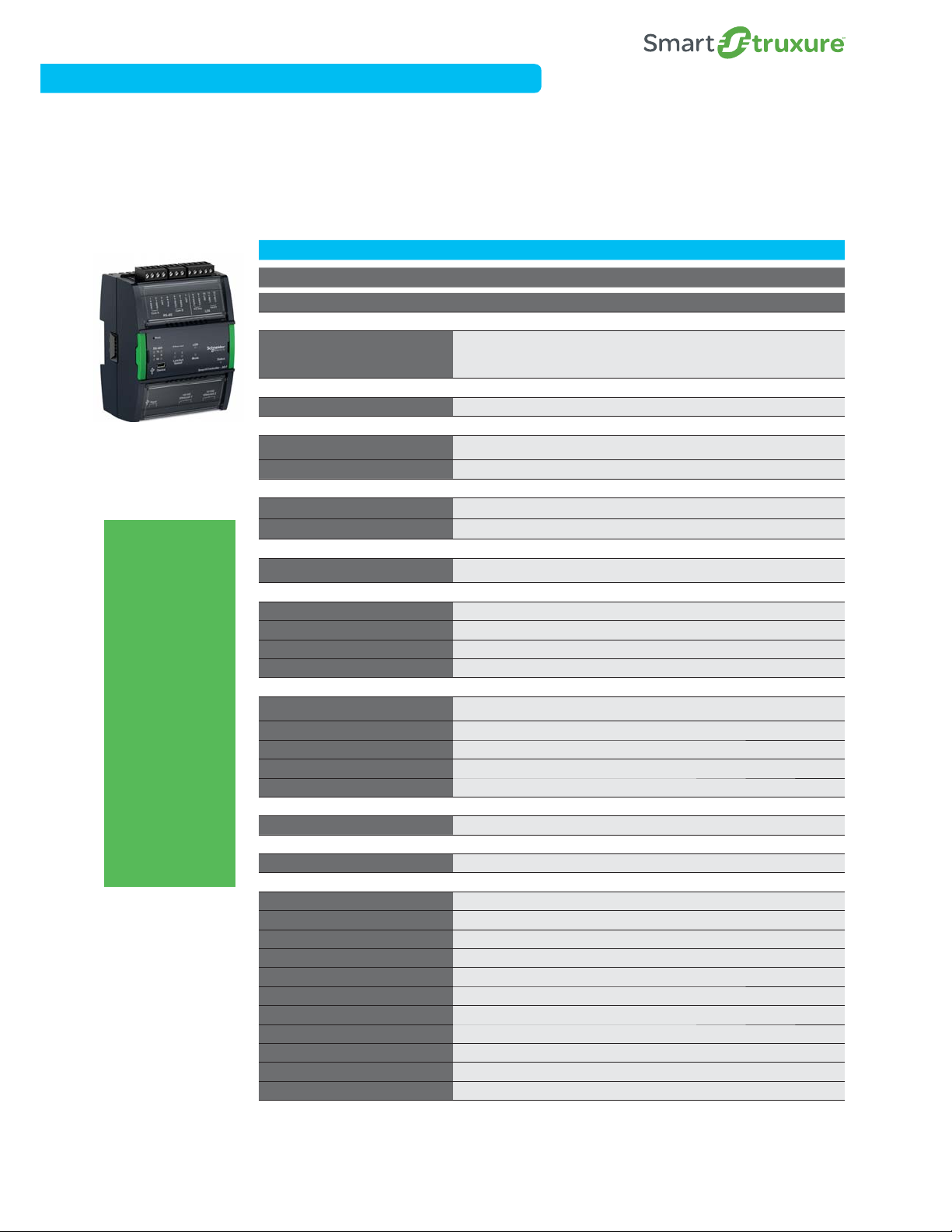
Automation Server Family of Modules
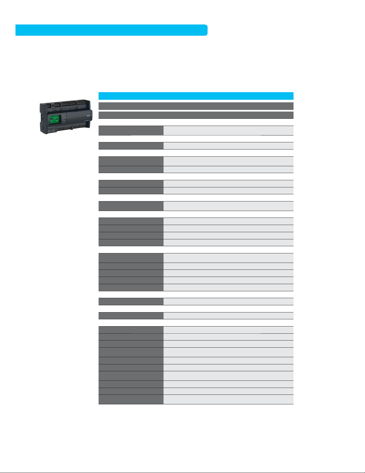
SmartX Controller – AS-P
The SmartX Controller – AS-P is a SmartStruxure server device at the Automation Server Level of the architecture. With superior
performance, the AS-P can be used in place of the Automation Server in any application. It simplifies system integration and
transition, and is the preferred choice for large, complex enterprise applications. It also enhances integration performance of
offers such as Connected Services, Power Manager for SmartStruxure, and AdaptiApps custom user apps.
AS-P ASP-SMK
Part Number SXWASPXXX10001 SWXASPXXX1S001
Communications
LonWorks FTT-10, BACnet/IP, BACnet MS/
TP, Modbus TCP (Client+Server), Modbus
serial ( Master+Slave), EW S, Generic
WebSevice consume
90 W x 114 H x 6 4 D mm
(3.60 W x 4.5 0 H x 2.50 D in.)
0°C to 50 °C (32°F to 122° F) 0-95% RH
(non-condensing)
Eco Friend ly ABS/PC, UL94 5VB, IP 20 (<12.5
mm protection)
Smar tX Contr oller – AS- P
The future
of building
management is
here!
The Smart X
Controller – AS-P
and AS-B feature
dual Ethernet
ports to elevate
BACnet field bus
communication
to the IP level.
Modernize the
BMS while keeping
in place legacy
field buses and
devices to futureready current
systems and move
buildings into the
21st century!
LonWorks FTT-10, BACnet/IP, BACnet MS/
, Modbus TCP (Client+Server), Modbus
Communication Interface
Software
Programability Function Block/Script Programmable Function Block/Script Programmable
Physical
Dimensions
Weight (including baseplate) 0.245 kg (0. 54 lb) 0.245 kg (0.5 4 lb)
Power
Power 24 VDC 24 VDC
Consumption 10 W 10 W
Environmental
Opera ting Rang e
CPU Internals
CPU SPEAr320S, ARM926 core SPEAr320S, ARM926 core
Memory 4 GB 4 GB
Battery
Real time clock Yes -30 days backup/Sup er Capacitor Yes -30 days backup/Super Capacitor
External Features
Enclosure rating
HOA Switches (DO/AO) N/A N/A
Manual Override of Outputs N/A N/A
Digit al Status L EDs Yes Yes
Service Port Yes Yes
Ter min als
I/O Exp ansion Yes - Up to 29 modul es/464 ma x I/O Yes - Up to 29 modules/4 64 max I/O
External Enclosure/Mounting
Mounting
Certifications
BTL Yes Yes
FCC 47 CFR § 15, Class B (Emissi on) 47 CFR § 15, Class B (Emis sion)
Industry Cand a (IC) ICES-003 (Emission) ICES -003 (Emission)
UL UL-916 (Energy Management Equipment) UL-916 (Energy Management Equipment)
C-UL US Yes Yes
CE - EU Yes Yes
WEEE - Di rective of the Europe an Union Yes Yes
RoHS Directive Yes Yes
RCM Yes Yes
US Patent 8 207 842, 8 271 102, 7 99 4 438 8 207 8 42, 8 271 102, 7 994 43 8
UL-864 No Yes
*Notes: SmartSt ruxure solution installations or BM S transitions requiring UL-864 cer tifications must use the S martX Controller
AS- P-SMK (listed above).
SmartX Controller - AS- P and AS- B conform to t he BACnet
BACnet Testing Laboratories (BTL
TP
serial ( Master+Slave), EW S, Generic
WebSevice consume
90 W x 114 H x 6 4 D mm
(3.60 W x 4.5 0 H x 2.50 D in.)
0°C to 50 °C (32°F to 122° F) 0-95% RH
(non-condensing)
No No
Eco Friend ly ABS/PC, UL94 5VB, IP 20 (<12.5
mm protection)
DIN- rail or wall mount DIN- rail or wall mount
®
®
). Strux ureWare™ Building Operation v1.9 is the certified firmware revision.
Building C ontroller (B-BC) profile at protocol r evision 12 by the
S6
Automation Server Family of Modules
Power Supply and Module Terminal Bases
The PS-24V is a power supply module that accommodates 24 VAC or 24 VDC input power. Each power supply module delivers
reliable and consistent output power of 24 VDC to the backplane. It can deliver power to the AS-P and a number of I/O modules
calculated from the Power Budget Table (located below). If more I/O modules are needed, another power supply can be added to the
bus. The power supplies are isolated from each other while also providing communication pass-through.
Part Number Product Name Description
SXWPS24VX10001 PS-24V Power S upply 24 VAC or 21-30 V DC
SXWTBPSW110001 TB- PS-W1 Terminal Base Power Supply (Terminal Ba se required for each power supply)
SXWTBASW110002 TB-AS P-W1 Terminal B ase AS- P (Terminal bas e required fo r each AS- P)
SXWTBIOW110001 TB-IO-W1 Terminal Base I/O (Terminal B ase required for each I/O module)
Automation Server Power Supply
PS-24V
NOTE: An appropriate terminal base is required for each module, including the AS-P, Power Supply
and I/O Modules. See the above table for the correct part numbers.
I/O Modu le
Terminal Bas e and Module Detail
Power Selection Table
Power Requirements
Smar tX Controller – AS-P
Smar tX Controller – AS-B
Power Requirement s - Input only I /O
DI-16 1.6 W
RTD-DI-16 1.6 W
UI-16 1.8 W
Power Requirement s - Output only I/O
DO-FA-12 1.8 W
DO-FA-12-H 1.8 W
DO-FC-8 2.2 W
DO-FC-8- H 2.2 W
AO-8 4.9 W
AO-8-H 4.9 W
AO-V- 8
AO-V- 8-H
wer Requirements - M ixed I/O
Po
UI-8/DO-FC-4 1.9 W
UI-8/DO-FC-4-H 1.9 W
UI-8/AO-4 3.2 W
UI-8/AO-4-H 3. 2 W
UI-8/AO-V-4 1.0 W
UI-8/AO-V-4-H 1.0 W
24 VDC / 10 W
24 VDC / 10 W 24 VAC / 15 VA
24 VDC Powe r
24 VDC Powe r
0.7 W
0.7 W
24 VDC Powe r
Please refer to the appropriate Dat a Sheets for more information.
Schneider Electric SmartStruxure Solution
S7
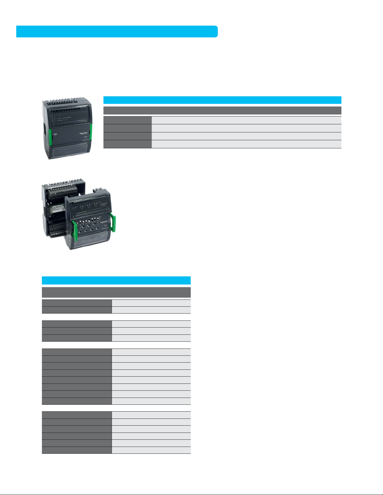
Automation Server Family of Modules
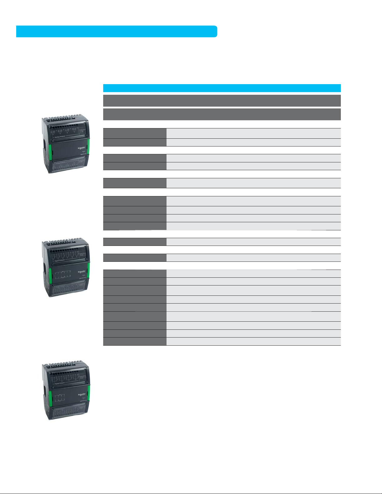
I/O Modules
The Automation Server includes support for a broad spectrum of I/O modules. The variety of modules available ensures the right
combination of points for any project, which keeps costs down for our customers. Some modules are available with Hand/Off/Auto
(HOA) switches to provide override control of the outputs.
UI-16
16 Channel Un iversal Inp ut
DI-16
16 Channel Digital Input
UI-16 DI-16
Part Number
Physical
Dimensions
Weight (including baseplate) 0. 269 kg (0.59 lb.) 0. 255 kg (0.56 lb.) 0.279 kg (0.62 lb.)
w
er
Po
Power 24 VDC 24 VDC 24 VDC
Consumption 1.8 W 1.6 W 0.7 W
ental
Environm
Opera ting Rang e
External Features
Enclosure rating
HOA Switches (DO/AO) No No Available on -H model
Digital Status LEDs Yes Yes No
Service Port No No No
Ter
mi nal s
I/O Terminals Terminal base Terminal base Terminal base
ernal Enclosure/Mounting
Ext
Mounting DIN -rail or w all mount DIN-rail or w all mount DIN-rail o r wall mount
ifications
Cert
FCC 47 CFR § 15, Cla ss B (Emission) 47 CFR § 15, Class B (Emission) 47 CFR § 15, Class B (Emission)
Industry Canada (IC) ICES-003 (Emission) ICES-003 (Emiss
UL
C-UL US No No No
CE - EU Yes Yes Ye s
WEEE - Di rective of the Europe an
Union
RoHS Directive Yes Yes Ye s
RCM Yes Yes Ye s
US Patent 7 994438 7 9 94438 7 99 4438
SXWUI16XX10001 SXWDI16XX10001
9 0 W x 11 4 H x 6 4 D m m
(
.60 W x 4.50 H x 2.50 D in.)
3
0 °C to 50 °C (32 ° F to 122 °F)
0
95% RH (non-condensing)
-
Eco Friend ly ABS/PC, UL94 5VB,
P 2
0 (<12.5 mm protection)
I
UL-916 (Energy Management
uipment)
Eq
Yes Yes Yes
9 0 W x 11 4 H x 6 4 D m m
(3.60 W x 4.5 0 H x 2.50 D in.)
0 °C to 50 °C (32 ° F to 122 °F)
0-95% RH (non-condensing)
Eco Friend ly ABS/PC, UL94 5VB,
IP 20 (<12.5 mm protection)
ion) ICES -003 (Emission)
UL-916 (Energy Management
Equipment)
9 0 W x 11 4 H x 6 4 D m m
(3.60 W x 4.5 0 H x 2.50 D in.)
0 °C to 50 °C (32 ° F to 122 °F)
0-95% RH (non-condensing)
Eco Friend ly ABS/PC, UL94 5VB,
IP 20 (<12.5 mm protection)
UL-916 (Energy Management
Equipment)
AO-8,
AO-8-H
SXWAO8XXX10001,
SXWAO8HXX10001
AO-8 , AO-8-H
8 Channel A nalog Out put
S8
Automation Server Family of Modules
I/O Modules, continued
Part Number
Physical
Dimensions
Weight (including baseplate) 0. 279 kg (0.62 lb.) 0. 317 kg (0.70 lb.) 0.332 kg (0.73 lb.)
wer
Po
Power 24 VDC 24 VDC 24 VDC
Consumption 0.7 W 1.8 W 2.2 W
vironmental
En
AO-V-8 , AO-V-8- H
8 Channel A nalog Out put
Volta ge Poin ts
DO-FA-12 , DO-FA-12-H
12 Channel Digital Output,
Form-A
Opera ting Rang e
External Features
Enclosure rating
HOA Switches (DO/AO) Available on -H model Available on -H model Available o n -H model
Digital Status LEDs No Yes Yes
Service Port No No No
Te
rm ina ls
I/O Terminals Terminal base Terminal base Terminal base
ternal Enclosure/Mounting
Ex
Mounting DIN -rail or w all mount DIN-rail or w all mount DIN-rail o r wall mount
tifications
Cer
FCC 47 CFR § 15, Cla ss B (Emission) 47 CFR § 15, Class B (Emission) 47 CFR § 15, Class B (Emission)
Industry Canada (IC) ICES-003 (Emission) ICES-003 (Emis
UL
C-UL US No No Yes
CE - EU Yes Yes Ye s
WEEE - Di rective of the Europe an
Union
RoHS Directive Yes Yes Ye s
RCM Yes Yes Ye s
US Patent 2002/96/EC 2002 /96/EC 2002/96/EC
A
O-8-V,
AO-8-V-H
SXWAOV8XX10001,
SXWAOV8HX10001
9 0 W x 11 4 H x 6 4 D m m
(
3.60 W x 4.5 0 H x 2.50 D in.)
0 °C to 50 °C (32 ° F to 122 °F)
0
-95% RH (non-condensing)
Eco Friend ly ABS/PC, UL94 5VB,
P 20 (<12.5 mm protection)
I
UL-916 (Energy Management
quipment)
E
Yes Yes Yes
DO-FA-12,
DO-FA-12-H
SXWDOA12X10001,
SXWDOA12H10001
9 0 W x 11 4 H x 6 4 D m m
(3.60 W x 4.5 0 H x 2.50 D in.)
0 °C to 50 °C (32 ° F to 122 °F)
0-95% RH (non-condensing)
Eco Friend ly ABS/PC, UL94 5VB,
IP 20 (<12.5 mm protection)
sion) ICES -003 (Emission)
UL-916 (Energy Management
Equipment)
9 0 W x 11 4 H x 6 4 D m m
(3.60 W x 4.5 0 H x 2.50 D in.)
0 °C to 50 °C (32 ° F to 122 °F)
0-95% RH (non-condensing)
Eco Friend ly ABS/PC, UL94 5VB,
IP 20 (<12.5 mm protection)
UL-916 (Energy Management
Equipment)
DO-FC-8,
DO-FC-8-H
SXWDOC8XX10001,
SXWDOC8HX10001
DO-FC-8, DO-FC-8 -H
8 Channel D igital Out put,
Form-C
Schneider Electric SmartStruxure Solution
S9

Automation Server Family of Modules
I/O Modules, continued
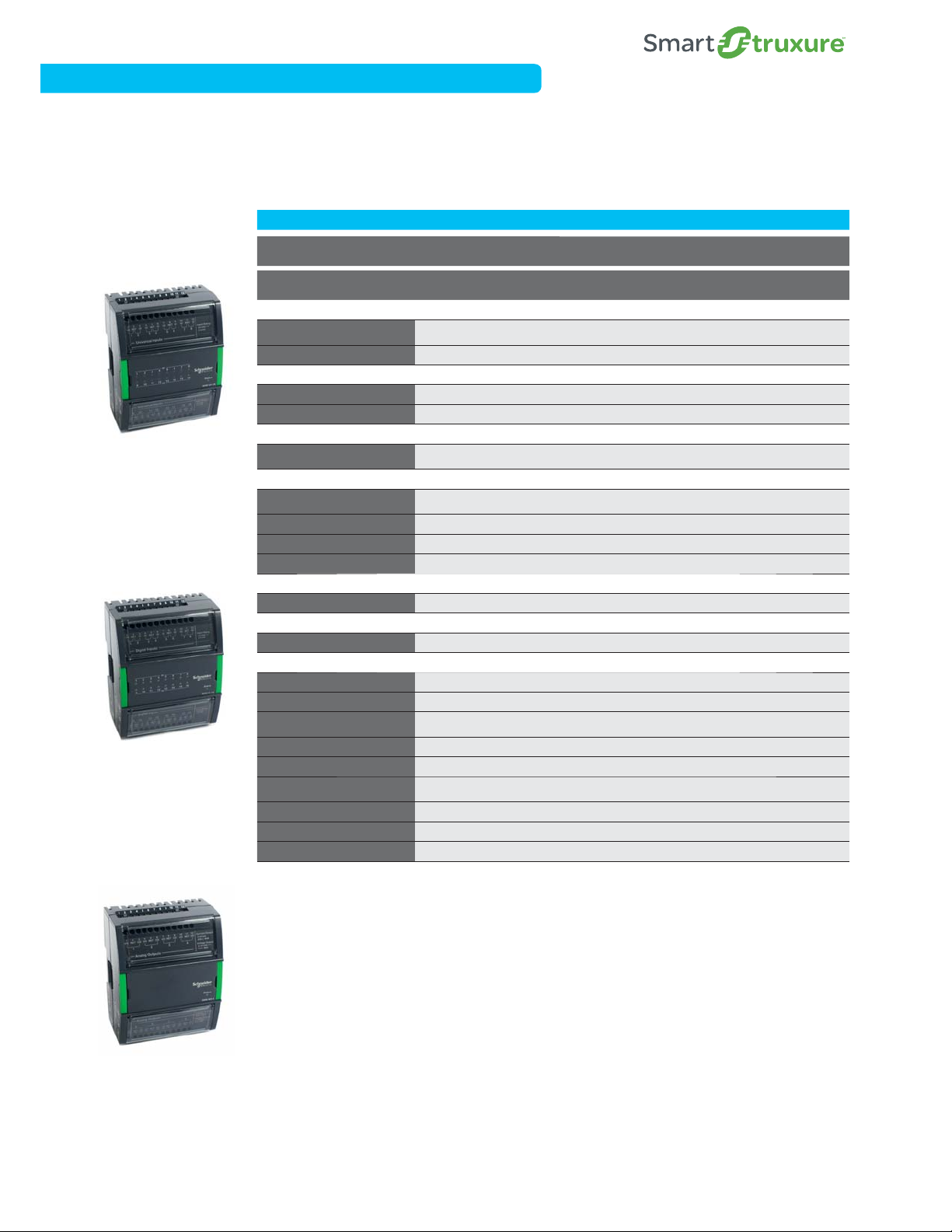
UI-8/AO-4, U I-8/AO -4- H
8 Channel U niversal In puts
with 4 An alog Outpu ts
UI-8/AO-V-4, UI-8/AO-V-4-H
8 Channel U niversal In puts
with 4 Cha nnel Voltage
Outputs
(UI-8/AO-V-4 -H shown)
-8/AO-4,
UI
UI-8/AO-4-H
Part Number
Physical
Dimensions
Weight (including baseplate) 0. 276 kg (0.61 lb.) 0. 276 kg (0.61 lb.) 0.304 kg (0.67 lb.)
w
er
Po
Power 24 VDC 24 VDC 24 VDC
Consumption 3.2 W 1.0 W 1.9 W
ental
Environm
Opera ting Rang e
External Features
Enclosure rating
HOA Switches (DO/AO) Available on -H model Available on -H model Available o n -H model
Digital Status LEDs Yes Yes Yes
Service Port No No No
Ter
mi nal s
I/O Terminals Terminal base Terminal base Terminal base
ernal Enclosure/Mounting
Ext
Mounting DIN -rail or w all mount DIN-rail or w all mount DIN-rail o r wall mount
ifications
Cert
FCC 47 CFR § 15, Cla ss B (Emission) 47 CFR § 15, Class B (Emission) 47 CFR § 15, Class B (Emission)
Industry Canada (IC) ICES-003 (Emission) ICES-003 (Emiss
UL
C-UL US Yes Yes Yes
CE - EU Yes Yes Ye s
WEEE - Di rective of the Europe an
Union
RoHS Directive Yes Yes Ye s
RCM Yes Yes Ye s
US Patent 7 994438 7 9 94438 7 99 4438
SXWUI8A4X10001,
SXWUI8A4H10001
9 0 W x 11 4 H x 6 4 D m m
(
.60 W x 4.50 H x 2.50 D in.)
3
0 °C to 50 °C (32 ° F to 122 °F)
0
95% RH (non-condensing)
-
Eco Friend ly ABS/PC, UL94 5VB,
P 2
0 (<12.5 mm protection)
I
UL-916 (Energy Management
uipment)
Eq
Yes Yes Yes
UI-8/AO-V-4,
UI-8/AO-V-4-H
SXWUI8V4X10001,
SXWUI8V4H10001
9 0 W x 11 4 H x 6 4 D m m
(3.60 W x 4.5 0 H x 2.50 D in.)
0 °C to 50 °C (32 ° F to 122 °F)
0-95% RH (non-condensing)
Eco Friend ly ABS/PC, UL94 5VB,
IP 20 (<12.5 mm protection)
ion) ICES -003 (Emission)
UL-916 (Energy Management
Equipment)
UI-8/DO-FC-4,
UI-8/DO-FC-4-H
SXWUI8D4X10001,
SXWUI8D4H10001
9 0 W x 11 4 H x 6 4 D m m
(3.60 W x 4.5 0 H x 2.50 D in.)
0 °C to 50 °C (32 ° F to 122 °F)
0-95% RH (non-condensing)
Eco Friend ly ABS/PC, UL94 5VB,
IP 20 (<12.5 mm protection)
UL-916 (Energy Management
Equipment)
UI-8/DO -FC-4, UI-8/DO -FC-4-H
8 Channel U niversal In puts with 4
Channel D igital Out puts, Form -C
S10
Automation Server Family of Modules
I/O Modules, continued
Part Number
Physical
Dimensions
Weight (including baseplate) 0. 269 kg (0.59 lb.)
wer
Po
Power 24 VDC
Consumption 1.6 W
vironmental
En
R T D - D I - 1 6
16 Channel Inputs (RTD and
Digital) Combination Module
Opera ting Rang e
External Features
Enclosure rating
HOA Switches (DO/AO) No
Digital Status LEDs Yes
Service Port No
rm ina ls
Te
I/O Terminals Terminal base
ternal Enclosure/Mounting
Ex
Mounting DIN -rail or wall mount
tifications
Cer
FCC 47 CFR § 15, Cla ss B (Emission)
Industry Canada (IC) ICES-003 (Emission)
UL
C-UL US Yes
CE - EU Yes
WEEE - Di rective of the Europe an
Union
RoHS Directive Yes
RCM Yes
US Patent 7 994438
RTD-DI-16
SXWRTD16X10001
9 0 W x 1 1 4 H x 6 4 D m m
(
3.60 W x 4.5 0 H x 2.50 D in.)
0 °C to 50 °C (32 ° F to 122 °F)
0
-95% RH (non-condensing)
Eco Friend ly ABS/PC, UL94 5VB, IP
2
0 (<12.5 mm protection)
UL-916 (Energy Management
E
quipment)
Yes
Schneider Electric SmartStruxure Solution
S11
Automation Server Family of Modules
I/O Modules - Inputs and Outputs
UI-16 DI-16
Part Number
Universal Inputs 16
Digital Contact
Digit al Counter - L ow Speed
Digit al Counter - M edium Speed
Digit al Counter - H igh Speed
Digital Supervised
Analog Voltage - 0-1 V
Analog Voltage - 0-5 V
Analog Voltage - 0-10 V
Analog Voltage - 2-10 V
Analog Current - 0 -20 mA
Analog Current - 4 -20 mA
Analog Resistance
Analog Thermis tor - 10 k
Analog Thermis tor - 1.8 k
Analog Thermis tor - 1 k
Analog Thermis tor - 20 k
Analog Thermis tor - 2.2 k
Analog RTD - Pt100
Analog RTD - Pt1000
Analog RTD - Ni1000
Analog RTD - LG Ni1000
Digital Inputs 16
Digital Contact
Counte r - Low Speed
Counte r - Medium Sp eed
Counte r - High Spee d
Digital Outputs 12 8
Form A, S PST
Form C, SPDT
Tri ac
Analog Outputs
Voltage - 0-10 V
rrent - 0 -20 mA
u
C
SXWUI16XX10001
x
x
x
x
x
x
x
x
x
x
x
SXWDI16XX10001
x
x
AO-8,
AO-8-H
SXWAO8XXX10001,
SXWAO8HXX10001
88
xx
x
AO-8-V,
AO-8-V-H
SXWAOV8XX10001,
SXWAOV8HX10001
DO-FA-12,
DO-FA-12-H
SXWDOA12X10001,
SXWDOA12H10001
x
DO-FC-8,
DO-FC-8-H
SXWDOC8XX10001,
SXWDOC8HX10001
x
S12
Automation Server Family of Modules
I/O Modules - Inputs and Outputs, continued
-8/AO-4,
UI
UI-8/AO-4-H
Part Number
Universal Inputs 88816*
Digital Contact
Digit al Counter - L ow Speed
Digit al Counter - M edium Speed
Digit al Counter - H igh Speed
Digital Supervised
Analog Voltage - 0-1 V
Analog Voltage - 0-5 V
Analog Voltage - 0-10 V
Analog Voltage - 2-10 V
Analog Current - 0 -20 mA
Analog Current - 4 -20 mA
Analog Resistance
Analog Thermis tor - 10 k
Analog Thermis tor - 1.8 k
Analog Thermis tor - 1 k
Analog Thermis tor - 20 k
Analog Thermis tor - 2.2 k
Analog RTD - Pt100
Analog RTD - Pt1000
Analog RTD - Ni1000
Analog RTD - LG Ni1000
Digital Inputs
Digital Contact
Counte r - Low Speed
Counte r - Medium Sp eed
Counte r - High Spee d
Digital Outputs 4
Form A, S PST
Form C, SPDT
Tri ac
Analog Outputs 44
Voltage - 0-10 V
urrent - 0-20 mA
C
SXWUI8A4X10001,
SXWUI8A4H10001
xxxx
xxxx
xxx
xxx
xxx
xxxx
xxx
xxx
xxx
xxx
xxx
xx
x
UI-8/AO-V-4,
UI-8/AO-V-4-H
SXWUI8V4X10001,
SXWUI8V4H10001
UI-8/DO-FC-4,
UI-8/DO-FC-4-H
SXWUI8D4X10001,
SXWUI8D4H100 01
x
RTD-DI-16
SXWRTD16X10001
x
x
x
x
Schneider Electric SmartStruxure Solution
S13
Automation Server Family of Modules
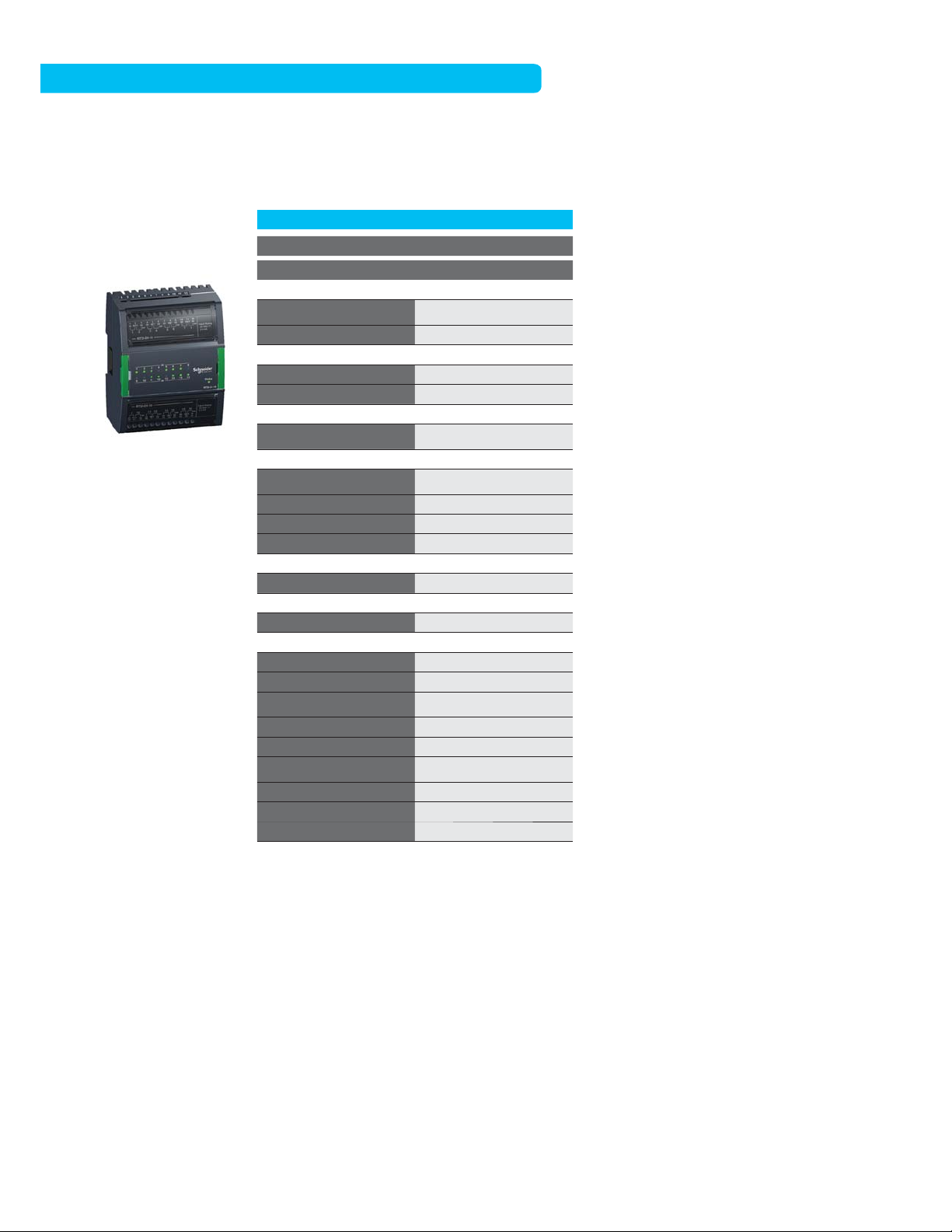
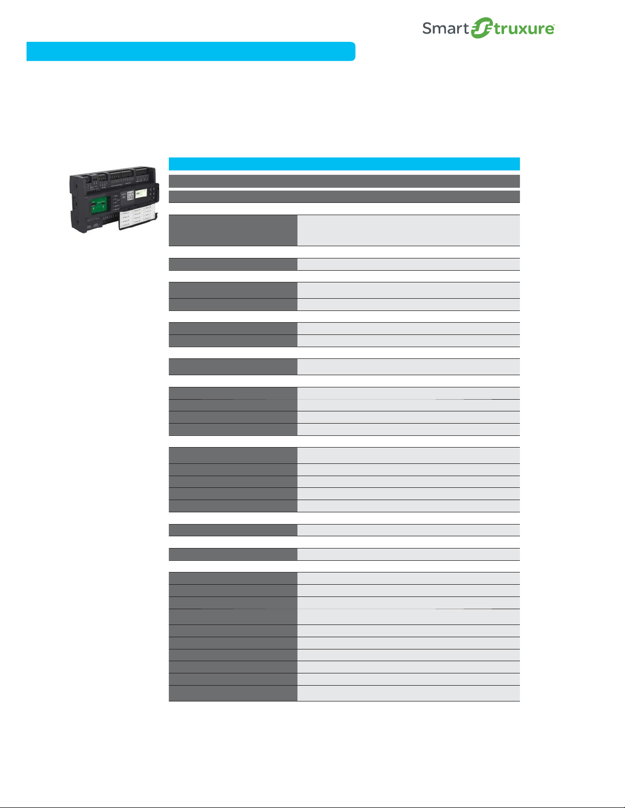
SmartX Controller – AS-B
The SmartX Controller – AS-B is the most compact, all-in-one BMS. It features flexible on-board universal I/O configurations
and built-in power supply. A SmartStruxure server device, its power ful, compact design is ideal for small-to-medium main plant
control applications. It offers lower total installation costs.
AS-B-24(H) AS-B-36(H)
Smar tX Contr oller – AS- B
Note: Screw terminal
blocks for the AS -B
and AS- BL must be
ordered separately.
Please find the
AS-B C onnector Kit
part number in the
Accessories section
on page S17.
Part Number
Communications
Communication Interface
Software
Programability Function Block/Script Programmable Function Block/Script Programmable
Physical
Dimensions
Weight (including baseplate)
Power
Power
Consumption
Environmental
Opera ting Rang e
CPU Internals
CPU
Memory
Battery
Real time clock
External Features
Enclosure rating
HOA Switches (DO/AO)
Manual Override of Outputs
Digit al Status L EDs
Service Port Yes Yes
Ter min als
I/O Exp ansion No No
External Enclosure/Mounting
Mounting
Certifications
BTL
FCC
Industry Cand a (IC)
UL
C-UL US
CE - EU
WEEE - Di rective of the Europe an Union
RoHS Directive
RCM
US Patent
SXWASB24(X,H)10001 SXWASB36(X,H)10001
BACnet/IP, BACnet MS/TP, Modbus
TCP (Client+Server), Modbus serial
(Master+Slave), EWS, Generic
WebSevice consume
1 9 8 W x 11 0 H x 6 4 D m m
(7
.8 W x 4.3 H x 2.5 D in.)
0.504 kg (1.111 lb)
24 VAC/DC
10 W
0°C to 50 °C (32°F to 122° F) 0-95% RH
(non-condensing)
SPEAr320S, ARM926 core SPEAr320S, ARM926 core
4 GB
No No
Yes -30 days backup/Sup er Capacitor Yes -30 days ba ckup/Sup er Capacitor
Eco Friend ly ABS/PC, UL94 5VB, IP 20
(<12.5 mm protection)
N/A
Yes - On 'H' mod el
Yes
DIN- rail or wall mount DIN- rail or wall mount
Yes Yes
47 CFR § 15, Class B (Emission) 47 CFR § 15, Class B (Emission)
ICES-003 (Emission)
UL-916 (Energy Management
Equipment)
Yes
Yes
Yes
Yes
Yes
8 207 842, 8 271 102,
7 994 438
BACnet/IP, BACnet
MS/ TP, Modbu s TCP (Client+Ser ver),
Modbus serial (Master+Slave), EWS,
Generic WebSevice consume
1 9 8 W x 11 0 H x 6 4 D m m
(7.8 W x 4.3 H x 2.5 D in.)
0.504 kg (1.111 lb)
24 VAC/DC
10 W
0°C to 50 °C (32°F to 122° F) 0-95% RH
(non-condensing)
4 GB
Eco Friend ly ABS/PC, UL94 5VB, IP 20
(<12.5 mm protection)
N/A
Yes - On 'H' mod el
Yes
ICES-003 (Emission)
UL-916 (Energy Management
Equipment)
Yes
Yes
Yes
Yes
Yes
8 207 842, 8 271 102,
7 994 438
*Notes: SmartSt ruxure solution installations or BM S transitions requiring UL-864 cer tifications must use the S martX Controller
AS- P-SMK (see page S6).
SmartX Controller - AS- P and AS- B conform to t he BACnet
BACnet Testing Laboratories (BTL
®
). Strux ureWare™ Building Operation v1.9 is the certified firmware revision.
®
Building C ontroller (B-BC) profile at protocol r evision 12 by the
S14
Automation Server Family of Modules
SmartX Controller – AS-BL
The SmartX Controller – AS-BL features a BACnet/IP-only communication interface, making it an ideal high-density IP-based
field controller. (Not available in all regions.)
AS-B-24(H)L AS-B-36(H)L
Smar tX Contr oller – AS- BL
Note: Screw terminal
blocks for the AS -B
and AS- BL must be
ordered separately.
Please find the
AS-B C onnector Kit
part number in the
Accessories section
on page S17.
Part Number
Communications
Communication Interface
Software
Programability Function Block/Script Programmable Function Block/Script Programmable
Physical
Dimensions
Weight (including baseplate) 0.504 kg (1.111 lb) 0.504 kg (1.111 lb)
Power
Power 24 VAC/ DC 24 VAC/ DC
Consumption 10 W 10 W
Environmental
Opera ting Rang e
CPU Internals
CPU S
Memory 4 GB 4 GB
Battery
Real time clock Y
External Features
Enclosure rating
HOA Switches (DO/AO) N/A N/A
Manual Override of Outputs Yes - On 'H ' model Yes - On 'H ' model
Digit al Status L EDs Ye s Yes
Service Port Ye s Yes
Ter min als
I/O Exp ansion No No
External Enclosure/Mounting
Mounting
Certifications
BTL
FCC
Industry Cand a (IC) ICES- 003 (Emission) ICES-0 03 (Emission)
UL
C-UL US Yes Yes
CE - EU Yes Yes
WEEE - Di rective of the Europe an
Union
RoHS Directive Yes Yes
RCM Yes Yes
US Patent
SXWASB24(X,H)10002 SXWASB36(X,H)10002
BACnet/IP, EWS, Generic WebSevice
consume
1 9 8 W x 11 0 H x 6 4 D m m
7.8 W x 4.3 H x 2.5 D in.)
(
0°C to 50 °C (32°F to 122° F) 0-95% RH
(non-condensing)
PEAr 320S, AR M926 cor e
No No
es -30 days backup/S uper CapacitorYes -30 days backup/S uper Capacitor
co Friendly ABS/P C, UL94 5V B, IP 20
E
(<12.5 mm protection)
DIN- rail or wall mount DIN- rail or wall mount
Yes Yes
47 CFR § 15, Class B (Emission) 47 CFR § 15, Class B (Emission)
UL-916 (Energy Management
Equipment)
Yes Yes
8 207 842, 8 271 102,
7 994 438
B
ACnet/IP, EWS, Generic WebSevice
consume
1 9 8 W x 11 0 H x 6 4 D m m
(7.8 W x 4.3 H x 2.5 D in.)
0°C to 50 °C (32°F to 122° F) 0-95% RH
(non-condensing)
S
PEAr 320S, AR M926 cor e
Eco Friend ly ABS/PC, UL94 5VB, IP 20
(<12.5 mm protection)
UL-916 (Energy Management
Equipment)
8 207 842, 8 271 102,
7 994 438
Schneider Electric SmartStruxure Solution
S15
*Notes: SmartSt ruxure solution installations or BM S transitions requiring UL-864 cer tifications must use the S martX Controller
AS- P-SMK (see page S6).
SmartX Controller - AS- P and AS- B conform to t he BACnet
BACnet Testing Laboratories (BTL
®
). Strux ureWare™ Building Operation v1.9 is the certified firmware revision.
®
Building C ontroller (B-BC) profile at protocol r evision 12 by the
Automation Server Family of Modules
SmartX Controller – AS-B & AS-BL – Inputs and Outputs
AS-B-24(H) AS-B-36(H) AS-B-24(H)L AS-B-36(H)L
Part Number
Universal Inputs/Outputs
Digital Contact
Digit al Counter - L ow Speed
Digit al Counter - M edium Speed
Digit al Counter - H igh Speed
Digital Supervised
Analog Voltage - 0-1V
Analog Voltage - 0-5V
Analog Voltage - 0-10V
Analog Voltage - 2-10V
alog Cur rent - 0-20mA UB I UB I UB I UB I
An
Analog Current - 4 -20mA
alog Resistance
An
Analog Thermis tor - 10k
Analog Thermis tor - 1.8k
Analog Thermis tor - 1k
Analog Thermis tor - 20k
Analog Thermis tor - 2.2k UA/UB I UA/UB I UA/UB I UA/UB I
Analog RTD - Pt100
An
alog RTD - P t1000
Analog RTD - Ni1000
Analog RTD - LG Ni1000
Digital Inputs 44
Digital Contact ••
unter - Lo w Speed
Co
Counte r - Medium Sp eed
Counte r - High Spee d
Digital Outputs 4848
Form A, S PST • 4 • 4
Form C, SPDT
PWM ••••
ia c
Tr
SXWASB24(X,H)10001 SXWASB36(X,H)10001 SXWASB24(X,H)10002 SXWASB36(X,H)10002
12-UA 4-UB 20-UA 8-UB 12-UA 4-UB 20-UA 8-UB
UA/UB I&O UA/UB I&O UA/UB I&O UA/UB I&O
UA/ UB I&O
UA/UB IUA/UB IUA/UB IUA/UB I
UA/UB IUA/UB IUA/UB IUA/UB I
UA/ UB I
UA/UB IUA/UB IUA/UB IUA/UB I
UA/UB IUA/UB IUA/UB IUA/UB I
UA/ UB I
UA/ UB I
UA/ UB I
UA/UB I&O UA/UB I&O UA/UB I&O
UA/ UB I UA/UB I UA/UB I
UA/ UB I UA /UB I UA /UB I
UA/ UB I UA /UB I UA /UB I
UA/ UB I UA /UB I UA /UB I
4 4
Key:
UA – Univer sal Type A
UB – Unive rsal Type B
I – Input
O – Outpu t
S16
Automation Server Family of Modules
n
S
B
B
oae)
oftware)
I/
Accessories
The following accessories are available for the Automation Server Family of modules.
Part Number Product Name Description
SXWDINEND10001 DIN -RA IL-CLI P-25 DIN-Rai l End Clip, packag e of 25 pieces
SXWTE RLBL10011 PRINTOUT-A4-W1
SXWTE RLBL10012 PRINTOUT-LTR-W1
SXWSCABLE10002 S-C ABLE-L-1.5M S-C able extension cord for Au tomation Se rver I/O bu s, L shaped con nectors, 1.5 m
SXWSCABLE10003 S-CABLE-L-0.75M S- Cable exten sion cable fo r Automation Server I/ O bus, L-shaped connectors, 0.75 m
SXWASBCON10001 AS-B connector kit Screw terminals for all AS-B models. Note: Ordered separately, not delivered with the controller
SXWASBINS10001 AS-B installer kit Dummy unit, no electro nics, just ter minals. Sup ports easy wiring in the panel shop
SXWUSBA DP10001
USB-485 -INET
Interface Adapter
SmartX Controller – AD (Advanced Display)
Portable or permanent-mount tablet HMI specifically configured to interact with Smar tStruxure solution user inter faces:
WebStation, Technician Tool and AdaptiApps.
A4- Size blank pr intable adhesive label sheets for ter minals
(100 Sheets, 18 labels per Sheet)
Letter-size blank pri ntable adhe sive label she ets for terminals
(100 Sheets, 16 labels per Sheet)
I/NE T Adapter: Seperate hardware component, added to a Smart X Control ler - AS-P or
Automation Server
Part Number Product Name Description
SXWADBUND10001 Advanced Display 10-inch Bundle Includes tablet, mounting frame, and bezel
SXWADUSBA10001 USB cable, 1.5 m (5 ft) For connection to A S-P or US B power adapter
SXWADUSBA10002 USB cable, 3.0 m (10 ft) For connection to AS -P or USB p ower adapter
SXWADUSBB10001 USB cable, Y-shaped, 1.5 m (5 ft) For connectio n to automation server and USB power ada pter
SXWADUSBB10002 USB c able, Y-shaped , 3.0 m (10 ft) For conne ction to autom ation ser ver and USB po wer adapter
Reference Architecture
Immersion
sensor
Globe valve
actuator
MG350C
actuator
StruxureWare
Building Operation
WorkStation
b3 controller
b3 controller
PICV
actuator
Current
b3 controller
switch
SE8000
room controller
SE7000
room controller
Power
supply
StruxureWare
u
Building Operation
WebStation
AS-P
speed drive
power meter
power meter
BACnet MS/TP
Modbus RTU
Variable
EM3500
Acti 9
Acti 9
SmartLink
I/O modules
Xenta
controller
Xenta
controller
Xenta
controller
3rd-party LON
controller
SE7000
room controller
LON FTT-10
Advanced Display
showing
Mobile Apps:
Technician Tool and
AdaptiApps (Custom
User Apps)
MNB controller
MNB controller
3rd-party
BACnet
controller
SE8000
room controller
EM4200 series
Enercept power meter
Enterprise and Automation Servers support:
Web Services (Generic Consume)
LonWorks
AS-P
Power
r
supply
BACnet MS/TP
®
/IP
BACnet
®
TCP
Modbus
EcoStruxure™ Web Services
®
/IP (Enterprise Server only)
I/O modules
Variable
speed drive
EM3500
power meter
Acti 9
power meter
Acti 9
SmartLink
Modbus RTU
Building Management
MNL
controller
MNL
controller
MNL
controller
SE7000
room controller
3rd-party
LON
controller
LON FTT-10
Current
switch
PICV
actuator
Ball valve
actuator
Enterprise Server
(software)
Duct
sensor
Damper
actuator
PM5500
series
meter
Reports Server
(software)
Immersion
sensor
Globe valve
actuator
PICV
actuator
MG350C
actuator
b3 controller
b3 controller
SE8000
room
controller
AS-B
BACnet MS/TP
StruxureWare
Building Operation
WebReports
AS-B
Variable
speed drive
Acti 9
power meter
Acti 9
SmartLink
Modbus RTU
Schneider Electric SmartStruxure Solution
S17

LonWorks Controllers
Schneider Electric SmartStruxure Solution
L1
L1

S
n
Xenta Series
Xenta series controllers and I/O modules provide an
open and flexible system architecture and access to
standardized LonWorks-based network technology.
chneider Electric Smar tStrux ure Soluti o
Schneider Electric SmartStruxure Solution
L2
Xenta Series
Xenta Series Controllers
Part Number
Communications
Protocol LonTalk® communication protocol LonTalk communic
Communication Interface T P/FT-10, 78 kbps T P/FT-10, 78 kbps T P/FT-10, 78 kbps
ware
Soft
Pre loaded Application/ASC Ye s Yes Ye s
cal
Physi
Xenta 102-B
VAV Zone Controller
Xenta 102- EF
VAV Zone Controller
Dimensions
Weight (including baseplate) 0.4 kg (0.88 lb.) 0.4 kg (0.88 lb.) 0. 4 kg (0.88 lb.)
w
er
Po
Power 24 VAC +20% -10%, 50/ 60 Hz 24 VAC +20% -10%, 50/60 Hz 24 VAC +20% -10%, 50 /60 Hz
Consumption
Environmental
Opera ting Rang e
External Features
Enclosure rating
HOA Switches (DO/AO) No No No
Digital Status LEDs No No No
Intelligent Sensors STR150 STR150 STR150
Service Port Xenta OP Xenta OP Xenta OP
Ter
mi nal s
I/O Terminals Fixed terminal Fixed terminal Fixed terminal
I/O Exp ansion No No No
ernal Enclosure/Mounting
Ext
Enclosure class N/A N/A N/A
Mounting DIN -rail or w all mount DIN -rail or wal l mount DIN- rail or wall mount
ifications
Cert
LonMark LonMark certifi ed: VAV 8010 LonMark cer tified: VAV 8010 LonMark certifi ed: VAV 8010
FCC 47 CFR § 15, Cla ss A (Emission) 47 CFR § 15, Class A (Emission) 47 CFR § 15, Class A (Emission)
UL
C-UL US Yes Yes Yes
CE - EU Yes Yes Ye s
WEEE - Di rective of the Europe an
Union
RoHS Directive Yes Yes Ye s
RCM Yes
102-B 102-EF 102-VF
007305310 007305330 007305350
ation protocol LonTalk comm unication p rotocol
127 W x 126 H x 50 D mm
.0 W x 4.9 H x 1.9 D in.)
(5
4 VA with Xent a OP, Actuato r
u
pply max 12 VA, Total max
s
16 VA
0 °C to 50 °C (32 ° F to 122 °F)
-
95% RH (non-condensing)
0
UL94 5 VB, IP 30 (<2.5 mm
t
ection)
pro
UL-916 (Energy Management
q
uipment)
E
Yes Yes Yes
127 W x 126 H x 50 D mm
(5.0 W x 4.9 H x 1.9 D in.)
4 VA with Xent a OP, Actuato r
supply ma x 12 VA, Total max
16 VA
0 °C to 50 °C (32 ° F to 122 °F)
0-95% RH (non-condensing)
UL94 5 VB, IP 30 (<2.5 mm
protection)
UL-916 (Energy Management
Equipment)
s
Ye
127 W x 126 H x 50 D mm
(5.0 W x 4.9 H x 1.9 D in.)
4 VA with Xent a OP, Actuato r
supply ma x 12 VA, Total max
16 VA
0 °C to 50 °C (32 ° F to 122 °F)
0-95% RH (non-condensing)
UL94 5 VB, IP 30 (<2.5 mm
protection)
UL-916 (Energy Management
Equipment)
Ye
s
Xenta 102-V F
VAV Zone Controller
L3

Xenta Series
Xenta Series Controllers, continued
Part Number
Communications
Protocol LonTalk communication protocol LonTalk communica
Communication Interface T P/FT-10, 78 kbps T P/FT-10, 78 kbps TP/FT-10, 78 kbps
tware
Sof
Pre loaded Application/ASC Ye s Yes Yes
ical
Phys
Xenta 102- ES
VAV Zone Controller
Xenta 102- AX
VAV Zone Controller
Dimensions
Weight (including baseplate) 0.4 kg (0.88 lb.) 1.04 kg (2.3 lb.) 0.4 kg (0.88 lb.)
wer
Po
Power 24 VAC ±20% , 50/60 Hz 24 VAC ±10%, 50/ 60 Hz 24 VAC +20% -10%, 50/60 H z
Consumption
Environmental
Opera ting Rang e
External Features
Enclosure rating
HOA Switches (DO/AO) No No No
Digital Status LEDs No No No
Intelligent Sensors STR150 STR150 STR150
Service Port Xenta OP Xenta OP Xenta OP
Te
rm ina ls
I/O Terminals Fixed terminal Two-piece terminal Fixed terminal
I/O Exp ansion No No No
ternal Enclosure/Mounting
Ex
Enclosure class N/A N/A N/A
Mounting DIN -rail or w all mount VAV/FPB box mount DIN- rail or wall mount
tifications
Cer
LonMark LonMark certifi ed: VAV 8010 LonMark cer tified: VAV 8010 LonMark cer tified: Chilled Ceiling
FCC 47 CFR § 15, Cla ss A (Emission) 47 CFR § 15, Class B (Emission) 47 CFR § 15, Clas s A (Emission)
UL
C-UL US Yes No Yes
CE - EU Yes Yes Yes
WEEE - Di rective of the Europe an
Union
RoHS Directive Yes Yes Yes
RCM Yes
127 W x 126 H x 50 D mm
5.0 W x 4.9 H x 1.9 D in.)
(
6 VA with Xent a OP, Digit al
O
Total max 120 VA
0 °C to 50 °C (32 ° F to 122 °F)
0
UL94 5 VB, IP 30 (<2.5 mm
pro
UL-916 (Energy Management
E
Yes Yes Yes
102-ES 102-AX 103-A
007305370 007305401 007305610
tion protocol LonTalk communication pro tocol
utputs max 6 x 9 =114 VA ,
-95% RH (non-condensing)
tection)
quipment)
159 W x 197 H x 63 D mm
(6.25 W x 7.75 H x 2.50 D in.)
9 VA, Digit al Output s each 12 VA ,
Total max 36 VA
0 °C to 50 °C (32 ° F to 122 °F)
0-9 0% RH (non- condensin g)
NEMA-1, UL94 5 VB, IP 10 (<50
mm protection)
UL-916 (Energy Management
Equipment)
Yes Yes
112 W x 110 H x 50 D mm
(4.37 W x 4.29 H x 2.00 D in.)
4 VA with Xent a OP, Actuato r
supply ma x 12 VA, max 2 x 19
VA=38 VA, Total ma x 54 VA
0 °C to 50 °C (32 ° F to 122 °F)
0-95% RH (non-condensing)
UL94 5 VB, IP 30 (<2.5 mm
protection)
UL-916 (Energy Management
Equipment)
Xenta 103-A
Chilled Ceiling Zone Controller
Schneider Electric SmartStruxure Solution
L4

Xenta Series
Xenta Series Controllers, continued
Xenta 104-A
Roof Top Zone Controller
Xenta 110-D/24, 110-D/23 0
Dual Zone Controllers
104 -A
Part Number
Communications
Protocol LonTalk communication protocol LonTalk communication protocol
Communication Interface TP/FT-10, 78 kbps TP/FT-10, 78 kbps
ware
Soft
Pre loaded Application/ASC Yes Ye s
cal
Physi
Dimensions
Weight (including baseplate) 0.4 kg (0.88 lb.) 0.3 kg (0.66 lb.)
w
er
Po
Power 24 VAC +20% -10%, 50/60 Hz
Consumption
Environmental
Opera ting Rang e
External Features
Enclosure rating
HOA Switches (DO/AO) No No
Digital Status LEDs No No
Intelligent Sensors STR150 STR150
Service Port Xenta OP Xenta OP
r
mi nal s
Te
I/O Terminals Fixed terminal Fixed terminal
I/O Exp ansion No No
ernal Enclosure/Mounting
Ext
Enclosure class N/A N/A
Mounting DIN-r ail or wall mount DIN- rail or wall mount
ifications
Cert
LonMark LonMark certifie d: Roof Top
FCC 47 CFR § 15, Class A (Emission) 47 CFR § 15, Class A (Emission)
UL
C-UL US Yes Ye s
CE - EU Ye s Ye s
WEEE - Di rective of the Europe an
Union
RoHS Directive Yes Ye s
RCM Yes
112 W x 110 H x 50 D mm
(
5 VA, digit al outputs m ax 4 x 19 VA,
ma
0 °C to 50 °C (32 ° F to 122 °F)
0-
UL94 5 VB, IP 30 (<2.5 mm
prot
UL-916 (Energy Management
Eq
Yes Ye s
007305910
.37 W x 4.29 H x 2. 00 D in.)
4
x 81 VA
90% RH (non-condensing)
ection)
uipment)
112 W x 110 H x 50 D mm
(4.37 W x 4.29 H x 2.00 D in.)
24 VA
±10%, 50– 60 Hz)
5 VA, digit al outputs m ax 4 x 19 VA,
max 81 VA (5 VA, digital output s max
12 VA, max 20 VA)
0 °C to 50 °C (32 ° F to 122 °F)
0-9 0% RH (non- condensin g)
UL94 5 VB, IP 30 (<2.5 mm
protection)
LonMar k certified: 3040, 3050,
8506
UL-916 (Energy Management
Equipment)
Ye
110 -D/ 24,
110 -D/ 230
007306010,
007306030
C ±20%, 5 0/60 Hz (23 0 V AC
s
L5

Xenta Series
Xenta Series Controllers, continued
Xen ta 121- FC/24, 121-F C/2 30
Fan Coil Zone Controllers
Xenta 121-HP/24, 121-HP/230
Heat Pump Zone Controllers
121-FC/2 4,
121-FC/230
Part Number
Communications
Protocol LonTalk communication protocol LonTalk communication protocol
Communication Interface TP/FT-10, 78 kbps TP/FT-10, 78 kbps
tware
Sof
Pre loaded Application/ASC Hybrid Hybrid
ical
Phys
Dimensions
Weight (including baseplate) 0.3 kg (0.66 lb.) 0.3 kg (0.66 lb.)
wer
Po
Power
Consumption
Environmental
Opera ting Rang e
External Features
Enclosure rating
HOA Switches (DO/AO) No No
Digital Status LEDs No No
Intelligent Sensors STR150 STR150
Service Port Xenta OP Xenta OP
rm ina ls
Te
I/O Terminals Fixed terminal Fixed terminal
I/O Exp ansion No No
ternal Enclosure/Mounting
Ex
Enclosure class N/A N/A
Mounting DIN-r ail or wall mount DIN- rail or wall mount
tifications
Cer
LonMark
FCC 47 CFR § 15, Class A (Emission) 47 CFR § 15, Class A (Emission)
UL
C-UL US Yes Ye s
CE - EU Ye s Ye s
WEEE - Di rective of the Europe an
Union
RoHS Directive Yes Ye s
RCM Yes
007306210,
007306220
112 W x 110 H x 50 D mm
(
4.37 W x 4.29 H x 2.00 D in.)
24 VAC ±20%, 5 0/60 Hz
230 V AC ±10%, 50 –60 Hz)
(
5 VA, digit al outputs m ax 4 x 19 VA,
m
ax 81 VA (5 VA, digit al outputs m ax
12 VA, max 20 VA)
0 °C to 50 °C (32 ° F to 122 °F)
0
-90% R H (non-condensing)
UL94 5 VB, IP 30 (<2.5 mm
pro
tection)
LonMar k certified: 8501 Fan Co il
UL-916 (Energy Management
quipment)
E
Yes Ye s
112 W x 110 H x 50 D mm
(4.37 W x 4.29 H x 2.00 D in.)
24 VAC ±20%, 5 0/60 Hz
(230 V AC ±10%, 50 –60 Hz)
5 VA, digit al outputs m ax 4 x 19 VA,
max 81 VA (5 VA, digital output s max
12 VA, max 20 VA)
0 °C to 50 °C (32 ° F to 122 °F)
0-9 0% RH (non- condensin g)
UL94 5 VB, IP 20 (<12.5 mm protection)
LonMar k certified: 8503 He at Pump
UL-916 (Energy Management
Equipment)
Yes
121-HP/2 4,
121-HP/2 30
007306310,
007306320
Schneider Electric SmartStruxure Solution
L6

Xenta Series
Xenta Series Programmable Controllers, continued
281 282 283
Xenta 281
Freely Progra mmable
Controller
Xenta 282
Freely Progra mmable
Controller
Xenta 283
Freely Progra mmable
Controller
Part Number
Communications
Protocol LonTalk communication protocol LonTalk communicat
Communication Interface T P/FT-10, 78 kbps T P/FT-10, 78 kbps T P/FT-10, 78 kbps
ware
Soft
Programmability Function Block Programmable Function Block Programmable Function Block Programmable
cal
Physi
Dimensions
Weight (including baseplate) 1.18 kg (2.59 lb.) 1.18 kg (2.59 lb.) 1.18 kg (2.59 lb.)
w
er
Po
Power 24 VAC ±20% , 50/60 Hz 24 VAC ±20%, 50/60 Hz 24 VAC ±20%, 50/6 0 Hz
Consumption 10 VA 10 VA 10 VA
ental
Environm
Opera ting Rang e
CPU Internals
CPU Hitachi H8 32-bit Hitachi H8 32-bit Hit achi H8 32-bit
Memory
Battery 72 hour real time cl ock backup 72 hour real time clock bac kup 72 ho ur real time clock backup
Real time clock ±12 minutes /year at 25 °C (77 °F) ±12 minutes/ye ar at 25 °C (77 °F ) ±12 minutes/ year at 25 °C (7 7 °F)
x
ternal Features
E
Enclosure rating
HOA Switches (DO/AO) No No No
Digital Status LEDs No No No
Service Port OP, RS-232 (96 00 bps) O P, RS-232 (9600 bp s) OP, RS-232 (96 00 bps)
Ter
mi nal s
I/O Terminals Terminal base Terminal base Terminal base
I/O Exp ansion No No No
ernal Enclosure/Mounting
Ext
Enclosure class
Mounting DIN -rail or w all mount DIN -rail or wal l mount DIN- rail or wall mount
Cert
ifications
LonMark
FCC 47 CFR § 15, Cla ss A (Emission) 47 CFR § 15, Class A (Emission) 47 CFR § 15, Class A (Emission)
UL
C-UL US Yes Yes Yes
CE - EU Yes Yes Ye s
WEEE - Di rective of the Europe an
Union
RoHS Directive Yes Yes Ye s
RCM Yes
007300300 007300310 007300320
180 W x 110 H x 77.4 D mm
.1 W x 4.3 H x 3.1 D in.)
(7
0 °C to 50 °C (32 ° F to 122 °F)
90% RH (non-condensing)
0-
512 kB flash, 128 kB SR AM,
ograms /data max 5 6 kB,
pr
parameters 64 kB
UL94 5 VB, IP 20
12.5 mm protection)
(<
Open class (separate enclosure
ired)
requ
LonMar k certified: Plant Con troller
0
v3.
UL-916 (Energy Management
Eq
uipment), UL 3111-1 (Electrical
Measuring and Test Equipment)
Yes Yes Yes
180 W x 110 H x 77.4 D mm
(7.1 W x 4.3 H x 3.1 D in.)
0 °C to 50 °C (32 ° F to 122 °F)
0-9 0% RH (non- condensin g)
512 kB flash, 128 kB SR AM,
programs/data ma x 56 kB,
parameters 64 kB
UL94 5 VB, IP 20
(<12.5 mm protection)
Open class (separate enclosure
required)
LonMar k certified: Plant Con troller
v3.0
UL-916 (Energy Management
Equipment), UL 3111-1 (Electrical
Measuring and Test Equipment)
Ye
ion proto col LonTalk communi cation protocol
180 W x 110 H x 77.4 D mm
(7.1 W x 4.3 H x 3.1 D in.)
0 °C to 50 °C (32 ° F to 122 °F)
0-9 0% RH (non- condensin g)
512 kB flash, 128 kB SR AM,
programs/data ma x 56 kB,
parameters 64 kB
UL94 5 VB, IP 20
(<12.5 mm protection)
Closed class
LonMar k certified: Real Time
Keeper v3.3
UL-916 (Energy Management
Equipment), UL 3111-1 (Electrical
Measuring and Test Equipment)
s
s
Ye
L7

Xenta Series
Xenta Series Programmable Controllers, continued
301/N/P 301:C* 302/N/P 302:C*
Xenta 301/N/P
Freely Progra mmable
Controller
Xenta 301:C
Freely Progra mmable
Controller
Xenta 302/ N/P
Freely Progra mmable
Controller
Xenta 302:C
Freely Progra mmable
Controller
Part Number
Communications
Protocol
Communication Interface T P/FT-10, 78 kbps TP/FT-10, 78 kbps TP/FT-10, 78 kbps TP/FT-10, 78 kbps
Sof
tware
Programmability
Physical
Dimensions
Weight (including baseplate) 1.18 kg (2.59 lb.) 1.18 kg (2.59 lb.) 1.18 kg (2.59 lb.) 1.18 kg (2.59 lb.)
Po
wer
Power 24 VAC ±20% , 50/60 Hz 24 VAC ±20%, 50/60 Hz 24 VAC ±20 %, 50/60 H z 24 VAC ±20%, 50/60 Hz
Consumption 10 VA 10 VA 10 VA 10 VA
En
vironmental
Opera ting Rang e
CPU Internals
CPU Hitachi H8 32-bit H itachi H8 32- bit Hi tachi H8 32- bit Hitachi H8 32-bit
Memory
Battery
Real time clock
External Features
Enclosure rating
HOA Switches (DO/AO) No No No No
Digital Status LEDs No No No No
Service Port OP, RS-232 (96 00 bps) O P, RS-23 2 (9600 bp s) OP, RS-232 (96 00 bps) OP, RS-232 (9600 bps)
Te
rm ina ls
I/O Terminals Terminal base Terminal base Terminal base Terminal base
I/O Exp ansion
External Enclosure/Mounting
Enclosure class
Mounting DIN -rail or w all mount DIN -rail or wa ll mount DIN -rail or wall mount DIN -rail or wall mount
Cer
tifications
LonMark
FCC
UL
C-UL US Yes Yes Yes Yes
CE - EU Yes Yes Yes Yes
WEEE - Di rective of the Europe an
Union
RoHS Directive Yes Yes Yes Yes
RCM Yes
007300092 007300017 007300112 007300018
LonTalk communication
tocol
pro
Function Block
Pr
ogrammable
180 W x 110 H x 77.4
D m
m
(7.1 W x 4.3 H x 3.1 D in.)
0 °C to 50 °C (32 ° F to 122 °F)
0
-90% R H (non-cond ensing)
512 kB flash, 128 kB
S
RAM, program s/data
max 56 k B, parameters
64 kB
72 hour real time clock
kup
bac
±12 minutes/ye ar at
2
5 °C (77 °F)
UL94 V- 0, IP 20
(
<12.5 mm protect ion)
Up to 2 Xenta 4 00 series
I
/O module s
Open class (separate
e
nclosure required)
LonMark certified: Plant
C
ontroller v3.0
47 CFR § 15, Class B
(Emis
sion)
UL-916 (Energy
M
anagement Equipment)
Yes Yes Yes Yes
LonTalk communication
protocol
Function Block
Programmable
180 W x 110 H x 77.4
D mm
(7.1 W x 4.3 H x 3.1 D in.)
0 °C to 50 °C (32 ° F to 122 °F)
0-9 0% RH (non-c ondensing)
512 kB flash, 128 kB
SRA M, progr ams/data
max 56 k B, parameters
64 kB
72 hour real time clock
backup
±12 minutes/ye ar at
25 °C (77 ° F)
UL94 V- 0, IP 20
(<12.5 mm protection)
Up to 4 Xenta 4 00 series
I/O modules
Open class (separate
enclosure required)
LonMark certified: Plant
Controller v3.0
47 CFR § 15, Class B
(Emission)
UL-916 (Energy
Management Equipment)
Yes Yes Yes
LonTalk communication
protocol
Function Block
Programmable
180 W x 110 H x 77.4
D mm
(7.1 W x 4.3 H x 3.1 D in.)
0 °C to 50 °C (32 ° F to 122 °F)
0-9 0% RH (non-c ondensing)
512 kB flash, 128 kB
SRA M, progr ams/data
max 56 k B, parameters
64 kB
72 hour real time clock
backup
±12 minutes/ye ar at
25 °C (77 ° F)
UL94 V- 0, IP 20
(<12.5 mm protection)
Up to 2 Xenta 4 00 series
I/O modules
Open class (separate
enclosure required)
LonMark certified: Plant
Controller v3.0
47 CFR § 15, Class B
(Emission)
UL-916 (Energy
Management Equipment)
LonTalk communication
protocol
Function Block
Programmable
180 W x 110 H x 77.4
D mm
(7.1 W x 4.3 H x 3.1 D in.)
0 °C to 50 °C (32 ° F to 122 °F)
0-9 0% RH (non-c ondensing)
512 kB flash, 128 kB
SRA M, progr ams/data
max 56 k B, parameters
64 kB
72 hour real time clock
backup
±12 minutes/ye ar at
25 °C (77 ° F)
UL94 V- 0, IP 20
(<12.5 mm protection)
Up to 4 Xenta 4 00 series
I/O modules
Open class (separate
enclosure required)
LonMark certified: Plant
Controller v3.0
47 CFR § 15, Class B
(Emission)
UL-916 (Energy
Management Equipment)
Schneider Electric SmartStruxure Solution
L8
* 301C, 302C, 401B, 401C are not available in all markets. Check with your local Schneider Electric office.

Xenta Series
Xenta Series Programmable Controllers, continued
401 401:B* 401:C*
Xenta 401
Freely Progra mmable
Controller
Xenta 401:B
Data Manager
Xenta 401:C
Freely Progra mmable
Controller
Part Number
Communications
Protocol LonTalk communication protocol LonTalk communicat
Communication Interface T P/FT-10, 78 kbps TP/FT-10, 78 kbps TP/FT-10, 78 kbps
ware
Soft
Programmability Function Block Programmable Function Block Programmable Function Block Programmable
cal
Physi
Dimensions
Weight (including baseplate) 0.595 kg (1.41 lb.) 0.5 95 kg (1.41 lb.) 0. 595 kg (1.41 lb.)
w
er
Po
Power 24 VAC ±20% , 50/60 Hz 24 VAC ±20%, 50/ 60 Hz 24 VAC ±2 0%, 50/6 0 Hz
Consumption 2 VA 2 VA 2 VA
ental
Environm
Opera ting Rang e
CPU Internals
CPU Hitachi H8 32-bit Hi tachi H8 32- bit Hit achi H8 32-bit
Memory 2 MB flash, 128 kB SR AM
Battery 72 ho ur real time clock backup 72 hour re al time c
Real time clock ±12 minutes/year at 25 °C (7 7 °F) ±12 minutes/ year at 25 °
External Features
Enclosure rating
HOA Switches (DO/AO) No No No
Digital Status LEDs No No No
Service Port OP, RS-232 (96 00 bps) OP, RS-23 2 (9600 bp s) O P, RS-232 (9600 bp s)
Ter
mi nal s
I/O Terminals Terminal base Terminal base Terminal base
I/O Exp ansion
External Enclosure/Mounting
Enclosure class
Mounting DIN -rail or w all mount DIN- rail or wall m ount D IN-rail or wall mount
Cert
ifications
LonMark
FCC 47 CFR § 15, Cla ss B (Emission) 47 CFR § 15, Clas s A (Emission) 47 CFR § 15, Class B (Emission)
UL
C-UL US Yes Yes Ye s
CE - EU Yes Yes Ye s
WEEE - Di rective of the Europe an
Union
RoHS Directive Yes Yes Ye s
RCM Yes
007301012 007301030 007300104
9 0 W x 1 1 0 H x 7 7 . 4 D m m
.55 W x 4.33 H x 3.05 D in.)
(3
0 °C to 50 °C (32 °F to 122 °F)
90% RH (non-condensing)
0-
UL94 V- 0, IP 20
2.5 mm p rotect ion)
(<1
Up to 10 Xenta 40 0 series I/O
le
s
modu
Open class (separate enclosure
requ
ired)
LonMark certified: Plant Controller
0
v3.
UL-916 (Energy Management
Eq
uipment)
Yes Yes Ye s
9 0 W x 1 1 0 H x 7 7. 4 D m m
(3.55 W x 4.3 3 H x 3.05 D in.)
0 °C to 50 °C (32 °F to 122 °F)
0-90% RH (non-condensing)
2 MB fl
kB prog rams/data, 234 kB
parameters
UL94 V- 0, IP 20
(<12. 5 mm p rot ect ion )
No
Open class (separate enclosure
required)
LonMark certified: Plant Controller
v3.0
UL-916 (Energy Management
Equipment)
Ye
ash, 128 kB SR AM, 23 4
lock back up 72 hou r real time clo ck backup
s
ion proto col LonTalk communi cation protocol
9 0 W x 1 1 0 H x 7 7 . 4 D m m
(3.55 W x 4.3 3 H x 3.05 D in.)
0 °C to 50 °C (32 °F to 122 °F)
0-90% RH (non-condensing)
2 MB flash, 128 kB SRAM
C (77 °F ) ±12 minutes/ year at 25 °C (77 ° F)
UL94 V- 0, IP 20
(<12. 5 mm p rot ect ion )
Up to 15 Xenta 40 0 series I/O
modules
Open class (separate enclosure
required)
LonMark certified: Plant Controller
v3.0
UL-916 (Energy Management
Equipment)
s
Ye
* 301C, 302C, 401B, 401C are not available in all markets. Check with your local Schneider Electric office.
L9

Xenta Series
Xenta Series I/O Modules
Part Number
Communications
Protocol LonTalk communication protocol LonTalk communication protocol
Communication Interface T P/FT-10, 78 kbps TP/F T-10, 78 kbps
ical
Phys
Dimensions
Xenta 411/412
10 Channel Digital Input
Modules
Xenta 421A /422A
4 Channel Universal Input/5
Channel Digital Output
Modules
Weight (including baseplate)
Power
Power
Consumption
Environmental
Opera ting Rang e
External Features
Enclosure rating
HOA Switches (DO/AO)
Digital Status LEDs
Ter min als
I/O Terminals
External Enclosure/Mounting
Enclosure class
Mounting
Certifications
LonMark No
FCC
UL
C-UL US Yes Ye s
CE - EU
WEEE - Di rective of the Europe an
Union
RoHS Directive Yes Ye s
RCM Yes Ye s
41
1,
412
007302011,
007302031
9 0 W x 1 1 0 H x 7 5 D m m
3.55 W x 4.3 3 H x 3.1 D in.)
(
0.595 kg (1.41 lb.) 0.29 5 kg (0.65 lb.)
24 VAC ±20%, 5 0/60 Hz 24 VAC ±20%, 50/6 0 Hz
2 VA 4 W, 8 VA transformer
0 °C to 50 °C (32 ° F to 122 °F)
0-9 0% RH (non- condensin g)
UL94 V- 0, IP 20
(<12.5 mm protection)
Available o n 412 model Availab le on 422A mo del
Available o n 412 model Availab le on 422A mo del
Terminal base Terminal base
Enclosed class (no separate
enclosure required)
DIN- rail or wall mount DIN -rail or wall mount
47 CFR § 15, Class A (Emission) 47 CFR § 15, Cl ass B (Emission)
UL-916 (Energy Management
quipment), UL 3111-1 (Electrical
E
Measuring and Test Equipment)
Yes Yes
Yes Ye s
9 0 W x 1 1 0 H x 7 5 D m m
(3.55 W x 4.3 3 H x 3.1 D in.)
0 °C to 50 °C (32 ° F to 122 °F)
0-9 0% RH (non- condensin g)
UL94 V- 0, IP 20
(<12.5 mm protection)
Open class (separate enclosure
required)
L
onMark® certi fied: Digital I nput
2054 3, Analog Input 0520
UL-916 (Energy Management
Equipment)
421A,
422A
007302450,
007302460
Schneider Electric SmartStruxure Solution
L10

Xenta Series
Xenta Series I/O Modules, continued
Xenta 451A / 452 A
8 Channel Universal Input/2
Channel Analog Output
Modules
Xenta 471
8 Channel Universal Input
Module
1A,
45
452A
Part Number
Communications
Protocol LonTalk communication protocol LonTalk communicat
Communication Interface T P/FT-10, 78 kbps T P/FT-10, 78 kbps T P/FT-10, 78 kbps
cal
Physi
Dimensions
Weight (including baseplate)
Power
Power
Consumption
Environmental
Opera ting Rang e
External Features
Enclosure rating
HOA Switches (DO/AO)
Digital Status LEDs
Ter min als
I/O Terminals
External Enclosure/Mounting
Enclosure class
Mounting
Certifications
LonMark
FCC
UL
C-UL US Yes Yes Yes
CE - EU
WEEE - Di rective of the Europe an
Union
RoHS Directive Yes Yes Ye s
RCM Yes Ye s Ye s
007302850,
007302860
9 0 W x 11 0 H x 7 5 D m m
(3.55 W x 4.3 3 H x 3.1 D in.)
0.295 kg (0.65 lb.) 0.495 kg (1.09 lb.) 0.49 5 kg (1.09 lb.)
24 VAC ±20%, 5 0/60 Hz 24 VAC ±20 %, 50/60 H z 24 VAC ±20%, 50/ 60 Hz
3 W, 6 VA transfor mer 4 W, 8 VA transform er 3 W, 6 VA transforme r
0 °C to 50 °C (32 ° F to 122 °F)
0-9 0% RH (non- condensin g)
UL94 V- 0, IP 20
(<12.5 mm protection)
Available on 452A mod el No Available on 492 model
Available on 452A mod el No Available on 492 model
Terminal base Terminal base Terminal base
Enclosed class (no separate
enclosure required)
DIN- rail or wall mount DIN-r ail or wall mount DIN-ra il or wall mount
LonMar k certified: Analog Input
20, Anal og Output 0 521
05
47 CFR § 15, Class B
(Emission)
UL-916 (Energy Management
uipment)
Eq
Yes Yes Ye s
Yes Yes Yes
9 0 W x 11 0 H x 7 5 D m m
(3.55 W x 4.3 3 H x 3.1 D in.)
0 °C to 50 °C (32 ° F to 122 °F)
0-9 0% RH (non- condensin g)
UL94 V- 0, IP 20
(<12.5 mm protection)
Enclosed class (no separate
enclosure required)
No No
47 CFR § 15, Class A
(Emission)
UL-916 (Energy Management
Equipment), UL 3111-1 (Electrical
Measuring and Test Equipment)
471
007302910
ion proto col LonTalk communi cation protocol
9 0 W x 11 0 H x 7 5 D m m
(3.55 W x 4.3 3 H x 3.1 D in.)
0 °C to 50 °C (32 ° F to 122 °F)
0-9 0% RH (non- condensin g)
UL94 V- 0, IP 20
(<12.5 mm protection)
Enclosed class (no separate
enclosure required)
47 CFR § 15, Class A
(Emission)
UL-916 (Energy Management
Equipment), UL 3111-1 (Electrical
Measuring and Test Equipment)
491,
492
007303010,
007303030
Xenta 491/492
8 Channel
Analog Output
Modules
L11

Xenta Series
Xenta Series Controllers - Inputs and Outputs
102-B 102-EF 102-VF 102-ES 102-AX
Part Number 007305310 007305330 007305350 007305370 007305401
Universal Inputs 4
Digital Contact •
Digit al Counter - L ow Speed
Digit al Counter - M edium Speed
Digit al Counter - H igh Speed
Digital Supervised
Analog Voltage - 0-1 V
Analog Voltage - 0-5 V •
Analog Voltage - 0-10 V
Analog Voltage - 2-10 V
Analog Current - 0 -20 mA
Analog Current - 4 -20 mA
Analog Resistance
Analog Thermis tor - 10 k •
Analog Thermis tor - 1.8 k
Analog Thermis tor - 1 k
Digital Inputs 2222
Digital Contact ••••
Counte r - Low Speed
Counte r - Medium Sp eed
Counte r - High Spee d
Analog Inputs 22235
Voltage - 0-5 V 4 channel
Voltage - 0-10 V •••1 channel
Velocity Pressure • • • 1 channel internal 1 channel inter nal
Analog Thermis tor - 10 k
Analog Thermis tor - 1.8 k •
Analog Thermis tor - 1 k
Digital Outputs 2163
Form A, S PST
Form C, SPDT 1 channel
Tri ac 2 channel•••
Analog Outputs 1121
Voltage - 0-10 V ••••
Curren t - 0-20 mA
Damper Outputs 1
Form K, Tria c internal
Volt age
Intelligent Sensors 11111
STR (Xenta) •••••
Schneider Electric SmartStruxure Solution
L12

Xenta Series
Xenta Series Controllers - Inputs and Outputs, continued
103-A 104 -A
Part Number 007305610 007305910
Universal Inputs 11
Digital Contact ••
Digit al Counter - L ow Speed
Digit al Counter - M edium Speed
Digit al Counter - H igh Speed
Digital Supervised
Analog Voltage - 0-1 V
Analog Voltage - 0-5 V
Analog Voltage - 0-10 V ••
Analog Voltage - 2-10 V
Analog Current - 0 -20 mA
Analog Current - 4 -20 mA
Analog Resistance
Analog Thermis tor - 10 k
Analog Thermis tor - 1.8 k ••
Analog Thermis tor - 1 k
Digital Inputs 22333
Digital Contact •••••
Counte r - Low Speed
Counte r - Medium Sp eed
Counte r - High Spee d
Analog Inputs 11111
Voltage - 0-5 V
Voltage - 0-10 V •
Velocity Pressure
Analog Thermis tor - 10 k
Analog Thermis tor - 1.8 k ••••
Analog Thermis tor - 1 k
Digital Outputs 25488
Form A, S PST 1 channel 4 4
Form C, SPDT
Tri ac •4 channel• 4 4
Analog Outputs 2111
Voltage - 0-10 V ••••
Curren t - 0-20 mA
Damper Outputs
Form K, Tria c
Volt age
Intelligent Sensors 11111
STR (Xenta) •••••
110 -D /24 ,
110 -D /23 0
007306010,
007306030
121-FC/2 4,
121-FC/2 30
007306210,
007306220
121-HP/2 4,
121-HP/2 30
007306310,
007306320
L13

Xenta Series
Xenta Series Programmable Controllers - Inputs and Outputs
281 282 283 301/N/P 301:C 302/N/P 302:C
Part Number 007300300 007300310 007300320 007300092 007300017 007300112 007300018
Universal Inputs 44 4444
Digital Contact •• ••••
Digit al Counter - L ow Speed
Digit al Counter - M edium Speed
Digit al Counter - H igh Speed
Digital Supervised
Analog Voltage - 0-1 V •• ••••
Analog Voltage - 0-5 V •• ••••
Analog Voltage - 0-10 V •• ••••
Analog Voltage - 2-10 V •• ••••
Analog Current - 0 -20 mA
Analog Current - 4 -20 mA
Analog Resistance
Analog Thermis tor - 10 k
Analog Thermis tor - 1.8 k •• ••••
Analog Thermis tor - 1 k
Digital Inputs 2224444
Digital Contact •••••••
Counte r - Low Speed
Counte r - Medium Sp eed •••
Counte r - High Spee d
Analog Inputs 4244444
Voltage - 0-5 V
Voltage - 0-10 V •
Velocity Pressure
Analog Thermis tor - 10 k •
Analog Thermis tor - 1.8 k ••••••
Analog Thermis tor - 1 k
Digital Outputs 3466644
rm A, SP ST •• ••••
Fo
Form C, SPDT
Tri ac •
Analog Outputs 34 2244
oltag e - 0-10 V •• ••••
V
Curren t - 0-20 mA
Schneider Electric SmartStruxure Solution
L14

Xenta Series
Xenta Series I/O Modules - Inputs and Outputs
,
411
412
Part Number
Universal Inputs 488
Digital Contact ••
Digital Counter - Low Speed •
Digital Counter - Medium Speed •
Digital Counter - High Speed
Digital Supervised
Analog Voltage - 0-1 V •••
Analog Voltage - 0-5 V •••
Analog Voltage - 0-10 V •••
Analog Voltage - 2-10 V •••
Analog Current - 0-20 mA •••
Analog Current - 4-20 mA •••
Analog Resistance ••
Analog Thermistor - 10 k ••
Analog Thermistor - 1.8 k ••
Analog Thermistor - 1 k
Digital Inputs 10
Digital Contact •
Counter - Low Speed
Counter - Medium Speed •
Counter - High Speed
Digital Outputs 5
Form A, SPST •
Form C, SPDT
Triac
Analog Outputs 28
Voltage - 0-10 V ••
Current - 0-20 mA
007302011,
007302031
421A,
422A
007302450,
007302460
451A,
452A
007302850,
007302860
471
007302910
491,
492
007303010,
007303030
Note: 421A, 422 A, 451A, and 452A can also be used as distr ibuted I/Os under an automation server.
L15

S
n
MNL Series
The MNL series of controllers are designed in accordance
with LonMark® guidelines. When programmed or load
w
ith a pre-engineered application, these controllers provide
ed
control for packaged rooftops, heat pumps, fan coils, unit
ventilators, and similar applications.
chneider Electric Smar tStrux ure Soluti o
Schneider Electric SmartStruxure Solution
L16

MNL Series
MNL Series Controllers
Part Number
Communications
Protocol
Communication Interface TP/FT-10, 78 kbps TP/FT-10, 78 kbps TP/FT-10, 78 kbps
ware
Soft
Pre loaded Application/ASC Yes Ye s Yes
MNL-50
Fan Coil, Heat Pump, Roof
Top, Satellite Zone Controllers
MNL-100
MNL-100
Fan Coil, Heat Pump, Roof
Top, Satellite Zone Controllers
MNL-100
MNL-110
Fan Coil Zone Controller
Programmability WorkPlace Tech programmable WorkPlace Tech programmable WorkPlace Tech programmable
cal
Physi
Dimensions
Weight (including baseplate) N/A N/A N/A
er
Pow
Power 24 VAC +25% -15%, 50/60 Hz 24 VAC +25% -15%, 50/6 0 Hz 24 VAC +25% -15%, 50/60 Hz
Consumption
Environmental
Opera ting Rang e
CPU Internals
CPU Neuron FT5000 Neuron FT5000 Neuron FT5000
Memory
Battery N/A N/A N/A
Real time clock No No No
x
ternal Features
E
Enclosure rating
HOA Switches (DO/AO) No No No
Digit al Status L EDs No No No
Display Via S -Link Sensor Via S- Link Sensor Via S- Link Sensor
Intelligent Sensors Sensor Link (S-Link) Sensor Link (S-Link) Sensor Link (S-Link)
Service Port
Ter min als
I/O Terminals Fixed terminal Terminal base Fixed terminal
I/O Exp ansion No No No
A/D Co nversion - Inp uts Yes Yes Ye s
A/D Co nversion - Outputs Ye s Yes Ye s
ernal Enclosure/Mounting
t
Ex
Enclosure class N/A N/A N/A
Conduit knockouts No No No
Mounting Wall mo unt DIN-rail or wall mount DIN-ra il or wall mount
ifications
Cert
LonMark
FCC
Industry Canada (IC) Yes Yes Ye s
UL
C-UL US Ye s Yes Ye s
CE - EU Ye s Yes Yes
WEEE - Di rective of the
Euro
pean Union
RoHS Directive No No No
RCM Yes
MNL-50 MNL-100 MNL-110
MNL-5RF3, MNL-5RH3,
MNL-5RR3, MNL-5RS3,
MNL-5RS4
LonTalk® communication
prot
ocol
1 2 7 W x 1 1 2 H x 41 D m m
(5
.0 W x 4.5 H x 1.625 D in.)
12 VA (84 VA with DO lo ads
2
4 VA each)
@
-40 °C to 60 °C (-40 ° F to 140
) 5-9 5% RH (non-c ondensing)
°F
Flash = 64 byte or 512 k bit,
EE
Prom 6 k bit or 8 k byte
NEMA-1, UL94 5 V ( Plenum
ed)
rat
LonWorks N etwork Jack via
-
Link Sensor
S
LonMar k certified: Fan Coil
80
20, Heat Pump, Roof Top,
Satellite
47 CFR § 15, Class B
(Emiss
ion)
UL-916 (Energy Management
uipment)
Eq
No No No
MNL-10RF3, MNL-
10RH3, MNL-10RR3,
MNL-10RS3, MNL-10RS4
LonTalk communication
protocol
109 W x 111 H x 51 D mm
(4.37 W x 4.29 H x 2.00 D in.)
15 VA 20.5 VA
-40 °C to 60 °C (-40 ° F to 140
°F) 5 -95% RH (non -condensing)
Flash = 64 byte or 512 k bit,
EEProm 6 k bi t or 8 k byte
NEMA-1, UL94 5 V ( Plenum
rated)
LonWorks Network Jack
LonMar k certified: Fan Coil
8020, H eat Pump, Roof Top,
Satellite
47 CFR § 15, Class B
(Emission)
UL-916 (Energy Management
Equipment)
Ye
s
LonTalk communication
protocol
154.9 W x 107 H x 50 D mm
(6.1 W x 4.2 H x 2.0 D in.)
-40 °C to 55 °C (-40 ° F to 131
°F) 0 -95% RH (non -condensing)
Flash = 64 byte or 512 k bit,
EEProm 6 k bi t or 8 k byte
UL94 V-0
LonWorks N etwork Jack via
S-Link Sensor
LonMar k certified: Fan Coil
8020
47 CFR § 15, Class B
(Emission)
UL-873 (Temperature Indicating
and Regulating Equipment)
Recognized compon ent and
UL-916 (Energy Management
Equipment) Recognized
Ye
MNL-11RF3
s
L17

MNL Series
MNL Series Controllers, continued
Part Number MNL-13RF3
Communications
Protocol
Communication Interface TP/FT-10, 78 kbps TP/FT-10, 78 kbps TP/FT-10, 78 kbps
Software
Pre loaded Application/ASC Yes Ye s Yes
Programmability WorkPlace Tech programmable WorkPlace Tech programmable WorkPlace Tech programmable
ical
Phys
MNL-130
Fan Coil Zone Controller
MNL-150
Fan Coil, Heat Pump, Roof
Top, Satellite Zone Controllers
MNL-200
Fan Coil, Heat Pump, Roof
Top, Satellite Zone Controllers
Schneider Electric SmartStruxure Solution
L18
Dimensions
Weight (including baseplate) N/A N/A N/A
wer
Po
Power 24 VAC +25% -15%, 50/60 Hz 24 VAC +25% -15%, 50/6 0 Hz 24 VAC +25% -15%, 50/60 Hz
Consumption 21. 5 VA 15 VA 15 VA
vironmental
En
Opera ting Rang e
CPU Internals
CPU Neuron FT5000 Neuron FT5000 Neuron FT5000
Memory
Battery N/A N/A N/A
Real time clock No No No
xternal Features
E
Enclosure rating UL94 V-0
HOA Switches (DO/AO) No No No
Digit al Status L EDs No No No
Display Via S -Link Sensor Via S- Link Sensor Via S- Link Sensor
Intelligent Sensors Sensor Link (S-Link) Sensor Link (S-Link) Sensor Link (S-Link)
Service Port
Ter min als
I/O Terminals Fixed terminal Terminal base Terminal base
I/O Exp ansion No No No
A/D Co nversion - Inp uts Yes Yes Ye s
A/D Co nversion - Outputs Ye s Yes Ye s
ternal Enclosure/Mounting
Ex
Enclosure class N/A N/A N/A
Conduit knockouts No No No
Mounting DIN -rail or wa ll mount DIN -rail or wall mount DIN- rail or wall mo unt
tifications
Cer
LonMark
FCC
Industry Canada (IC) Yes Yes Ye s
UL
C-UL US Ye s Yes Ye s
CE - EU Ye s Yes Yes
WEEE - Di rective of the
Eu
ropean Union
RoHS Directive No No No
RCM Yes
MNL-130 MNL-150 MNL-200
MNL-15RF3, MNL-15RH3,
MNL-15RR3, MNL-15RS3,
MNL-15RS4
LonTalk communication protocol LonTalk communication protocol LonTalk communication protocol
154.9 W x 107 H x 50 D mm
.1 W x 4.2 H x 2.0 D in.)
(6
-40 °C to 55 °C (-40 ° F to 131
°
F) 0- 95% RH (non- condensing)
Flash = 64 byte or 512 k bit,
E
EProm 6 k bit or 8 k byte
LonWorks N etwork Jack via
-Link Sensor
S
LonMar k certified: Fan Coil
80
20
47 CFR § 15, Class B
(Emis
sion)
UL-873 (Temperature
ndicating and Regulating
I
Equipment) Recognized
compon ent and UL-916
(Energy Management
Equipment) Recognized
No No No
109 W x 111 H x 51 D mm
(4.37 W x 4.29 H x 2.00 D in.)
-40 °C to 60 °C (-40 ° F to 140
°F) 5 -95% RH (non -condensing)
Flash = 64 byte or 512 k bit,
EEProm 6 k bi t or 8 k byte
N
EMA-1, UL94 5 V ( Plenum
rated)
LonWorks Network Jack LonWorks Network Jack
LonMar k certified: Fan Coil
8020, H eat Pump, Roof Top,
Satellite
47 CFR § 15, Class B
(Emission)
UL-916 (Energy Management
Equipment)
Yes Yes
MNL-20RF3, MNL-20RH3,
MNL-20RR3, MNL-
20RS3, MNL-20RS4
109 W x 111 H x 51 D mm
(4.37 W x 4.29 H x 2.00 D in.)
-40 °C to 60 °C (-40 ° F to 140
°F) 5 -95% RH (non -condensing)
Flash = 64 byte or 512 k bit,
EEProm 6 k bi t or 8 k byte
NEMA-1, UL94 5 V ( Plenum
rated)
LonMar k certified: Fan Coil
8020, H eat Pump, Roof Top,
Satellite
47 CFR § 15, Class B
(Emission)
UL-916 (Energy Management
Equipment)

MNL Series
MNL Series Controllers, continued
Part Number MNL-800-102 MNL-V1RV3-2 MNL-V2RV3-2
Communications
Protocol
Communication Interface TP/FT-10, 78 kbps TP/FT-10, 78 kbps TP/FT-10, 78 kbps
ware
Soft
Pre loaded Application/ASC Yes Ye s Yes
Programmability WorkPlace Tech programmable WorkPlace Tech programmable WorkPlace Tech programmable
cal
Physi
Dimensions
Weight (including baseplate) N/A N/A N/A
er
MNL-800
Local Controller
MNL-V1RVx
VAV Zone Controller
MNL-V2RVx
VAV Zone Controller
Pow
Power 24 VAC +25% -15%, 50/60 Hz 24 VAC +25% -15%, 50/6 0 Hz 24 VAC +25% -15%, 50/60 Hz
Consumption 20 VA 12 VA
Environmental
Opera ting Rang e
CPU Internals
CPU
Memory
Battery
Real time clock
External Features
Enclosure rating N/A
HOA Switches (DO/AO) No No No
Digit al Status L EDs No No No
Display Via S -Link Sensor Via S- Link Sensor Via S- Link Sensor
Intelligent Sensors Sensor Link (S-Link) Sensor Link (S-Link) Sensor Link (S-Link)
Service Port LonWorks Network Jack
Ter min als
I/O Terminals Terminal base Fixed terminal Fixed terminal
I/O Exp ansion No No No
A/D Co nversion - Inp uts Yes Yes Ye s
A/D Co nversion - Outputs Ye s Yes Ye s
ernal Enclosure/Mounting
t
Ex
Enclosure class
Conduit knockouts Yes - On enclosure No No
Mounting Wall mount Wall mount Wall mount
t
ifications
Cer
LonMark Lon Mark cer tified Lo nMark cer tified: VAV 8010 LonMark c ertifie d: VAV 8010
FCC
Industry Canada (IC) Yes Yes Ye s
UL
C-UL US Ye s Yes Ye s
CE - EU Ye s Yes Yes
WEEE - Di rective of the
Euro
pean Union
RoHS Directive No No No
RCM Yes
MNL-800 MNL-V1RVx MNL-V2RVx
LonTalk communication
prot
ocol
216 W x 262 H x 101 D mm
(8.
5 W x 10.875 H x 4.25 D in.)
-40 °C to 60 °C (-40 ° F to 140
) 5-9 5% RH (non-c ondensing)
°F
SAF- C161, 10 MHz Clock
s
eed, 16 bit wo rd size
p
EPROM = 512; RAM = 128;
EE
PROM = 32
Rechargeable, 3 days fo r clock
an
d RAM
±30 minute s/year at 25 ° C
(77 °
F)
Open class (separate
e
closure required)
n
47 CFR § 15, Class A
s
ion)
(Emis
UL-916 (Energy Management
uipment)
Eq
No No No
LonTalk communication
protocol
159 W x 197 H x 63 D mm
(6.25 W x 7.75 H x 2.50 D in.)
0 °C to 55 °C (32 ° F to 131 °F)
5-95% RH (non-condensing)
Neuron FT5000 Neuron FT5000
Flash = 64 byte or 512 k bit,
EEProm 6 k bi t or 8 k byte
N/A N/A
No No
NE
MA-1, UL94 5 V (Plenum
rated)
o
nWorks Net work Jack via
L
S-Link Sensor
N/A N/A
47 CFR § 15, Class B
(Emission)
UL-916 (Energy Management
Equipment)
Ye
s
LonTalk communication
protocol
159 W x 197 H x 63 D mm
(6.25 W x 7.75 H x 2.50 D in.)
12 V
@24 VA each)
0 °C to 55 °C (32 ° F to 131 °F)
5-95% RH (non-condensing)
Flash = 64 byte or 512 k bit,
EEProm 6 k bi t or 8 k byte
NEMA-1, UL94 5 V ( Plenum
rated)
LonWorks N etwork Jack via
S-Link Sensor
47 CFR § 15, Class B
(Emission)
UL-916 (Energy Management
Equipment)
Ye
A (84 VA with D O loads
s
L19

MNL Series
MNL Series Controllers, continued
Part Number MNL-V3RV3
Communications
Protocol LonTalk communication protocol
Communication Interface TP/FT-10, 78 kbps
Software
Pre loaded Application/ASC Yes
Programmability WorkPlace Tech programmable
MNL-V3RV3
VAV Zone Controller
Physical
Dimensions
Weight (including baseplate) N/A
Power
Power 24 VAC +25% -15%, 50/60 Hz
Consumption
Environmental
Opera ting Rang e
CPU Internals
CPU Neuron FT5000
Memory
Battery N/A
Real time clock No
External Features
Enclosure rating NEMA-1, UL9 4 5 V (Plenum rate d)
HOA Switches (DO/AO) No
Digit al Status L EDs No
Display Via S -Link Sen sor
Intelligent Sensors Sensor Link (S-Link)
Service Port
Ter min als
I/O Terminals Fixed terminal
I/O Exp ansion No
A/D Co nversion - Inp uts Yes
A/D Co nversion - Outputs Ye s
External Enclosure/Mounting
Enclosure class N/A
Conduit knockouts No
Mounting Wall mount
Certifications
LonMark Lon Mark cer tified: VAV 8010
FCC 47 CFR § 15, Class B ( Emission)
Industry Canada (IC) Yes
UL
C-UL US Ye s
CE - EU Ye s
WEEE - Di rective of the
European Union
RoHS Directive No
RCM Yes
MNL-V3RV3
114 W x 127 H x 41 D mm
(4.5 W x 5.0 H x 1.625 D in.)
12VA (102 VA with DO loads @ 24
VA each and tr iac load @18 VA
each)
0 °C to 55 °C (32 ° F to 131 °F)
5-95% RH (non-condensing)
Flash = 64 byte or 512 k bit,
EEProm 6 k bi t or 8 k byte
LonWorks N etwork Jack via S-Link
Sensor
UL-916 (Energy Management
Equipment)
No
Schneider Electric SmartStruxure Solution
L20

MNL Series
MNL Series Controllers - Inputs and Outputs
MNL-50 MNL-100 MNL-110 MNL-130 MNL-150
Part Number
Universal Inputs 12333
Digital Contact •••••
Digit al Counter - L ow Speed
Digit al Counter - M edium Speed
Digit al Counter - H igh Speed
Digital Supervised
Analog Voltage - 0-1 V
Analog Voltage - 0-5 V •••••
Analog Voltage - 0-10 V
Analog Voltage - 2-10 V
Analog Current - 0 -20 mA •••••
Analog Current - 4 -20 mA
Analog Resistance •••••
Analog Thermis tor - 10 k
Analog Thermis tor - 1.8 k
Analog Thermis tor - 1 k •••••
Digital Inputs 11
Digital Contact ••
Counte r - Low Speed
Counte r - Medium Sp eed
Counte r - High Spee d
Analog Inputs
Voltage - 0-5 V
Voltage - 0-10 V
Velocity Pressure
Analog Thermis tor - 10 k
Analog Thermis tor - 1.8 k
Analog Thermis tor - 1 k
Digital Outputs 34572
Form A, S PST ••1 channel 3 cha nnel •
Form C, SPDT
Tri ac 4 channel 4 chan nel
Analog Outputs 2
Voltage - 0-10 V
Curren t - 0-20 mA •
Damper Outputs
Form K, Tria c
Volt age
Intelligent Sensors 11111
S-Link (MN- Sx for MNL) •••••
MNL-5RF3, MNL-5RH3,
MNL-5RR3, MNL-5RS3,
MNL-5RS4
MNL-10RF3, MNL-
10RH3 , MNL-10R R3,
MNL-10RS3, MNL-
10RS4
MNL-11RF3 MNL-13RF3
MNL-15RF3, MNL-
15RH 3, MN L-15RR 3,
MNL-15RS3, MNL-
15RS 4
L21

MNL Series
MNL Series Controllers - Inputs and Outputs, continued
MNL-200 MNL-800 MNL-V1RVx MNL-V2RVx MNL-V3RV3
MNL-20RF3, MNL-
Part Number
Universal Inputs 38111
Digital Contact •••••
Digit al Counter - L ow Speed
Digit al Counter - M edium Speed
Digit al Counter - H igh Speed
Digital Supervised
Analog Voltage - 0-1 V
Analog Voltage - 0-5 V •••••
Analog Voltage - 0-10 V
Analog Voltage - 2-10 V
Analog Current - 0 -20 mA •••••
Analog Current - 4 -20 mA
Analog Resistance •••••
Analog Thermis tor - 10 k
Analog Thermis tor - 1.8 k
Analog Thermis tor - 1 k •••••
Digital Inputs 25111
Digital Contact •••••
Counte r - Low Speed
Counte r - Medium Sp eed 4 channel
Counte r - High Spee d 1 channel
Analog Inputs 111
Voltage - 0-5 V
Voltage - 0-10 V
Velocity Pressure internal inter nal internal
Analog Thermis tor - 10 k
Analog Thermis tor - 1.8 k
Analog Thermis tor - 1 k
Digital Outputs 68 35
Form A, S PST • • 3 channel
Form C, SPDT •
Tri ac 2 channel
Analog Outputs 24 11
Voltage - 0-10 V
Curren t - 0-20 mA •• ••
Damper Outputs 11
Form K, Tria c internal inter nal
Volt age
Intelligent Sensors 11111
S-Link (MN- Sx for MNL) •••••
20RH3, MNL-20RR3,
MNL-20RS3, MNL-
20RS4
MNL-800-102 MNL-V1RV3-2 MNL-V2RV3-2 MNL-V3RV3
Schneider Electric SmartStruxure Solution
L22

BACnet controllers
Schneider Electric SmartStruxure Solution
B1
B1

Schn
eide
r El
ectr
ic Smar
tStr
uxur
e So
luti
on
BACnet b3 Series
Schneider Electric’s b3 controllers support the most
advanced BACnet services, addressing all five interoperability
areas: data sharing, scheduling, trending, alarming, and device
management. Every BACnet controller in the b3 system is
compliant with the ASHRAE standard and interoperate with
third party BACnet devices.
Schneider Electric SmartStruxure Solution
B2

b3 Series
b3 Series Controllers
Part Number b3608 b3624 b3800
Communications
Protocol BACnet Open Protocol BACnet Open Protocol BACnet Open Protocol
Communication Interface MS/ TP, 9600 -76,80 0 bit/s MS/ TP, 960 0 -76,800 bi t/s MS /TP, 9600 -76,8 00 bit/s
t
ware
Sof
Programmability Script Programmable Script Programmable Script Programmable
Physi
cal
Dimensions
Weight (including baseplate) 0.54 kg (1.19 lb.) 0.5 4 kg (1.19 lb.) 0.61 kg (1.34 lb.)
er
Pow
Power
Consumption
Environmental
b3608
Local Controller
MNL-50
b3624
Local Controller
b3800
Local Controller
Opera ting Rang e
CPU Internals
CPU
Memory 1 MB flash, 128 kB SR AM 1 MB flash, 128 kB SR AM 1 MB flash, 128 kB SRAM
Battery
Real time clock
External Features
Enclosure rating
HOA Switches (DO/AO) No No No
Digit al Status L EDs No No Yes
Display No No No
Intelligent Sensors Smar t Sensor Smart Sensor Smart Sensor
Service Port b3 b3 b3
r
mi nal s
Te
I/O Terminals Fixed terminal Fixed terminal Fixed terminal
I/O Exp ansion No No No
Ext
ernal Enclosure/Mounting
Enclosure class
Mounting Wall mount Wall mount Wall mount
ifications
Cert
BTL
FCC
Industry Canada (IC) ICES-003 (Emission) ICES-003 (Emiss
UL
C-UL US Ye s Yes Ye s
CE - EU Ye s Yes Yes
WEEE - Di rective of the
ro
pean Union
Eu
RoHS Directive Yes Yes Ye s
RCM Yes
153 W x 229 H x 54 D mm
(6.
01 W x 9.03 H x 2.14 D in.)
24 VAC +10% -15%, 50/60 Hz
Cl
ass 2 limited power, 12-24
VDC (auto sen sing AC/DC)
25 VA (3 A fuse over load MOV
prot
ected)
0 °C to 49 °C (32 °F to 120 °F)
-95% RH (non-condensing)
10
Motorol a Coldfire 32-bit, 10
Mhz
Replaceable, non-
hargeable lithium battery.
rec
Provide s 5 years ty pical
accumulated power failure
backup of R AM memory.
Synchronized via BACnet
service
UL94 5 V (P lenum rated), IP 10
50 mm prote ction)
(<
Open class (separate
en
closure required)
BTL: BACnet Advanced
A
ication Controllers
ppl
(B-AAC) with trending
47 CFR § 15, Class A
(Emiss
ion)
UL-916 (Energy Management
uipment), Optional UL-
Eq
864 (Smoke Control S ystem
Equipment) UUKL
Yes Yes Ye s
153 W x 229 H x 54 D mm
(6.01 W x 9.03 H x 2.14 D in.)
24 VAC +10% -15%, 50/60 Hz
Class 2 limited power, 12-24
VDC (auto sen sing AC/DC)
25 VA (3 A fuse over load MOV
protected)
0 °C to 49 °C (32 °F to 120 °F)
10-95% RH (non-condensing)
torola C oldfire 32-bit, 10
Mo
Mhz
Replaceable, nonrechargeable lithium battery.
Provide s 5 years ty pical
accumulated power failure
backup of R AM memory.
S
ynchronized via BACnet
service
UL94 5 V (P lenum rated), IP 10
(<50 mm protection)
Open class (separate
enclosure required)
BTL: BACnet Advanced
Application Controllers
(B-AAC) with trending
47 CFR § 15, Class A
(Emission)
UL-916 (Energy Management
Equipment), Optional UL864 (Smoke Control S ystem
Equipment) UUKL
s
Ye
ion) ICES -003 (Emission)
153 W x 229 H x 54 D mm
(6.01 W x 9.03 H x 2.14 D in.)
24 VAC +10% -15%, 50/60 Hz
Class 2 limited power, 12-24
VDC (auto sen sing AC/DC)
25 VA (3 A fuse over load MOV
protected)
-23 °C to 60 °C (-10 °F to
140 °F) 10 -95% RH (noncondensing)
Motorol a Coldfire 32-bit, 10
Mhz
Replaceable, nonrechargeable lithium battery.
Provide s 5 years ty pical
accumulated power failure
backup of R AM memory.
Synchronized via BACnet
service
UL94 5 V (P lenum rated), IP 10
(<50 mm protection)
Open class (separate
enclosure required)
BTL: BACnet Advanced
Application Controllers
(B-AAC) with trending
47 CFR § 15, Class A
(Emission)
UL-916 (Energy Management
Equipment), Optional UL864 (Smoke Control S ystem
Equipment) UUKL
Ye
s
B3

b3 Series
b3 Series Controllers, continued
Part Number b3804 b3810 b3814
Communications
Protocol BACnet Open Protocol BACnet Open Protocol BACnet Open Protocol
Communication Interface MS/ TP, 9600 -76,80 0 bit/s MS/ TP, 960 0 -76,800 bi t/s MS /TP, 9600 -76,8 00 bit /s
Software
Programmability Script Programmable Script Programmable Script Programmable
Physical
Dimensions
Weight (including baseplate) 0.61 kg (1.34 lb.) 0.75 kg (1.65 lb.) 0.75 kg (1.65 lb.)
Power
Power
Consumption
b3804
Local Controller
b3810
Local Controller
b3814
Local Controller
Environmental
Opera ting Rang e
CPU Internals
CPU
Memory 1 MB flash, 128 kB SR AM 1 MB flash, 256 k B SRAM 1 MB flash, 256 kB SR AM
Battery
Real time clock
External Features
Enclosure rating
HOA Switches (DO/AO) N o Yes - (8/0) Yes - (4/4)
Digit al Status L EDs Yes Ye s Yes
Display No No No
Intelligent Sensors Smar t Sensor Smart Sensor Smart Sensor
Service Port b3 b3 b3
Ter min als
I/O Terminals Fi xed terminal Two-pi ece terminal Two-p iece termin al
I/O Exp ansion No Up to 2 xP expansion modules Up to 2 x P expansion mo dules
External Enclosure/Mounting
Enclosure class
Mounting Wall mount Wall mount Wall mount
Certifications
BTL
FCC
Industry Canada (IC) ICES-003 (Emission) ICES-003 (Emission) ICES-003 (Emission)
UL
C-UL US Ye s Yes Ye s
CE - EU Ye s Yes Yes
WEEE - Di rective of the
European Union
RoHS Directive Yes Yes Ye s
RCM Yes Ye s Ye s
153 W x 229 H x 54 D mm
(6.01 W x 9.03 H x 2.14 D in.)
24 VAC +10% -15%, 50/60 Hz
Class 2 limited power, 12-24
VDC (auto sen sing AC/DC)
25 VA (3 A fuse over load MOV
protected)
-23 °C to 60 °C (-10 °F to
140 °F) 10 -95% RH (noncondensing)
Motorol a Coldfire 32-bit, 10
Mhz
Replaceable, nonrechargeable lithium battery.
Provide s 5 years ty pical
accumulated power failure
backup of R AM memory.
Synchronized via BACnet
service
UL94 5 V (P lenum rated), IP 10
(<50 mm protection)
Open class (separate
enclosure required)
BTL: BACnet Advanced
Application Controllers
(B-AAC) with trending
47 CFR § 15, Class A
(Emission)
UL-916 (Energy Management
Equipment), Optional UL864 (Smoke Control S ystem
Equipment) UUKL
Yes Yes Ye s
184 W x 241 H x 54 D mm
(7.26 W x 9.51 H x 2.14 D in.)
24 VAC +10% -15%, 50/60 Hz
Class 2 limited power, 12-24
VDC (auto sen sing AC/DC)
30 VA (3 A fuse over load MOV
protected)
0 °C to 49 °C (32 °F to 120 °F)
10-95% RH (non-condensing)
Motorol a Coldfire 32-bit, 10
Mhz
Replaceable, nonrechargeable lithium battery.
Provide s 5 years ty pical
accumulated power failure
backup of R AM memory.
Synchronized via BACnet
service
UL94 5 V (P lenum rated), IP 10
(<50 mm protection)
Open class (separate
enclosure required)
BTL: BACnet Advanced
Application Controllers
(B-AAC) with trending
47 CFR § 15, Class A
(Emission)
UL-916 (Energy Management
Equipment)
Schneider Electric SmartStruxure Solution
B4

b3 Series
b3 Series Controllers, continued
Part Number b3850 b3851 b3853
Communications
Protocol BACnet Open Protocol BACnet Open Protocol BACnet Open Protocol
Communication Interface MS/ TP, 9600 -76,80 0 bit/s MS/ TP, 960 0 -76,800 bi t/s MS /TP, 9600 -76,8 00 bit/s
t
ware
Sof
Programmability Script Programmable Script Programmable Script Programmable
Physi
cal
Dimensions
b3850
Fan Coil, Heat Pump, VAV
Zone Controller
b3851
Fan Coil & He at Pump Zone
Controller
Fan Coil, Heat Pump, Dual VAV
b3853
Zone Controller
Weight (including baseplate) 0.51 kg (1.08 lb) 0.51 kg (1.08 lb) 0.51 kg (1.08 lb)
er
Pow
Power
Consumption
Environmental
Opera ting Rang e
CPU Internals
CPU M otorola Coldfire 32-bi t, 10Mhz Motorola Coldfi re 32-bit, 10 Mhz Motorol a Coldfire 32-bit, 10Mhz
Memory 1 MB flash, 128 kB SR AM 1 MB flash, 128 kB SR AM 1 MB flash, 128 kB SRAM
Battery
Real time clock
External Features
Enclosure rating
HOA Switches (DO/AO) No No No
Digit al Status L EDs No No No
Display Optio n - xP Display O ption - xP Dis play Option - xP Display
Intelligent Sensors Smar t Sensor Smart Sensor Smart Sensor
Service Port b3 b3 b3
r
mi nal s
Te
I/O Terminals Fixed terminal Fixed terminal Fixed terminal
I/O Exp ansion Up to 2 xP expansion modules Up to 2 x P expansion mo dules Up to 2 xP expansion m odules
Ext
ernal Enclosure/Mounting
Enclosure class
Mounting Wall mount Wall mount Wall mount
ifications
Cert
BTL
FCC
Industry Canada (IC) ICES-003 (Emission) ICES-003 (Emiss
UL
C-UL US Ye s Yes Ye s
CE - EU Ye s Yes Yes
WEEE - Di rective of the
ro
pean Union
Eu
RoHS Directive Yes Yes Ye s
RCM Yes
2 0 7 W x 1 3 9 H x 6 2 D m m
(8.
16 W x 5.47 H x 2.44 D in.)
24 VAC +10% -15%, 50/60Hz
Cl
ass 2 limited power
20 VA (2A fuse overload MOV
prot
ected)
0°C to 49 °C (32°F to 120°F)
-95% RH (non-condensing)
10
Replaceable, non-
hargeable lithium battery.
rec
Provide s 5 years ty pical
accumulated power failure
backup of R AM memory.
Synchronized via BACnet
service
UL94 5 V (Plenum rate d), IP 10
50 mm prote ction)
(<
Open class (separate
en
closure required)
BTL: BACnet Advanced
A
ication Controllers
ppl
(B-AAC) with trending
47 CFR § 15, Class A
(Emiss
ion)
UL-916 (Energy Management
uipment), Optional UL-
Eq
864 (Smoke Control S ystem
Equipment) UUKL
Yes Yes Ye s
2 0 7 W x 1 3 9 H x 6 2 D m m
(8.16 W x 5.47 H x 2.44 D in.)
24 VAC +10% -15%, 50/60Hz
Class 2 limited power
20 VA (2A fuse overload MOV
protected)
0°C to 49 °C (32°F to 120°F)
10-95% RH (non-condensing)
Replaceable, nonrechargeable lithium battery.
Provide s 5 years ty pical
accumulated power failure
backup of R AM memory.
S
ynchronized via BACnet
service
UL94 5 V (Plenum rate d), IP 10
(<50 mm protection)
Open class (separate
enclosure required)
BTL: BACnet Advanced
Application Controllers
(B-AAC) with trending
47 CFR § 15, Class A
(Emission)
UL-916 (Energy Management
Equipment), Optional UL864 (Smoke Control S ystem
Equipment) UUKL
Ye
s
ion) ICES -003 (Emission)
2 0 7 W x 1 3 9 H x 6 2 D m m
(8.16 W x 5.47 H x 2.44 D in.)
24 VAC +10% -15%, 50/60Hz
Class 2 limited power
20 VA (2A fuse overload MOV
protected)
0°C to 49 °C (32°F to 120°F)
10-95% RH (non-condensing)
Replaceable, nonrechargeable lithium battery.
Provide s 5 years ty pical
accumulated power failure
backup of R AM memory.
Synchronized via BACnet
service
UL94 5 V (Plenum rate d), IP 10
(<50 mm protection)
Open class (separate
enclosure required)
BTL: BACnet Advanced
Application Controllers
(B-AAC) with trending
47 CFR § 15, Class A
(Emission)
UL-916 (Energy Management
Equipment), Optional UL864 (Smoke Control S ystem
Equipment) UUKL
Ye
s
B5

b3 Series
b3 Series Controllers, continued
Part Number b3865-V b3866-V b3867
Communications
Protocol BACnet Open Protocol BACnet Open Protocol BACnet Open Protocol
Communication Interface MS/ TP, 9600 -76,80 0 bit/s MS/ TP, 960 0 -76,800 bi t/s MS /TP, 9600 -76,8 00 bit/s
tware
Sof
Programmability Script Programmable Script Programmable Script Programmable
Phys
ical
Dimensions
Weight (including baseplate) 1.04 kg (2.50 lb.) 1.04 kg (2.5 0 lb.) 0. 29 kg (0.64 lb.)
wer
Po
Power
b3865-V
VAV Zone Controller
b3866-V
VAV Zone Controller
b3867
Ter minal Contr ol ler
Consumption
Environmental
Opera ting Rang e
CPU Internals
CPU
Memory
Battery
Real time clock No No
External Features
Enclosure rating N/A N/A
HOA Switches (DO/AO) No No No
Digit al Status L EDs No No No
Display No No No
Intelligent Sensors Smar t Sensor Smart Sensor Smart Sensor
Service Port b3 b3 b3
rm ina ls
Te
I/O Terminals Tw o- pie ce t er min al Two -pie ce termi nal Tw o- piece ter min al
I/O Exp ansion No No No
Ex
ternal Enclosure/Mounting
Enclosure class
Mounting Wall mount Wall mount Wall mount
tifications
Cer
BTL
FCC
Industry Canada (IC) ICES-003 (Emission) ICES-003 (Emis
UL
C-UL US Ye s Yes Ye s
CE - EU Ye s Yes Yes
WEEE - Di rective of the
ropean Union
Eu
RoHS Directive Yes Yes Ye s
RCM Yes
159 W x 197 H x 63 D mm
(6
.25 W x 7.75 H x 2.50 D in.)
24 VAC +10% -15%, 50/60 Hz
C
lass 2 limi ted power
<10 VA (fused over load MOV
pro
tected)
0 °C to 50 °C (32 ° F to 122 °F)
0-90% RH (non-condensing)
1
Motorol a Coldfire 32-bit, 10
Mhz
512 kB flash, 128 kB SR AM,
p
rograms/data ma x 56 kB,
parameters 64 kB
Replaceable, rechargeable
b
atter y. Provides 3 0 days
typic al accumulated power
failure backup of RA M memory.
All data s tored in Flash o n
power loss.
Open class (separate
e
nclosure required)
BTL: BACnet Advanced
A
pplication Controllers
(B-AAC) with trending
47 CFR § 15, Class A
(Emis
sion)
UL-916 (Energy Management
quipment), Optional UL-
E
864 (Smoke Control S ystem
Equipment) UUKL
Yes Yes Ye s
159 W x 197 H x 63 D mm
(6.25 W x 7.75 H x 2.50 D in.)
24 VAC +10% -15%, 50/60 Hz
Class 2 limited power
<10 VA (fused over load MOV
protected)
0 °C to 50 °C (32 ° F to 122 °F)
10-90% RH (non-condensing)
otorola C oldfire 32- bit, 10
M
Mhz
512 kB flash, 128 kB SR AM,
programs/data ma x 56 kB,
parameters 64 kB
Replaceable, rechargeable
batter y. Provides 3 0 days
typic al accumulated power
failure backup of RA M memory.
All data s tored in Flash o n
power loss.
Open class (separate
enclosure required)
BTL: BACnet Advanced
Application Controllers
(B-AAC) with trending
47 CFR § 15, Class A
(Emission)
UL-916 (Energy Management
Equipment), Optional UL864 (Smoke Control S ystem
Equipment) UUKL
Yes Yes
sion) ICES -003 (Emission)
157 W x 89 H x 64 D mm
(6.20 W x .3 .50 H x 2.50 D in.)
24 VAC +10% -15%, 50/60 Hz
Class 2 limited power
4 VA (2 A fuse overload MOV
protected)
0 °C to 49 °C (32 °F to 120 °F)
10-95% RH (non-condensing)
Motorol a Coldfire 32-bit, 10
Mhz
1 MB flash, 128 kB SRAM
Replaceable, nonrechargeable lithium battery.
Provide s 5 years ty pical
accumulated power failure
backup of R AM memory.
S
service
U
(<50 mm protection)
Open class (separate
enclosure required)
BTL: BACnet Advanced
Application Controllers
(B-AAC) with trending
47 CFR § 15, Class A
(Emission)
UL-916 (Energy Management
Equipment), Optional UL864 (Smoke Control S ystem
Equipment) UUKL
ynchronized via BACnet
L94 5 V (Ple num rated), IP 10
Schneider Electric SmartStruxure Solution
B6

b3 Series
b3 Series Controllers, continued
b3885-V
VAV Zone Controller
b3887 (without enclo sure)
Ter minal Contr ol ler
b3887-L-230
Ter minal Contr ol ler
Part Number b3885-V b3887
Communications
Protocol BACnet Open Protocol BACnet Open Protocol BACnet Open Protocol
Communication Interface MS/ TP, 9600 -76,80 0 bit/s MS/ TP, 960 0 -76,800 bi t/s MS /TP, 9600 -76,8 00 bit/s
t
ware
Sof
Programmability Script Programmable Script Programmable Script Programmable
Physi
cal
Dimensions
Weight (including baseplate) 1.04 kg (2.50 lb.) 0.2 3 kg (0.50 lb.) 1.19 kg (2.63 lb.)
er
Pow
Power
Consumption
Environmental
Opera ting Rang e
CPU Internals
CPU
Memory
Battery
Real time clock No
External Features
Enclosure rating N/A
HOA Switches (DO/AO) No No No
Digit al Status L EDs No No No
Display No No No
Intelligent Sensors Smar t Sensor Smart Sensor Smart Sensor
Service Port b3 b3 b3
r
mi nal s
Te
I/O Terminals Two-piece terminal Fixed terminal Fixed terminal
I/O Exp ansion No No No
Ext
ernal Enclosure/Mounting
Enclosure class
Mounting Wall mount Wall mount Wall mount
ifications
Cert
BTL
FCC
Industry Canada (IC) ICES-003 (Emission) ICES-003 (Emiss
UL
C-UL US Ye s Yes Ye s
CE - EU Ye s Yes Yes
WEEE - Di rective of the
ro
pean Union
Eu
RoHS Directive Yes Yes Ye s
RCM Yes
159 W x 197 H x 63 D mm
(6.
25 W x 7.75 H x 2.50 D in.)
24 VAC +10% -15%, 50/60 Hz
Cl
ass 2 limited power
<10 VA (fused over load MOV
prot
ected)
0 °C to 50 °C (32 ° F to 122 °F)
-90% RH (non-condensing)
10
Motorol a Coldfire 32-bit, 10
Mhz
512 kB flash, 128 kB SR AM,
pr
ograms /data max 5 6 kB,
parameters 64 kB
Replaceable, rechargeable
ba
tter y. Provides 30 d ays
typic al accumulated power
failure backup of RA M memory.
All data s tored in Flash o n
power loss.
Open class (separate
en
closure required)
BTL: BACnet Advanced
A
ication Controllers
ppl
(B-AAC) with trending
47 CFR § 15, Class A
(Emiss
ion)
UL-916 (Energy Management
uipment), Optional UL-
Eq
864 (Smoke Control S ystem
Equipment) UUKL
Yes Yes Ye s
130 W x 111 H x 30 D mm
(5.13 W x 4.40 H x 1.15 D in.)
24 VAC +10% -15%, 50/60 Hz
Class 2 limited power
10 VA (1 A fuse overloa d MOV
protected)
0 °C to 49 °C (32 °F to 120 °F)
10-95% RH (non-condensing)
torola C oldfire 32-bit, 10
Mo
Mhz
1 MB flash, 512 kB SR AM 1 MB flash, 512 kB SRAM
Replaceable, nonrechargeable lithium battery.
Provide s 5 years ty pical
accumulated power failure
backup of R AM memory.
Sy
nchronized via BACnet
service
94 5 V (Plen um rated), IP 10
UL
(<50 mm protection)
Open class (separate
enclosure required)
BTL: BACnet Advanced
Application Controllers
(B-AAC) with trending
47 CFR § 15, Class A
(Emission)
UL-916 (Energy Management
Equipment)
Ye
s
ion) ICES -003 (Emission)
b3887-L-115,
b3887-L-230
186 W x 111 H x 59 D mm
(7.32 W x 4.40 H x 2.31 D in.)
115/230 VAC +10% -15%,
50/60 Hz
32 VA (1 A fuse overload MOV
protected)
0 °C to 49 °C (32 °F to 120 °F)
10-95% RH (non-condensing)
Motorol a Coldfire 32-bit, 10
Mhz
Replaceable, nonrechargeable lithium battery.
Provide s 5 years ty pical
accumulated power failure
backup of R AM memory.
Synchronized via BACnet
service
UL94 5 V (P lenum rated), IP 10
(<50 mm protection)
Open class (separate
enclosure required)
BTL: BACnet Advanced
Application Controllers
(B-AAC) with trending
47 CFR § 15, Class A
(Emission)
UL-916 (Energy Management
Equipment)
Ye
s
B7

b3 Series
b3 Series Controllers, continued
b3887-L-115-C, b3887-L-
230- C Terminal Controller s
b3920
System Controller
Part Number
Communications
Protocol BACnet Open Protocol BACnet Open Protocol
Communication Interface MS/ TP, 9600 -76,80 0 bit/s MS /TP, 9600 -76,8 00 bit/s
tware
Sof
Programmability Script Programmable Script Programmable
Phys
ical
Dimensions
Weight (including baseplate) 1.19 kg (2.63 lb.) 1.58 kg (3.50 lb.)
wer
Po
Power
Consumption
Environmental
Opera ting Rang e
CPU Internals
CPU M otorola Coldfire 32-bi t, 10 Mhz Motorola Coldfire 32-bit, 10 Mhz
Memory 1 MB flash, 512 kB SRAM 2 MB flash, 1 MB SR AM
Battery
Real time clock Synchronized via BACnet service Synchronized via BACnet service
xternal Features
E
Enclosure rating
HOA Switches (DO/AO) N o Yes - (8/8)
Digit al Status L EDs No Yes
Display No Option - xP D isplay
Intelligent Sensors Smar t Sensor Smart Sensor
Service Port b3 b3
rm ina ls
Te
I/O Terminals Fixed terminal Two-piece terminal
I/O Exp ansion No Up to 2 xP expansion module s
Ex
ternal Enclosure/Mounting
Enclosure class Closed class
Mounting Wall mount Wall mount
tifications
Cer
BTL
FCC 47 CFR § 15, Class A ( Emission) 47 CFR § 15, Class A (Emissi on)
Industry Canada (IC) ICES-003 (Emission) ICES-0 03 (Emission)
UL
C-UL US Ye s Ye s
CE - EU Ye s Ye s
WEEE - Di rective of the
ropean Union
Eu
RoHS Directive Yes Yes
RCM Yes
b3887-L-115-C,
b3887-L-230-C
186 W x 111 H x 59 D mm
(
7.32 W x 4.40 H x 2.31 D in.)
115/230 VAC +10% -15%, 50/60 Hz1
32 VA (1 A fuse overload MOV
pro
tected)
0 °C to 49 °C (32 °F to 120 °F) 10-
5% RH (non-condensing)
9
Replaceable, non-rechargeable
ithium ba ttery. Prov ides 5 years
l
typic al accumulated power failu re
backup of R AM memory.
UL94 5 V (P lenum rated), IP 20
(
<12.5 mm protect ion)
BTL: BACnet Advanced
A
pplicat ion Controllers (B- AAC)
with trending
UL-916 (Energy Management
quipment)
E
Yes Yes
270.8 W x 330.2 H x 69.0 D mm
(10.66 W x 13.00 H x 2.72 D in.)
Hz
45 VA (3 A fuse over load MOV
protected)
0 °C to 49 °C (32 °F to 120 °F) 1095% RH (non-condensing)
Replaceable, non-rechargeable
lithium battery. Provides 5 year s
typic al accumulated power failu re
backup of R AM memory.
UL94 5 V (P lenum rated), IP 10
(<50 mm protection)
O
required)
BTL: BACnet Advanced
Applic ation Contr ollers (B -AAC)
with trending
UL-916 (Energy Management
Equipment), Optional UL864 (Smoke Control S ystem
Equipment) UUKL
Yes
15/230 VAC +10% -15%, 50/60
pen class (separate encl osure
b3920,
b3920-D
Schneider Electric SmartStruxure Solution
B8

b3 Series
b3 Series xP Expansion I/O Modules
Part Number xPDI8 xPUI4 xPDO2
Communications
Protocol xP Bus xP Bus xP Bus
Phys
ical
xPDI8
8 Channel D igital Out put
Expansion Module
xPUI4
4 Channel U niversal In put
Expansion Module
xPDO2
2 Channel D igital Out put
Expansion Module
Dimensions
Weight (including baseplate) 0.22 kg (0.48 lb.) 0.22 kg (0.48 lb.) 0.2 2 kg (0.48 lb.)
Po
wer
Power
Consumption 25 mA 50 mA 60 mA
En
vironmental
Opera ting Rang e
External Features
Enclosure rating
HOA Switches (DO/AO) N o No Yes - (2/0)
Digit al Status L EDs Yes Ye s Yes
Te
rm ina ls
I/O Terminals Tw o- pie ce t er min al Two -pie ce termi nal Tw o- piece ter min al
I/O Exp ansion N/A N/A N/A
Ex
ternal Enclosure/Mounting
Enclosure class
Mounting Wall mount Wall mount Wall mount
Cer
tifications
BTL No No No
FCC
Industry Canada (IC) ICES-003 (Emission) ICES-003 (Emis
UL
C-UL US Ye s Yes Ye s
CE - EU Ye s Yes Yes
WEEE - Di rective of the
Eu
ropean Union
RoHS Directive Yes Yes Ye s
RCM Yes Ye s Ye s
180 W x 82 H x 41 D mm
(
7.10 W x 3.21 H x 1.60 D in.)
From xP bus w ith 400 mA
p
ower supply
0 °C to 49 °C (32 °F to 120 °F)
1
0-95% RH (non-condensing)
UL94 5 VB, IP 10 (<50 mm
pro
tection)
Open class (separate
e
nclosure required)
47 CFR § 15, Class A
(Emis
UL-916 (Energy Management
quipment), Optional UL-
E
864 (Smoke Control S ystem
Equipment) UUKL
Yes Yes Ye s
sion)
180 W x 82 H x 41 D mm
(7.10 W x 3.21 H x 1.60 D in.)
From xP bus w ith 400 mA
power supply
0 °C to 49 °C (32 °F to 120 °F)
10-95% RH (non-condensing)
UL94 5 VB, IP 10 (<50 mm
protection)
Open class (separate
enclosure required)
47 CFR § 15, Class A
(Emission)
sion) ICES -003 (Emission)
UL-916 (Energy Management
Equipment), Optional UL864 (Smoke Control S ystem
Equipment) UUKL
180 W x 82 H x 41 D mm
(7.10 W x 3.21 H x 1.60 D in.)
From xP bus w ith 400 mA
power supply
0 °C to 49 °C (32 °F to 120 °F)
10-95% RH (non-condensing)
UL94 5 VB, IP 10 (<50 mm
protection)
Open class (separate
enclosure required)
47 CFR § 15, Class A
(Emission)
UL-916 (Energy Management
Equipment), Optional UL864 (Smoke Control S ystem
Equipment) UUKL
B9

b3 Series
b3 Series xP Expansion I/O Modules, continued
Part Number xPDO4 xPAO2 xPAO4
Communications
Protocol xP Bus xP Bus xP Bus
Phys
ical
xPDO4
4 Channel D igital Out put
Expansion Module
xPAO2
2 Channel A nalog Out put
Expansion Module
xPAO4
4 Channel A nalog Out put
Expansion Module
Dimensions
Weight (including baseplate) 0.22 kg (0.48 lb.) 0.22 kg (0.48 lb.) 0.2 2 kg (0.48 lb.)
Po
wer
Power
Consumption 100 mA 80 mA 120 mA
En
vironmental
Opera ting Rang e
External Features
Enclosure rating
HOA Switches (DO/AO) Yes - (4/0) Yes - (0/2) Yes - (0/4)
Digit al Status L EDs Yes Ye s Yes
Te
rm ina ls
I/O Terminals Tw o- pie ce t er min al Two -pie ce termi nal Tw o- piece ter min al
I/O Exp ansion N/A N/A N/A
Ex
ternal Enclosure/Mounting
Enclosure class
Mounting Wall mount Wall mount Wall mount
Cer
tifications
BTL No No No
FCC
Industry Canada (IC) ICES-003 (Emission) ICES-003 (Emis
UL
C-UL US Ye s Yes Ye s
CE - EU Ye s Yes Yes
WEEE - Di rective of the
Eu
ropean Union
RoHS Directive Yes Yes Ye s
RCM Yes
180 W x 82 H x 41 D mm
(
7.10 W x 3.21 H x 1.60 D in.)
From xP bus w ith 400 mA
p
ower supply
0 °C to 49 °C (32 °F to 120 °F)
1
0-95% RH (non-condensing)
UL94 5 VB, IP 10 (<50 mm
pro
tection)
Open class (separate
e
nclosure required)
47 CFR § 15, Class A
(Emis
sion)
UL-916 (Energy Management
quipment), Optional UL-
E
864 (Smoke Control S ystem
Equipment) UUKL
Yes Yes Ye s
180 W x 82 H x 41 D mm
(7.10 W x 3.21 H x 1.60 D in.)
From xP bus w ith 400 mA
power supply
0 °C to 49 °C (32 °F to 120 °F)
10-95% RH (non-condensing)
UL94 5 VB, IP 10 (<50 mm
protection)
Open class (separate
enclosure required)
47 CFR § 15, Class A
(Emission)
sion) ICES -003 (Emission)
UL-916 (Energy Management
Equipment)
Yes Yes
180 W x 82 H x 41 D mm
(7.10 W x 3.21 H x 1.60 D in.)
From xP bus w ith 400 mA
power supply
0 °C to 49 °C (32 °F to 120 °F)
10-95% RH (non-condensing)
UL94 5 VB, IP 10 (<50 mm
protection)
Open class (separate
enclosure required)
47 CFR § 15, Class A
(Emission)
UL-916 (Energy Management
Equipment)
Schneider Electric SmartStruxure Solution
B10

b3 Series
b3 Series Controllers - Inputs and Outputs
Part Number b3608 b3624 b3800 b3804 b3810 b3814
Universal Inputs 8248888
Digital Contact ••••••
Digit al Counter - L ow Speed ••••••
Digit al Counter - M edium Speed
Digit al Counter - H igh Speed
Digital Supervised ••••••
Analog Voltage - 0-1 V
Analog Voltage - 0-5 V ••••
Analog Voltage - 0-10 V ••
Analog Voltage - 2-10 V
Analog Current - 0 -20 mA
Analog Current - 4 -20 mA ••••••
Analog Resistance
Analog Thermis tor - 10 k ••••••
Analog Thermis tor - 1.8 k
Analog Thermis tor - 1 k
Analog Inputs
Voltage - 0-5 V
Voltage - 0-10 V
Velocity Pressure
Analog Thermis tor - 10 k
Analog Thermis tor - 1.8 k
Analog Thermis tor - 1 k
Digital Outputs 8484
Form A, S PST
Form C, SPDT ••••
Tri ac
Analog Outputs 44
Voltage - 0-10 V ••
Curren t - 0-20 mA •
Damper Outputs
Form K, Tria c
Volt age
Intelligent Sensors 111111
Smar t Sensor (b3) ••••••
Schneider Electric SmartStruxure Solution
B11B11

b3 Series
b3 Series Controllers - Inputs and Outputs, continued
Part Number b3850 b3851 b3853 b3865-V b3866-V b3867
Universal Inputs 444444
Digital Contact ••••••
Digit al Counter - L ow Speed ••••••
Digit al Counter - M edium Speed
Digit al Counter - H igh Speed
Digital Supervised ••••••
Analog Voltage - 0-1 V
Analog Voltage - 0-5 V ••••••
Analog Voltage - 0-10 V
Analog Voltage - 2-10 V
Analog Current - 0 -20 mA •••
Analog Current - 4 -20 mA •••
Analog Resistance
Analog Thermis tor - 10 k ••••••
Analog Thermis tor - 1.8 k
Analog Thermis tor - 1 k
Analog Inputs
oltag e - 0-5 V
V
Voltage - 0-10 V
Velocity Pressure internal internal internal internal
nalog Th ermisto r - 10 k
A
Analog Thermis tor - 1.8 k
Analog Thermis tor - 1 k
Digital Outputs 444335
rm A, SP ST 3ch 3ch 3ch
Fo
Form C, SPDT
ia c 1ch 1ch 1ch •••
Tr
alog Outputs 22
An
Voltage - 0-10 V ••
Curren t - 0-20 mA
Damper Outputs 11
Form K, Tria c internal
Volt age internal
Intelligent Sensors 111111
mart S ensor (b3) ••••••
S
1211
Schneider Electric SmartStruxure Solution
B12
B12

b3 Series
b3 Series Controllers - Inputs and Outputs, continued
Part Number b3885-V b3887
Universal Inputs 23 3 3 16
Digital Contact ••
Digit al Counter - L ow Speed •• • •
Digit al Counter - M edium Speed
Digit al Counter - H igh Speed •
Digital Supervised •• • • •
Analog Voltage - 0-1 V
Analog Voltage - 0-5 V •• • •
Analog Voltage - 0-10 V •
Analog Voltage - 2-10 V
Analog Current - 0 -20 mA
Analog Current - 4 -20 mA •• • • •
Analog Resistance
Analog Thermis tor - 10 k •• • • •
Analog Thermis tor - 1.8 k
Analog Thermis tor - 1 k
Analog Inputs 1
Voltage - 0-5 V
Voltage - 0-10 V
Velocity Pressure internal
Analog Thermis tor - 10 k
Analog Thermis tor - 1.8 k
Analog Thermis tor - 1 k
Digital Outputs 25 5 5 8
Form A, S PST 1 channel 1 channel 1 channel
Form C, SPDT •
Tri ac • 4 channel 4 channel 4 channel
Analog Outputs 8
Voltage - 0-10 V •
Curren t - 0-20 mA •
Damper Outputs 1
Form K, Tria c internal
Volt age
Intelligent Sensors 11 1 1 1
Smar t Sensor (b3) •• • • •
b3887-L-115,
b3887-L-230
• • •
b3887-L-115-C,
b3887-L-230-C
b3920,
b3920-D
B13

b3 Series
b3 Series xP Expansion I/O Modules - Inputs and Outputs
Part Number xPDI8 xPUI4 xPDO2 xPDO4 xPAO2 xPAO4
Universal Inputs 4
Digital Contact •
Digit al Counter - L ow Speed 3 channel
Digit al Counter - M edium Speed
Digit al Counter - H igh Speed 1 ch annel
Digital Supervised •
Analog Voltage - 0-1 V
Analog Voltage - 0-5 V •
Analog Voltage - 0-10 V
Analog Voltage - 2-10 V
Analog Current - 0 -20 mA
Analog Current - 4 -20 mA •
Analog Resistance
Analog Thermis tor - 10 k •
Analog Thermis tor - 1.8 k
Analog Thermis tor - 1 k
Digital Inputs 8
Digital Contact •
Counte r - Low Speed
Counte r - Medium Sp eed
Counte r - High Spee d •
Digital Outputs 24
Form A, S PST
Form C, SPDT ••
Tri ac
Analog Outputs 24
Voltage - 0-10 V ••
Curren t - 0-20 mA ••
The PCS enables offline engineering and project configuration
of StruxureWare Building Operation without the need for live
equipment or for an engineer or technician to be onsite. Save time
and reduce costs by engineering automation servers and the
Enterprise Server offline and later deploying when live onsite.
Search keyword: Project Configuration Server
Schneider Electric SmartStruxure Solution
B14

MNB Series
Now native in SmartStruxure solution, the MNB series of MicroNet
®
controllers are designed in accordance with BACnet
When programmed or loaded with a pre-engineered application,
these controllers provide control for packaged rooftops, heat
pumps, fan coils, unit ventilators, and similar applications.
standards.
B15

MNB Series
MNB Series Controllers
Part Number
Communications
Protocol BACnet Open Protocol BACnet Open Protocol BACnet Open Protocol
Communication Interface M S/TP, 9600 -76,800 b it/s MS/TP, 9600 -76,800 bi t/s MS/ TP, 9600-76,800 bit /s
MNB-1000
MNB-300
Software
Preloaded Application/ASC No No No
Programability
Physical
Dimensions
Weight (including baseplate) 1.1 lb. 1.5 lb 3.9 5 lb.
Power
Power 20.4 to 30 VAC, 50/ 60Hz 20.4 to 30 VAC, 50/60 Hz 20.4 to 30 VAC, 50/60Hz
Consumption
Environmental
Opera ting Rang e
CPU Internals
CPU 8 Bit 8 Bit 32 Bit
Memory
Battery N/A N/A 72 hour
Real time clock N/A N/A
External Features
Enclosure rating
HOA Switches (DO/AO) No No No
Digit al Status L EDs Ye s Yes Yes
Display Via S-Link Sens or Via S-Link Sensor Via S -Link Sensor
I
ntelligent Sensors Sensor Link (S-Link) Sensor Link (S-Link) Sensor Link (S-Link)
Service Port MS/TP ja ck on control ler MS/ TP jack on controller MS/T P jack on controller
Ter min als
I/O Terminals Fixed terminal Fixed terminal Fixed terminal
I/O Exp ansion No No
A/D Co nversion - Inp uts 12- bit 12- bit 12-bit
A/D Co nversion - Outputs 8-bit 8-bit 8-bit
External Enclosure/Mounting
Enclosure class N/A NEM A-1 NEMA-1
Conduit knockouts No Yes Yes
Mounting Panel Mount Panel Mount Panel Mount
Certifications
BTL
FCC Part 15, Class A Par t 15, Class A Part 15, Class A
Industry Cand a (IC)
UL
C-UL US
CE - EU 89/336/EEC, EN61326 89/336/EEC, EN61326 89/336/EEC, EN61326
WEEE - Di rective of the Europe an Union
RoHS Directive RoHS II RoHS II RoHS II
RCM Yes Yes Yes
MNB-70 MNB-300 MNB-1000
WorkPlace Tech programmable WorkPlace Tech programmable WorkPlace Tech programmable
1 2 7 W x 9 2 H x 4 1 D m m
(5 W x 3.625 H x 1.59 4 D in.)
15 VA (plus DO load s) 16VA 50VA
0°C to 55° C (32°F to 131°F)
5-95% RH (non-condensing)
"Flash: 256K
EEPROM: 4K"
NEMA-1, UL94 5 V (Plenum
rated)
BTL: BACnet Applicat ion
Specific Controller (B -ASC)
CAN/C SA 22.2, U LC/
ORD-C100-92, CANULC-S527
UL-916 (Energy Management
Equipment)
UL Listed to Canadian Safety
Standards (CAN/C SA 22.2).
2012/19/EU 2012/19/EU 2012/19/EU
1 7 8 W x 1 0 0 H x 5 6 D m m
(7.0 W x 3.94 H x 2.19 D in.)
-40 °C to 60°C (- 40°F to 140° F)
5-95% RH (non-condensing)
"Flash: 256K
EEPROM: 4K"
N/A N/A
BTL: BACnet Applicat ion
Specific Controller (B -ASC)
CAN/C SA 22.2, U LC/
ORD-C100-92, CAN-ULC-S527
UL-916 (Energy Management
Equipment), UL-864 (Smoke
Control)
UL Listed to Canadian Safety
Standards (CAN/C SA 22.2).
2 1 3 W x 2 7 8 H x 5 8 D m m
(8.375 W x 10.937 H x 2. 281
D in.)
-40 °C to 60°C (- 40°F to 140° F)
5-95% RH (non-condensing)
"DDR : 64M
NOR Flash: 16M"
Yes
Up to 8 MNB -15s, each with 15
I/O points
BTL: BACnet Applicat ion
Specific Controller (B -ASC)
CAN/C SA 22.2, U LC/
ORD-C100-92, CAN-ULC-S527
UL-916 (Energy Management
Equipment), UL-864 (Smoke
Control)
UL Listed to Canadian Safety
Standards (CAN/C SA 22.2).
Schneider Electric SmartStruxure Solution
B16

MNB Series
MNB Series Controllers, continued
MNB-V1
MNB-V2
Part Number
Communications
Protocol Modbus BACnet Open Protocol BACnet Open Protocol
Communication Interface RS- 485 MS/ TP, 9600-76,800 bit /s MS/ TP, 9600-76,800 bit /s
Software
Preloaded Application/ASC No No No
Programability
Physical
Dimensions
Weight (including baseplate) 1.5 lb. 2.68 lb. 2.65 lb.
Power
ower 20.4 to 30 VAC, 50/60 Hz 20.4 to 30 VAC, 50/60 Hz 20.4 to 30 VAC, 50/60 Hz
P
Consumption
Environmental
Opera ting Rang e
CPU Internals
CPU 8 Bit 8 Bit 8 Bit
Memory
Battery N/A N/A N/A
Real time clock
External Features
Enclosure rating N/A UL94 5V (Plen um rated) UL94 5 V (Plenum rate d)
HOA Switches (DO/AO) No No No
Digit al Status L EDs Yes Yes Ye s
Display N o Via S- Link Sensor V ia S-Link Sensor
Intelligent Sensors No Sensor Link (S-Link) Sensor Link (S-Link)
Service Port
Ter min als
I/O Terminals
I/O Exp ansion
A/D Co nversion - Inp uts
A/D Co nversion - Outputs
External Enclosure/Mounting
Enclosure class
Conduit knockouts
Mounting
Certifications
BTL
FCC
Industry Cand a (IC)
UL
C-UL US
CE - EU
WEEE - Di rective of the Europe an
Union
RoHS Directive
RCM
MNB-1000-15 MNB -V1-2 MNB -V2-2
Progra m resides on p arent
controller
1 7 8 W x 1 0 0 H x 5 6 D m m
.0 W x 3.94 H x 2.19 D in.)
(7
16VA 15VA 15VA
-40 °C to 60°C (- 40°F to 140° F)
95% RH (non-condensing)
5-
"Flash: 256K
EEPROM: 4K"
N/A N/A N/A
No MS/ TP jack on co ntroller MS/ TP jack on controller
Fixed terminal Fixed terminal Fixed terminal
No No No
12-bit 12-bit 12-bit
8-bit N/A 8-bit
NEMA-1 NEMA-1 NEMA-1
Yes Ye s Yes
Panel Mount Shaf t mount Shaf t mount
N/A
Part 15, Cl ass A Part 15, Class A Part 15, Cla ss A
CAN/CSA 22.2
UL-916 (Energy Management
Equipment)
UL Listed to Canadian Safety
Standards (CAN/C SA 22.2).
89/336/EEC, EN61326 89/336/EEC, EN61326 89/336/EEC, EN61326
2012/19/EU 2012/19/EU 2012/19/EU
RoHS II RoHS II RoHS II
Yes Ye s Ye s
WorkPlace Tech programmable WorkPlace Tech programmable
"159 W x 197 H x 63 D mm
(6.25 W x 7.75 H x 2.50 D in.)"
0°C to 55° C (32°F to 131°F)
5-95% RH (non-condensing)
"F
lash: 256K
EEPROM: 4K"
BTL: BACnet Applicat ion
Specific Controller (B -ASC)
CAN/C SA 22.2, U LC/
ORD-C100-92, CANULC-S527
UL-916 (Energy Management
Equipment), UL-864 (Smoke
Control)
UL Listed to Canadian Safety
Standards (CAN/C SA 22.2).
"159 W x 197 H x 63 D mm
(6.25 W x 7.75 H x 2.50 D in.)"
0°C to 55° C (32°F to 131°F)
5-95% RH (non-condensing)
"Flash: 256K
EEPROM: 4K"
BTL: BACnet Applicat ion
Specific Controller
(B-ASC)
CAN/C SA 22.2, U LC/
ORD-C100-92, CANULC-S527
UL-916 (Energy Management
Equipment), UL-864 (Smoke
Control)
UL Listed to Canadian Safety
Standards (CAN/C SA 22.2).
Schneider Electric SmartStruxure Solution
B17B17

MNB Series
MNB Series Controllers – Inputs and Outputs
Base Part Number MNB-70 MNB-300 MNB-1000 MNB-1000-15 MNB-V1-2 MNB-V2-2
Universal Inputs
Digital Contact
Digit al Counter - L ow Speed
Digit al Counter - M edium Speed
Digit al Counter - H igh Speed •
Digital Supervised
alog Volt age - 0-1V
An
Analog Voltage - 0-5V
Analog Voltage - 0-10V
Analog Voltage - 2-10V
Analog Current - 0 -20mA ••••••
Analog Current - 4 -20mA
n
alog Resistance
A
Analog Thermis tor - 10k
Analog Thermis tor - 1.8k
Analog Thermis tor - 1k
Digital Inputs
Digital Contact •
Counte r - Low Speed
unter - Medium Spe ed
Co
Counte r - High Spee d
Analog Inputs
Voltage - 0-5V
Voltage - 0-10V
Velocity Pressure
Analog Thermis tor - 10k
Analog Thermis tor - 1.8k
Analog Thermis tor - 1k
Universal Outpu ts
Digital Contact
Digit al Counter - L ow Speed
Digit al Counter - M edium Speed
Digit al Counter - H igh Speed
Digital Supervised
Analog Voltage - 0-1V
Analog Voltage - 0-5V
Analog Voltage - 0-10V
Analog Voltage - 2-10V
Analog Current - 0 -20mA
Analog Current - 4 -20mA
Analog Resistance
Analog Thermis tor - 10k
Analog Thermis tor - 1.8k
Analog Thermis tor - 1k
Digital Outputs
Form A, S PST
Form C, SPDT
Tri ac
Analog Outputs
Voltage - 0-10V
Curren t - 0-20mA
Damper Outputs
Form K, Tria c
Volt age
Intelligent Sensors
S-Link (MN- Sx for MNB)
3612633
••••••
•
••••••
••••••
••••••
••••••
4
•
1383 1
•• • •
•••• •
•••• •
3686 3
•••• •
11
internal internal
••• ••
Schneider Electric SmartStruxure Solution
B18
B18

Additional EcoBuilding Resources
Schneider Electric SmartStruxure Solution
A1
A1

Schneider Electric SmartStruxure Solution
A2

• transition SSS
Tools are available to support transition
from any legacy system:
TAC I/A Series™ – transitioniaseries
TAC I/NET™ – transitioninet
TAC Vista™ – transitionvista
Satchwell Sigma™ – transitionsigma
Andover Continuum™ – transitioncontinuum
NETWORK 8000™ – transitionnw8000
Use the keywords to find all assets on The Exchange
A3

Reporting and
feedback
Continuous
monitoring
Perfomance Plans
Soft ware Based Diagnostics
Alarm Monitoring
Event Handling &
Condition Monitoring
On-site Diagnostics
Preventive Maintenance
Predictive Maintenance
Plus Prime Ultra
DDD
DDD
DDD
DD
DD
D
condition-based
maintenance
Insight Plans
Energy Dashboard
Energy Analysis Tool
Energy Consumption Report
Energy ROI Report
Efficiency Improvement
Expert Consulting
On-site
Ongoing
analysis
Real-time
investigation
Plus Prime Ultra
D D D
D D D
D D D
D D
D D
D
Schneider Electric SmartStruxure Solution
A4

User Interface Software
Mobile Applications
& Engineering
Display Devices
Automation Servers
(Network Controllers)
Multi Purpose
Controllers
(fixed purpose controllers)
Technical Space
Field Devices
Valve & Actuators
Living Space
(fixed purpose controllers)
Sensors
Thermostats/Switches
Current Monitoring
Metering
A5
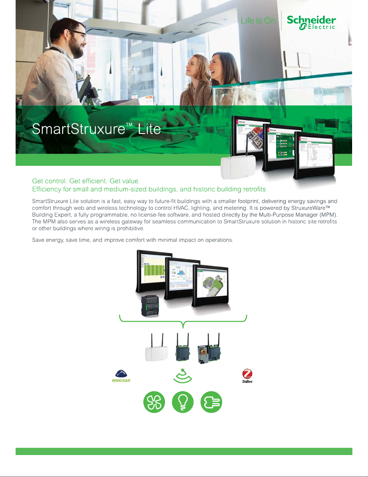
Schneider Electric SmartStruxure Solution
A6
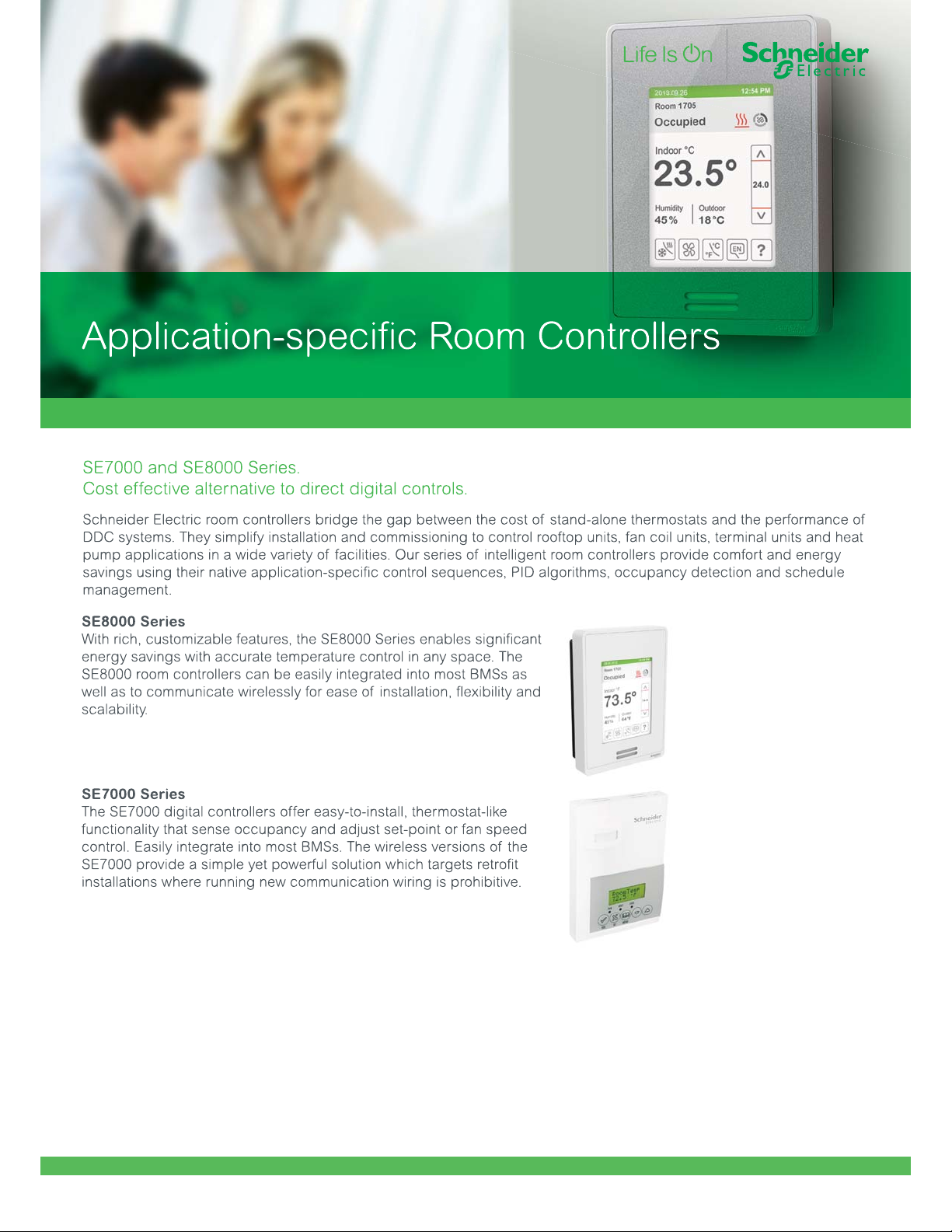
A7

Power Manager for SmartStruxure solution
Schneider Electric SmartStruxure Solution
A8

SmartStruxure solution engineering efficiency tools.
A9

AdaptiApps Custom End User
App Development Kit
Now, enhancing customer value is as simple as: Design, Deploy, Operate.
AdaptiApps is a custom end user app development kit that allows your customers to expand
building connectivity and control to any occupant, not only BMS professionals. AdaptiApps
puts seamless, aggregated data from multiple systems and services in the hands of building
occupants using a single, secure, aesthetic app accessible via their smar tphones or tablets.
AdaptiApps helps system integrators differentiate their business and
build custom
apartment complexes and healthcare facilities to ensure the best
possible experience for their customers.
er loyalty, while enabling managers of hotels,
Schneider Electric SmartStruxure Solution
A10
A10

Januar y 2017
©2016 Schn eider Elect ric. All Ri ghts Reser ved.
All tra demarks ar e owned by Sch neider Elec tric Indust ries SAS o r its affi liated comp anies.
PSG-SSS-A 4_Rev2
 Loading...