

Momentum
M1 Processor Adapter and
Option Adapter User Guide
870 USE 101 10 Version 2

Data, Illustrations, Alterations
Data and illustrations are not binding. We reserve the right to alter products in line with our policy of continuous product development.
If you have any sugge stions for impro vements or am endments or h ave found error s in this publi cation, please n otify us by e- mail at
techcomm@modicon.com.
Training
Schneider Electric Inc. offers suitable further training on the system.
Hotline
See addresses for Technical Support Centers at the end of this publication.
Trademarks
All terms used in this publication to denote Schneider Electric Inc. products are trademarks of Schneider Electric Inc.
All other terms use d in this publication to deno te products may be registere d trademarks and/or trademar ks of the corresponding
corporations.
Copyright
All rights are rese rved. No part of this document may be reproduced or transm itted in any form or by any me ans, electronic or
mechanical, including cop ying, processing or by online fil e tr ans fer , wi tho ut p erm ission i n writ in g fr om Schneider Electric Inc. You are
not authorized to translate this document into any other language.
© 2000 Schneider Electric Inc. All rights reserved.

Momentum
M1 Processor Adapter and
Option Adapter User Guide
870 USE 101 10 Version 2.0
November 2000

Document Set
Momentum I/O Bases User Guide
870 USE 002 00
Momentum Interbus Communication Adapter User Manual
870 USE 003 00
Momentum FI PIO Communication Adapter User Manual
870 USE 005 00
Momentum Ethernet Communciation Adapter User Guide
870 use 112 00
170 PNT Series Modbus Plus Communication Adapters for Momentum
User Guide
870 USE 103 00
170 NEF Series Modbus Plus Communication Adapters for Momentum
User Guide
870 USE 111 00

Preface
Preface
The data and illustrations found in this book are no t binding. We reserve the right
to modify our products i n line with ou r policy of cont inuous pr oduct deve lopment.
The information in this document is subject to chan ge without notice and should
not be construed as a commitment by Schneider Electric, Inc.
Schneider Electric, Inc assumes no responsibility for any errors that may appear in
this document. If you have any suggestions for improvements or amendments or
have found errors in this publication, please notify us through your distributor or
local Square D office.
No part of this document may be reproduced in any form or by any means,
electronic or mechanical, including photocopying, witho ut express written
permission of the Publisher, Schneider Electric, Inc.
CAUTION
All pertinent state, regional, and local safety regulations must be observed when
installing and using this product.
For reasons of safety and to assure compliance with documented system data, repairs to
components should be performed only by the manufacturer.
Failure to observe this precaution can result in injury or equipment damage.
MODSOFT
® is a registered trademark of Schneider Electric, Inc.
The following are trademarks of Schneider Electric, Inc.:
Modbus Modbus Plus Concept
Modicon 984
DIGITAL
® and DEC® are registered trademarks of Digital Equipment
Corporation.
IBM
® and IBM AT® are registered trademarks of International Business
Machines Corporation.
Microsoft
® and MS-DOS® are registered trademarks of Microsoft Corporation.
©Copyright 2000, Schneider Electric, Inc.
Printed in U.S.A.
870 USE 101 10 V.2 v

Preface
vi
870 USE 101 10 V.2

Contents
About This Book ..........................................................................................15
Revision History..............................................................................................15
Document Scope............................................................................................16
Validity Note ................................ ..... ...... ...... ..................................................16
Related Documentation ..................................................................................16
User Comments..............................................................................................16
Part I Getting Started........................................................................17
Chapter 1 Overview of Momentum M1 Processor Adapters ...............19
Section 1.1 Introducing the M1 Processor Adapters ........................................................20
Overview ........................................................................................................20
Front Panel illustration ...................................................................................21
Overview of Ports ..........................................................................................22
Memory and Performance Characteristics ....................................................24
Power Supply ................................................................................................27
Section 1.2 Features of Each Processor Adapter ............................................................28
Overview ........................................................................................................28
171 CCS 700 00 ............................................................................................29
171 CCS 700 10 ............................................................................................32
171 CCS 760 00 ............................................................................................35
171 CCC 760 10 ............................................................................................38
171 CCS 780 00 ............................................................................................41
171 CCC 780 10 ............................................................................................44
171 CCC 960 20 ............................................................................................47
171 CCC 960 30 ............................................................................................51
171 CCC 980 20 ............................................................................................56
171 CCC 980 30 ............................................................................................60
870 USE 101 10 V.2 vii

Contents
Chapter 2 Overview of Momentum Option Adapters ...........................65
Section 2.1 Introducing the Momentum Option Adapters .................................................66
Basic Features of Option Adapters ...............................................................66
Section 2.2 Serial Option Adapter ....................................................................................67
Overview .......................................................................................................67
Front Panel Components ..............................................................................68
Specifications ................................................................................................71
Section 2.3 Modbus Plus Option Adapter ........................................................................73
Overview .......................................................................................................73
Front Panel Components ..............................................................................74
Specifications ................................................................................................77
Section 2.4 Redundant Modbus Plus Option Adapter ......................................................79
Overview .......................................................................................................79
Front Panel Components ..............................................................................80
Specifications ................................................................................................84
Chapter 3 Assembling Momentum Components .......... .. .. .. .................87
Section 3.1 Assembling a CPU ........................................................................................88
Overview .......................................................................................................88
Assembling a Processor Adapter and I/O Base ............................................89
Disassembling a Processor Adapter from an I/O Base .................................92
Section 3.2 Assembling a CPU with an Option Adapter ...................................................94
Overview .......................................................................................................94
Assembling a Processor Adapter and an Option Adapter .............................95
Mounting the Assembled Adapters on the I/O Base .....................................98
Disassembling a Module with an Option Adapter ..........................................101
Section 3.3 Installing Batteries in an Option Adapter .......................................................105
Installation Guidelines ...................................................................................105
Section 3.4 Labeling the CPU ..........................................................................................107
Guidelines for Labeling the CPU ...................................................................107
Part II Communication Ports ...... .. ...................................................109
Chapter 4 Using the Modbus Ports .......................................................111
Section 4.1 Modbus Port 1 ...............................................................................................112
Overview .......................................................................................................112
Modbus Port 1 ...............................................................................................113
Cable Accessories for Modbus Port 1 ........................................................... 116
viii
870 USE 101 10 V.2

Contents
Pinouts for Modbus Port 1 .............................................................................117
Section 4.2 Modbus Port 2 ...............................................................................................119
Overview ........................................................................................................119
Modbus Port 2 ...................... ...... ...................................................................120
Four-Wire Cabling Schemes for Modbus RS485 Networks ..........................123
Two-Wire Cabling Schemes for Modbus RS485 Networks ...........................126
Cable for Modbus RS485 Networks .............................................................129
Connectors for Modbus RS485 Networks .....................................................132
Terminating Devices for Modbus RS485 Networks .......................................134
Pinouts for Modbus RS485 Networks ............................................................135
Chapter 5 Using the Ethernet Port ........................................................141
Section 5.1 Ethernet Port .................................................................................................142
Ethernet Port .................................................................................................143
Network Design Considerations ....................................................................144
Security ..........................................................................................................146
Cabling Schemes ..........................................................................................147
Pinouts ...........................................................................................................148
Assigning Ethernet Address Parameters .......................................................149
Using BOOTP Lite to Assign Address Parameters .......................................152
Reading Ethernet Network Statistics .............................................................153
Description .....................................................................................................154
Section 5.2 Establishing a Connection with an Ethernet Module .....................................158
Establishing a Connection with an Ethernet Module .....................................159
Section 5.3 Accessing Embedded Web Pages ................................................................162
Accessing the Web Utility Home Page ..........................................................163
Section 5.4 171 CCC 960 30 AND 171 CCC 980 30 Web Pages ....................................164
Momentum M1E Web Pages .........................................................................165
Momentum M1E Indicators ............................................................................170
Chapter 6 Using the I/OBus Port ...........................................................171
I/O Bus Port ...................................................................................................172
How I/OBus Works ........................................................................................173
Network Status Indication in the M1 Ethernet Module ...................................174
Guidelines for I/OBus Networks ....................................................................175
Cable Accessories .........................................................................................177
Pinouts ...........................................................................................................179
Chapter 7 Using the Modbus Plus Ports ...............................................181
Modbus Plus Features for Momentum ..........................................................182
Two Types of Modbus Plus Networks ...........................................................183
Standard Cabling Schemes ...........................................................................185
Cluster Mode Cabling Schemes ....................................................................187
870 USE 101 10 V.2 ix

Contents
Cable Accessories for Modbus Plus Networks ..............................................191
Pinouts and Wiring Illustrations for Modbus Plus Networks ..........................194
Modbus Plus Addresses ................................................................................198
Peer Cop .......................................................................................................200
Part III Modsoft ...................................................................................203
Chapter 8 Configuring an M1 CPU with Modsoft .................................205
Section 8.1 Configuring the Processor Adapter ...............................................................206
Overview .......................................................................................................206
Selecting an M1 Processor Adapter ..............................................................207
Specifying an M1 Processor Type .................................................................210
Default Configuration Parameters ..................................... ............................212
Changing the Range of Discrete and Register References ..........................215
Changing the Size of Your Application Logic Space .....................................217
Changing the Number of Segments ..............................................................218
Changing the Size of the I/O Map .................................................................220
Establishing Configuration Extension Memory ..............................................222
Section 8.2 Configuring Option Adapter Features ............................................................223
Overview .......................................................................................................223
Reserving and Monitoring a Battery Coil .......................................................224
Setting up the Time-of-Day Clock .................................................................226
Setting the Time ............................................................................................228
Reading the Time-of-Day Clock ....................................................................231
Section 8.3 Modifying Communication Port Parameters ..................................................232
Overview .......................................................................................................232
Accessing the Port Editor Screen ................................. ..... ...... ......................233
Parameters Which Should Not Be Changed .................................................234
Changing the Mode and Data Bits ................................................................235
Changing Parity .............................................................................................237
Changing the Baud Rate ...............................................................................238
Changing the Modbus Address .....................................................................239
Changing the Delay .......................................................................................240
Changing the Protocol on Modbus Port 2 .....................................................241
Section 8.4 I/O Mapping the Local I/O Points ..................................................................242
Accessing and Editing the I/O Map ...............................................................242
Chapter 9 I/O Mapping an I/OBus Network with Modsoft .................... 247
Supporting an I/O Map for an I/OBus Network ..............................................248
Accessing an I/O Map Screen for an I/OBus Network ..................................250
Editing the I/OBus I/O Map ............................................................................252
x
870 USE 101 10 V.2

Contents
Chapter 10 Configuring a Modbus Plus Network in Modsoft
with Peer Cop ....... ..................................................................257
Section 10.1 Getting Started ..............................................................................................258
Overview ........................................................................................................258
Accessing the Peer Cop Configuration Extension Screen ............................259
The Default Peer Cop Screen .......................................................................261
Section 10.2 Using Modbus Plus to Handle I/O .................................................................263
Overview ........................................................................................................263
Devices on the Network .......................................... ...... .................................264
Defining the Link and Accessing a Node .......................................................265
Confirming the Peer Cop Summary Information ............................................268
Specifying References for Input Data ................................................. ...... .....272
Accessing the Remaining Devices ................................................................276
Completing the I/O Device Configurati on in Peer Cop ..................................278
Section 10.3 Passing Supervisory Data over Modbus Plus ...............................................281
Overview ........................................................................................................281
Devices on the Network .......................................... ...... .................................282
Configuring a Node to Exchange Data ..........................................................283
Confirming the Peer Cop Summary Information ............................................286
Specifying References for Input and Output Data .........................................287
Defining the References for the Next Node ...................................................292
Defining References for the Supervisory Computer ......................................297
Completing the Configuration ........................................................................302
Chapter 11 Saving to Flash in Modsoft ...................................................303
Preparing to Save to Flash ............................................................................304
Saving to Flash ..............................................................................................305
Part IV Concept ..................................................................................307
Chapter 12 Configuring an M1 CPU with Concept .................................309
Section 12.1 Configuring the Processor Adapter ...............................................................310
Overview ........................................................................................................310
Selecting an M1 Processor Adapter ..............................................................311
Default Configuration Parameters .................................................................315
Changing the Range of Discrete and Register References ...........................318
Changing the Size of the Full Logic Area ......................................................320
Understanding the Number of Segments ......................................................321
Changing the Size of the I/O Map .................................................................322
Establishing Configuration Extension Memory for Peer Cop .........................324
Section 12.2 Configuring Option Adapter Features ............................................................327
870 USE 101 10 V.2 xi

Contents
Overview .......................................................................................................327
Reserving and Monitoring a Battery Coil .......................................................328
Setting up the Time-of-Day Clock .................................................................331
Setting the Time ............................................................................................334
Reading the Time-of-Day Clock ....................................................................335
Section 12.3 Modifying Modbus Port Parameters ..............................................................336
Overview .......................................................................................................336
Accessing the Modbus Port Settings Dialog Box ..........................................337
Changing the Baud Rate ...............................................................................338
Changing Mode and Data Bits ......................................................................339
Stop Bit Should Not Be Changed ..................................................................340
Changing Parity .............................................................................................340
Changing the Delay .......................................................................................341
Changing the Modbus Address .....................................................................342
Changing the Protocol on Modbus Port 2 .....................................................343
Section 12.4 Configuring Ethernet Address Parameters and I/O Scanning .......................344
Overview .......................................................................................................344
Accessing the Ethernet / I/O Scanner Screen ...............................................345
Ethernet Configuration Options .....................................................................347
Setting Ethernet Address Parameters ...........................................................348
Configuring I/O ..............................................................................................350
Completing the I/O Configuration ..................................................................354
Section 12.5 I/O Mapping the Local I/O Points ..................................................................357
Accessing and Editing the I/O Map ...............................................................357
Chapter 13 I/O Mapping an I/OBus Network with Concept ...................361
Supporting an I/O Map for an I/OBus Network ..............................................362
Accessing an I/O Map Screen for an I/OBus Network ..................................363
Editing the I/OBus I/O Map ............................................................................365
Chapter 14 Configuring a Modbus Plus Network in Concept
with Peer Cop .. ... ....................................................................369
Section 14.1 Getting Started ..............................................................................................370
Overview .......................................................................................................370
Accessing the Peer Cop Dialog Box ....................................... ..... ...... ...... .....371
Adjusting the Amount of Extension Memory .................................................373
Other Default Settings in the Peer Cop Dialog Box .......................................374
Section 14.2 Using Modbus Plus to Handle I/O .................................................................376
Overview .......................................................................................................376
Devices on the Network ................................... ...... ...... ..... ...... ......................377
Changing the Peer Cop Summary Information .............................................378
Specifying References for Input Data ............................................................380
xii
870 USE 101 10 V.2

Contents
Specifying References for Output Data .........................................................384
Section 14.3 Passing Supervisory Data over Modbus Plus ...............................................387
Overview ........................................................................................................387
Devices on the Network .......................................... ...... .................................388
Specifying References for Input and Output Data .........................................389
Defining the References for the Next Node ...................................................393
Defining References for the Supervisory PLC ...............................................396
Chapter 15 Saving to Flash with Concept ..............................................399
Saving to Flash ..............................................................................................399
Part V Appendices .............................................................................403
Appendix A Ladder Logic Elements and Instructions .............. .. .. .. .. ......405
Standard Ladder Logic Elements ..................................................................406
DX Loadable Support ....................................................................................410
A Special STAT Instruction ............................................................................411
Appendix B Run LED Flash Patterns and Error Codes ...........................417
Index ............................................................................................................421
870 USE 101 10 V.2 xiii

Contents
xiv
870 USE 101 10 V.2

About This Book
Revision History This is version 2.0 of this manual, 870 USE 101 1x, which replaces 870 USE 101 0x.
The following information has been added or changed:
Version Change
1.0 Never released.
2.0 Addition of new Ethernet-capable processors.
The most recent version of this manual is available on our web site,
www.modicon.com.
870 USE 101 10 V.2 15

About This Book
About Book
Document Scope This manual contains complete information about the Momentum M1 Processor
Adapters, Option Adapters and Ethernet Adapters. It does not contain information
about Momentum I/O bases or Communication Adapters.
Validity Note This manual is valid for Modsoft 2.6.1 and Concept 2.2.
Related
You may find the following other manuals useful:
Documentation
Title Part Number
Momentum I/O Bases User Guide 870 USE 002 00
Momentum Modbus Plus PNT Series Communication
Adapters User Guide
Momentum Modbus Plus NEF Series Communication
Adapters User Guide
Quantum NOE 771 x0 Ethernet Modules User Guide 840 USE 116 00
FactoryCast User’s Guide For Quantum and Premium 890 USE 152 00
Momentum Interbus Communication Adapter User
Manual
Momentum Ethernet Communication Adapter User
Guide
870 USE 103 00
870 USE 111 00
870 USE 003 00
870 USE 112 00
User Comments We welcome your comments about this document. You can reach us by e-mail at
techcomm@modicon.com.
16
870 USE 101 10 V.2

Getting Started
At a Glance
Purpose This part describes the M1 Processor Adapters and Option Adapters and explains
how to assemble them.
In This Part This part contains the following chapters:
For Information On... See Chapter... On Page...
Overview of Momentum M1 Processor Adapters 1 19
Overview of Momentum Option Adapters 2 65
Assembling Momentum Components 3 87
870 USE 101 10 V.2 17

Getting Started
18
870 USE 101 10 V.2

Overview of Momentum M1
Processor Adapters
At a Glance
Purpose A Momentum M1 Processor Adapter can be snapped onto a Momentum I/O base
to create a central process ing uni t (CPU) that pr ovi de s pro gram m abl e lo gic co ntrol
to local and distributed I/O.
This chapter describe s the M1 Processor Adapters.
In This Chapter This chapter contains t he following sections:
For This Topic... See Section... On Page...
Introducing the M1 Processor Adapters 1 20
Features of Each Processor Adapter 2 28
870 USE 101 10 V.2 19

Overview of Momentum M1 Processor Adapters
Section 1.1
Introducing the M1 Processor Adapters
Overview
Purpose A Momentum M1 Processor Adapter stores and executes the application progra m,
controlling the local I/O points of its host I/O base and distributed I/O devices on a
common communication bus.
This section describes the front panel components, memory and performance
characteristics of M1 Processor Adapters.
In This Section This section contains the following topics:
For This Topic... See Page...
Front Panel illustration 21
Overview of Ports 22
Memory and Performance Characteristics 24
Power Supply 27
20
870 USE 101 10 V.2
Overview of Momentum M1 Processor Adapters
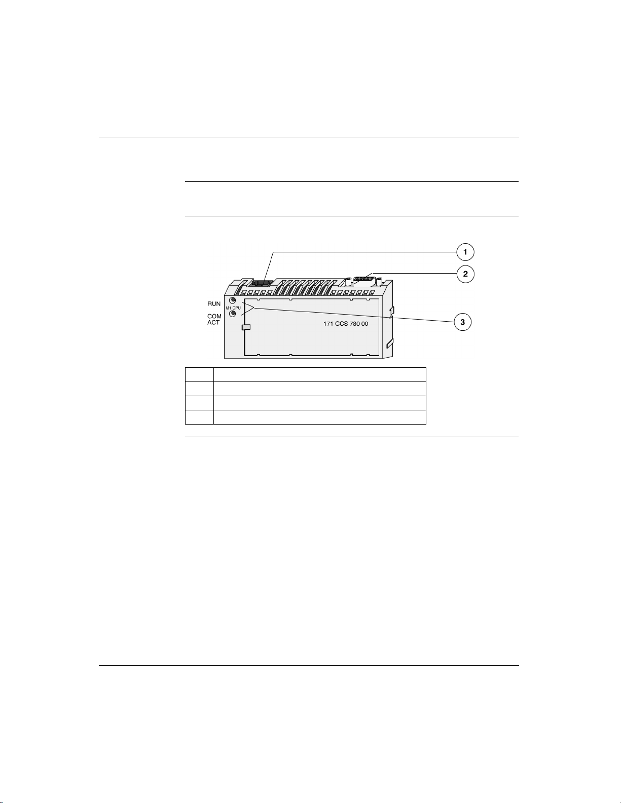
Front Panel illustration
Introduction This section provides an illustra tion of a typical M1 Processor Adapter.
Illustration A typical Processor Adapter is shown in the following illustration:
Label Description
1 Standard port connector
2 Optional second port connector
3 LED indicators
870 USE 101 10 V.2 21

Overview of Momentum M1 Processor Adapters
Overview of Ports
Introduction Each Processor Adapter is equipped with at least one Modbus or Ethernet port.
Some models also have a second port. The ports allow the Processor Adapter to
communicate wi th:
l Programming panels
l Network I/O points under its control
l Network supervisory computers
Ports Per
Processor
The following table indicates which ports are available with each Processor
Adapter:
Adapter
Port 1 Port 2
Processor
Adapter
171 CCS 700 00 x
171 CCS 700 10 x
171 CCS 760 00 x x
171 CCC 760 10 x x
171 CCS 780 00 x x
171 CCC 780 10 x x
171 CCC 960 20 x x
171 CCC 960 30 x x
171 CCC 980 20 x x
171 CCC 980 30 x x
Ethernet
Port
Modbus
RS-232
Modbus
RS-485
I/O Bus
Port
1
Schneider
Automation Inc.
171 CCS 780 00
1.
Port 1
Port 2
2.
2
Ethernet Port The Ethernet port is a standard, twisted pair, Ethernet 10BASE-T port which can
communicate with programming panels, other M1 Processor Adapters with
Ethernet ports, an d w it h o t her Ethe rnet products. This port has an RJ45 co nne ct or,
with an industry standard pinout.
Modbus Port 1 Modbus Port 1 is a general-purpose asynchronous serial port with dedicated
RS232 slave functionality. This port has an RJ45 connector.
Continued on next page
22
870 USE 101 10 V.2

Overview of Momentum M1 Processor Adapters
Overview of Ports, Continued
Modbus Port 2 Modbus Port 2 is a general-purpose asynchronous serial port with dedicated
RS485 slave functionality. This port has a 9-pin D connector.
I/OBus Port The I/OBus port is used to c ont rol and communicate w i th ot her n etw o rk (non-local)
I/O modules under the control of the CPU. This port has a 9-pin D connector.
870 USE 101 10 V.2 23

Overview of Momentum M1 Processor Adapters
Memory and Performance Characteristics
Introduction Processor Adapters are equipped with internal memory and Flash RAM. This
section explains those two types of memory and describes the memory size and
performance characteristics of each Processor Adapter.
Internal Memory Internal memory includes user memory and state RAM:
l User memory contains the control logic program and such system overhead as
the Processor Adapter configuration, I/O mapping, checksum and system
diagnostics.
l State RAM is the area in memory where all the input and output references for
program and control operations are defined and returned.
The user may change the way internal memory is allocated by adjusting
parameters for user memory and state RAM.
Flash RAM Flash RAM contains the executive firmware, which is the operating system for the
PLC. It also contains a firmware kernel, which cannot be changed. The kernel is a
small portion of memory that recognizes acceptable executive firmware packages
and allows them to be downloaded to the Processor Adapter.
24
Space is also provided in Flash so that a copy of the user program and state RAM
values can be stored. This ba ck-up cap abilit y is p articu larly us eful in c onfigu rations
where no battery is used (i.e., a Processor Adapter without an Option Adapter).
When the module is successfully communicating with other devices, if a ring
adapter with battery back up is not present, it is recommended that you stop the
processor and save the user program to Flash. This will save the processor’s ARP
cache and enable it to “remember” this information if power is lost or removed.
This procedure should also be followed whenever:
l A new or substitute device is installed on the network;
l The IP address of a network device has been changed.
Note: Some process ors run bo th IEC an d L add er L ogic and some run only IEC.
See table following.
Continued on next page
870 USE 101 10 V.2

Overview of Momentum M1 Processor Adapters
Memory and Performance Characteristics, Continued
Memory Size and
Clock Speed
The memory size and clock speed of each processor are described in the table
below:
Processor 984LL Flash RAM Clock Speed 984LL
Program
Memory
171 CCS 700 00 64K bytes 256K bytes 20MHz 2.4k 171 CCS 700 10 64K bytes 256K bytes 32MHz 2.4k 171 CCS 760 00 256K bytes 256K bytes 20MHz 12k 160k
171 CCC 760 10 512K bytes 512K bytes 32MHz 18k 240k
171 CCS 780 00 64K bytes 256K bytes 20MHz 2.4k 171 CCC 780 10 512K bytes 512K bytes 32MHz 18k 240k
171 CCC 960 20 544K bytes 512K bytes 50 MHz 18k 171 CCC 960 30 544K bytes 1 megabyte 50 MHz 18k 200k
171 CCC 980 20 544K bytes 512K bytes 50 MHz 18k 171 CCC 980 30 544K bytes 1 megabyte 50 MHz 18k 200k
* In a default configuration. The amount of user memory may be increased or decreased by
adjusting other parameters.
IEC
Program
Memory
870 USE 101 10 V.2 25

Overview of Momentum M1 Processor Adapters
Memory and Performance Characteristics, Continued
Input and Output
References
Processor Adapter 984LL Executive IEC Executive
171 CCS 700 00 2048 2048*
171 CCS 700 10 2048 2048*
171 CCS 760 00 4096 2048* 4096 2048 0
171 CCC 760 10 26048 8192 0
171 CCS 780 00 2048
171 CCC 780 10 26048 8192 0x references
171 CCC 960 20 26048 8192 0
171 CCC 960 30 26048 8192 0
171 CCC 980 20 26048 8192 0
171 CCC 980 30 26048 8192 0
*This total may include any combination of 0
The number of registers (for 3x and 4x references) and discretes (for 0x and 1x
references) supported by each processor are described in the table below:
Registers Discretes Registers Discretes
2048 1
8192 1
2048
8192 1
8192 1
8192 1
8192 1
8192 1
x
references
x
references
*
x
references
x
references
x
references
x
references
x
references
x
references
x
references
x
references
x
references
x
and 1x references.
26048 8192 0
8192 1
26048 8192 0
8192 1
11,200 4096 0
4096 1
11,200 4096 0
4096 1
x
references
x
references
x
references
x
references
x
references
x
references
x
references
x
references
x
references
x
references
26
870 USE 101 10 V.2

Power Supply
Overview of Momentum M1 Processor Adapters
Supplied by
Base
A Processor Adapter requires 5 V, which is supplied by its I/O base.
Note: For information about the 171 CPS 111 00 TIO Power Supply Module,
refer to 870 Use 002 00 V. 2
Momentum I/O Base User Guide
870 USE 101 10 V.2 27

Overview of Momentum M1 Processor Adapters
Section 1.2
Features of Each Processor Adapter
Overview
Purpose This section provides a photograph, description of key features and LEDs, and
specifications for each Processor Adapter.
In This Section This section contains the following topics.
For This Topic... See Page...
171 CCS 700 00 29
171 CCS 700 10 32
171 CCS 760 00 35
171 CCC 760 10 38
171 CCS 780 00 41
171 CCC 780 10 44
171 CCC 960 20 47
171 CCC 960 30 51
171 CCC 980 20 56
171 CCC 980 30 60
28
870 USE 101 10 V.2
Overview of Momentum M1 Processor Adapters
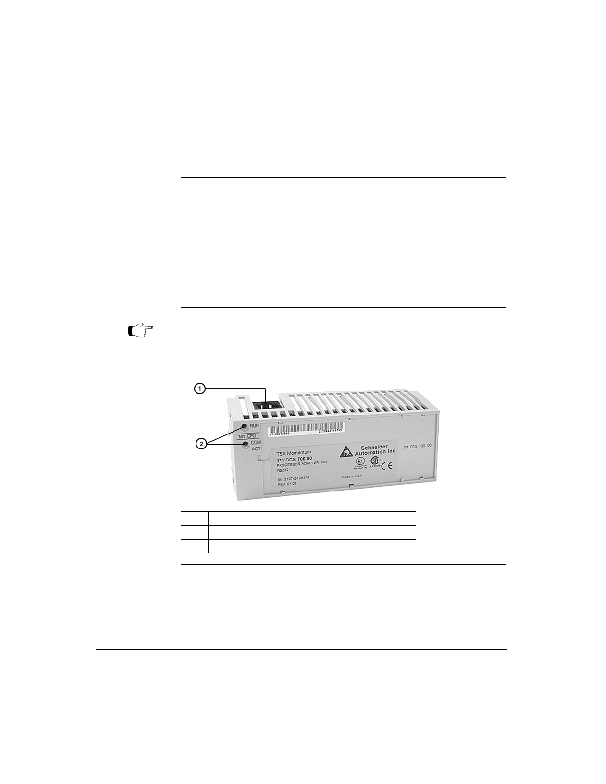
171 CCS 700 00
Overview This section describes the 171 CCS 700 00 Processor Adapter, including key
features, an illustration and specifications.
Key Features The key features of this Processor Adapter are:
l Modbus Port 1
l 64K bytes of internal memory
l 20 MHz clock speed
Note: The Modbus port connector looks like a Ethernet port connector. Do not
attempt to use an Modbus adapter as an Ethernet unit. Do not attempt to
place an Ethernet connector in a Modbus connector.
Illustration The connector and LED indicators are shown in the following illustration:
Label Description
1 Modbus Port 1 connector
2 LED indicators
Continued on next page
870 USE 101 10 V.2 29

Overview of Momentum M1 Processor Adapters
171 CCS 700 00, Continued
LED Indicators Th is Proc essor Adapter has two LED indicators, RUN and COM ACT. Their
functions are described in the table below:
LED Status Function
Start up Both Single flash. Indicates good health.
RUN Green On continuously when the CPU has received power and is
Off CPU is not powered up or is not solving logic.
COM ACT Green May be on continuously or blinking. Indicates activity on
Off No activity on Modbus port 1.
Specifications The following table contains specifications for the 171 CCS 700 00 Momentum M1
Processor Adapter:
Memory
Internal Memory 64K bytes
User Memory 2.4K words
Flash RAM 256K bytes
Clock Speed 20 MHz
Input and Output References
Registers 204 8
Discretes 2048 (any combination of 0
I/O Servicing
Local I/O Services all the points on any host Momentum I/O base
Watchdog timeout 419 ms
Logic solve time 0.25 ms/k ladder logic instructions
solving logic.
Flashes an error pattern if the CPU is in kernel mode.
Run LED Flash Patterns and Error Codes
(See
Modbus port 1.
x
and 1x references)
on page 417)
30
Continued on next page
870 USE 101 10 V.2

171 CCS 700 00, Continued
Overview of Momentum M1 Processor Adapters
Specifications,
Continued
Mechanical
Weight 42.5 g (1.5 oz.)
Dimensions (HxDxW) 25.9x61.02x125mm
Material (Enclosures/
bezels)
Operating Conditions
Temperature 0 ... 60 degrees C
Humidity 5 ... 95% (noncondensing)
Chemical interactions Enclosures and bezels are made of Lexan,
Altitude, full operation 2000m (6500ft)
Vibration 10 ... 57Hz @ 0.075mm displacement amplitude
Shock +/-15g peak, 11ms, half sine wave
RFI Susceptibility/
immunity
Storage Conditions
Temperature -40...+85 degrees C
Humidity 5 ... 95% (noncondensing)
Safety Parameters
Degree of protection Unintentional access (UL 508 Type 1, NEMA250 Type 1,
Di-electric strength RS232 is non-isolated from logic common
Agency Approvals
(1.01 x 2.37 x 4.86 in)
Lexan
a polycarbonate that can be damaged by strong
alkaline solutions
57...150Hz @ 1g
Ref. IEC 68-2-6 FC
Ref. IEC 68-2-27 EA
Meets CE mark requirements for open equipment.
Open equipment should be installed in an industrystandard enclosure, with access restricted to qualified
service personnel.
IP20 conforming to IEC529)
l
UL 508, CSA, CUL, CE
l
FM class1, div2
870 USE 101 10 V.2 31

Overview of Momentum M1 Processor Adapters
171 CCS 700 10
Overview This section describes the 171 CCS 700 10 Processor Adapter, including key
features, an illustration and specifications.
Key Features The key features of this Processor Adapter are:
l Modbus Port 1
l 64K bytes of internal memory
l 32 MHz clock speed
Note: The Modbus port connector looks like a Ethernet port connector. Do not
attempt to use an Modbus adapter as an Ethernet unit. Do not attempt to
place an Ethernet connector in a Modbus connector.
Illustration The connector and LED indicators are shown in the following illustration:
Label Description
1 Modbus Port 1 connector
2 LED indicators
Continued on next page
32
870 USE 101 10 V.2

Overview of Momentum M1 Processor Adapters
171 CCS 700 10, Continued
LED Indicators This Processor Adapter has two LED indicators, RUN and COM ACT. Their
functions are descri bed in the table below:
LED Status Function
Start up Both Single flash. Indicates good health.
RUN Green On continuously when the CPU has received power and is
Off CPU is not powered up or is not solving logic.
COM ACT Green May be on continuously or blinking. Indicates activity on
Off No activity on Modbus port 1.
Specifications The following table contains specifications for the 171 CCS 700 10 Momentum M1
Processor Adapter:
Memory
Internal Memory 64K bytes
User Memory 2.4K words
Flash RAM 256K bytes
Clock Speed 32 MHz
Input and Output References
Registers 2048
Discretes 2048 (any combination of 0
I/O Servicing
Local I/O Services all the points on any host Momentum I/O base
Watchdog timeout 262 ms
Logic solve time 0.16 ms/k ladder logic instructions
solving logic.
Flashes an error pattern if the CPU is in kernel mode.
Run LED Flash Patterns and Error Codes
(See
Modbus port 1.
x
and 1x references)
on page 417)
Continued on next page
870 USE 101 10 V.2 33

Overview of Momentum M1 Processor Adapters
171 CCS 700 10, Continued
Specifications,
Continued
Mechanical
Weight 42.5 g (1.5 oz.)
Dimensions (HxDxW) 25.9x61.02x125mm
Material (Enclosures/
bezels)
Operating Conditions
Temperature 0 ... 60 degrees C
Humidity 5 ... 95% (noncondensing)
Chemical interactions Enclosures and bezels are made of Lexan,
Altitude, full operation 2000m (6500ft)
Vibration 10 ... 57Hz @ 0.075mm displacement amplitude
Shock +/-15g peak, 11ms, half sine wave
RFI Susceptibility/
immunity
Storage Conditions
Temperature -40...+85 degrees C
Humidity 5 ... 95% (noncondensing)
Safety Parameters
Degree of protection Unintentional access (UL 508 Type 1, NEMA250 Type 1,
Di-electric strength RS232 is non-isolated from logic common
Agency Approvals
(1.01 x 2.37 x 4.86 in)
Lexan
a polycarbonate that can be damaged by strong
alkaline solutions
57...150Hz @ 1g
Ref. IEC 68-2-6 FC
Ref. IEC 68-2-27 EA
Meets CE mark requirements for open equipment.
Open equipment should be installed in an industrystandard enclosure, with access restricted to qualified
service personnel.
IP20 conforming to IEC529)
l
UL 508, CSA, CUL, CE
l
FM class1, div2
34
870 USE 101 10 V.2

Overview of Momentum M1 Processor Adapters
171 CCS 760 00
Overview This section describes the 171 CCS 760 00 Processor Adapter, including key
features, an illustration and specifications.
Key Features The key features of this Processor Adapter are:
l Modbus Port 1
l I/OBus port
l 256K bytes of internal memory
l 20 MHz clock speed
Note: The Modbus port connector looks like a Ethernet port connector. Do not
attempt to use an Modbus adapter as an Ethernet unit. Do not attempt to
place an Ethernet connector in a Modbus connector.
Illustration The connectors and LED indicators are shown in the following illustration:
Label Description
1 Modbus Port 1 connector
2 I/OBus port connector
3 LED indicators
Continued on next page
870 USE 101 10 V.2 35

Overview of Momentum M1 Processor Adapters
171 CCS 760 00, Continued
LED Indicators Th is Proc essor Adapter has two LED indicators, RUN and COM ACT. Their
functions are described in the table below:
LED Status Function
Start up Both Single flash. Indicates good health.
RUN Green On continuously when the CPU has received power and is
Off CPU is not powered up or is not solving logic.
COM ACT Green May be on continuously or blinking. Indicates activity on
Off No activity on Modbus port 1.
Specifications The following table contains specifications for the 171 CCS 760 00 Momentum M1
Processor Adapter:
Memory
Internal Memory 256K bytes
User Memory 12K words 984LL Exec
Flash RAM 256K bytes
Clock Speed 20 MHz
984LL Input and Output References
Registers 4096
Discretes 2048 (any combination of 0
IEC Input and Output References
Registers 4096
Discretes 2048 (any combination of 0
solving logic.
Flashes an error pattern if the CPU is in kernel mode.
Run LED Flash Patterns and Error Codes
(See
Modbus port 1.
160K words IEC Exec
x
and 1x references) 984LL
x
and 1x references)
on page 417)
36
Continued on next page
870 USE 101 10 V.2

171 CCS 760 00, Continued
Overview of Momentum M1 Processor Adapters
Specifications,
Continued
I/O Servicing
Local I/O Services all the points on any host Momentum I/O base
Watchdog timeout 419 ms
Logic solve time 0.25 ms/k ladder logic instructions
Mechanical
Weight 42.5 g (1.5 oz.)
Dimensions (HxDxW) 25.9x61.02x125mm
Material (Enclosures/
bezels)
Operating Conditions
Temperature 0 ... 60 degrees C
Humidity 5 ... 95% (noncondensing)
Chemical interactions Enclosures and bezels are made of Lexan,
Altitude, full operation 2000m (6500ft)
Vibration 10 ... 57Hz @ 0.075mm displacement amplitude
Shock +/-15g peak, 11ms, half sine wave
RFI Susceptibility/
immunity
Storage Conditions
Temperature -40 ... +85 degrees C
Humidity 5 ... 95% (noncondensing)
Safety Parameters
Degree of protection Unintentional access (UL 508 Type 1, NEMA250 Type 1,
Di-electric strength RS232 and I/OBus are non-isolated from logic common
Ground continuity 30 A test on the exposed metal connector
Agency Approvals
(1.01 x 2.37 x 4.86 in)
Lexan
a polycarbonate that can be damaged by strong
alkaline solutions
57...150Hz @ 1g
Ref. IEC 68-2-6 FC
Ref. IEC 68-2-27 EA
Meets CE mark requirements for open equipment.
Open equipment should be installed in an industrystandard enclosure, with access restricted to qualified
service personnel.
IP20 conforming to IEC529)
l
UL 508, CSA, CUL, CE
l
FM class1, div2
870 USE 101 10 V.2 37

Overview of Momentum M1 Processor Adapters
171 CCC 760 10
Overview This section describes the 171 CCC 760 10 Processor Adapter, including key
features, an illustration and specifications.
Key Features The key features of this Processor Adapter are:
l Modbus Port 1
l I/OBus port
l 512K bytes of internal memory
l 32 MHz clock speed
Note: The Modbus port connector looks like a Ethernet port connector. Do not
attempt to use an Modbus adapter as an Ethernet unit. Do not attempt to
place an Ethernet connector in a Modbus connector.
Illustration The connectors and LED indicators are shown in the following illustration:
Label Description
1 Modbus Port 1 connector
2 I/OBus port connector
3 LED indicators
Continued on next page
38
870 USE 101 10 V.2

Overview of Momentum M1 Processor Adapters
171 CCC 760 10, Continued
LED Indicators This Processor Adapter has two LED indicators, RUN and COM ACT. Their
functions are descri bed in the table below:
LED Status Function
Start up Both Single flash. Indicates good health.
RUN Green On continuously when the CPU has received power and is
Off CPU is not powered up or is not solving logic.
COM ACT Green May be on continuously or blinking. Indicates activity on
Off No activity on Modbus port 1.
Specifications The following table contains specifications for the 171 CCC 760 10 Momentum M1
Processor Adapter:
Memory
Internal Memory 512K bytes
User Memory 18K words 984LL Exec
Flash RAM 512K bytes
Clock Speed 32 MHz
984LL Input and Output References
Registers 26048
Discretes 8192 0
IEC Input and Output References
Registers 26048
Discretes 8192 0
solving logic.
Flashes an error pattern if the CPU is in kernel mode.
Run LED Flash Patterns and Error Codes
(See
Modbus port 1.
240K words IEC Exec
x
references
x
references
8192 1
x
references
x
references
8192 1
on page 417)
Continued on next page
870 USE 101 10 V.2 39

Overview of Momentum M1 Processor Adapters
171 CCC 760 10, Continued
Specifications,
Continued
I/O Servicing
Local I/O Services all the points on any host Momentum I/O base
Watchdog timeout 262 ms
Logic solve time 0.16 ms/k ladder logic instructions
Mechanical
Weight 42.5 g (1.5 oz.)
Dimensions (HxDxW) 25.9x61.02x125mm
Material (Enclosures/
bezels)
Operating Conditions
Temperature 0 ... 60 degrees C
Humidity 5 ... 95% (noncondensing)
Chemical interactions Enclosures and bezels are made of Lexan,
Altitude, full operation 2000m (6500ft)
Vibration 10 ... 57Hz @ 0.075mm displacement amplitude
Shock +/-15g peak, 11ms, half sine wave
RFI Susceptibility/
immunity
Storage Conditions
Temperature -40 ... +85 degrees C
Humidity 5 ... 95% (noncondensing)
Safety Parameters
Degree of protection Unintentional access (UL 508 Type 1, NEMA250 Type 1,
Di-electric strength RS232 and I/OBus are non-isolated from logic common
Ground continuity 30 A test on the exposed metal connector
Agency Approvals
(1.01 x 2.37 x 4.86 in)
Lexan
a polycarbonate that can be damaged by strong
alkaline solutions
57...150Hz @ 1g
Ref. IEC 68-2-6 FC
Ref. IEC 68-2-27 EA
Meets CE mark requirements for open equipment.
Open equipment should be installed in an industrystandard enclosure, with access restricted to qualified
service personnel.
IP20 conforming to IEC529)
l
UL 508, CSA, CUL, CE
l
FM class1, div2
40
870 USE 101 10 V.2

Overview of Momentum M1 Processor Adapters
171 CCS 780 00
Overview This section describes the 171 CCS 780 00 Processor Adapter, including key
features, an illustration and specifications.
Key Features The key features of this Processor Adapter are:
l Modbus Port 1
l Modbus Port 2
l 64K bytes of internal memory
l 20 MHz clock speed
Note: The Modbus port connector looks like a Ethernet port connector. Do not
attempt to use an Modbus adapter as an Ethernet unit. Do not attempt to
place an Ethernet connector in a Modbus connector.
Illustration The connectors and LED indicators are shown in the following illustration:
Label Description
1 Modbus Port 1 connector
2 Modbus Port 2 connector
3 LED indicators
Continued on next page
870 USE 101 10 V.2 41

Overview of Momentum M1 Processor Adapters
171 CCS 780 00, Continued
LED Indicators Th is Proc essor Adapter has two LED indicators, RUN and COM ACT. Their
functions are described in the table below:
LED Status Function
Start up Both Single flash. Indicates good health.
RUN Green On continuously when the CPU has received power and is
Off CPU is not powered up or is not solving logic.
COM ACT Green May be on continuously or blinking. Indicates activity on
Off No activity on Modbus port 1.
Specifications The following table contains specifications for the 171 CCS 780 00 Momentum M1
Processor Adapter:
Memory
Internal Memory 64K bytes
User Memory 2.4K words
Flash RAM 256K bytes
Clock Speed 20 MHz
984LL Input and Output References
Registers 204 8
Discretes 2048 (any combination of 0
IEC Input and Output References
Registers 2048
Discretes 2048 (any combination of 0
I/O Servicing
Local I/O Services all the points on any host Momentum I/O base
Watchdog timeout 419 ms
Logic solve time 0.25 ms/k ladder logic instructions
solving logic.
Flashes an error pattern if the CPU is in kernel mode.
Run LED Flash Patterns and Error Codes
(See
Modbus port 1.
x
and 1x references)
x
and 1x references)
on page 417)
42
Continued on next page
870 USE 101 10 V.2

171 CCS 780 00, Continued
Overview of Momentum M1 Processor Adapters
Specifications,
Continued
Mechanical
Weight 42.5 g (1.5 oz.)
Dimensions (HxDxW) 25.9x61.02x125mm
Material (Enclosures/
bezels)
Operating Conditions
Temperature 0 ... 60 degrees C
Humidity 5 ... 95% (noncondensing)
Chemical interactions Enclosures and bezels are made of Lexan,
Altitude, full operation 2000m (6500ft)
Vibration 10 ... 57Hz @ 0.075mm displacement amplitude
Shock +/-15g peak, 11ms, half sine wave
RFI Susceptibility/
immunity
Storage Conditions
Temperature -40 ... +85 degrees C
Humidity 5 ... 95% (noncondensing)
Safety Parameters
Degree of protection Unintentional access (UL 508 Type 1, NEMA250 Type 1,
Di-electric strength RS232 and RS485 are non-isolated from logic common
Ground continuity 30 A test on the exposed metal connector
Agency Approvals
(1.01 x 2.37 x 4.86 in)
Lexan
a polycarbonate that can be damaged by strong
alkaline solutions
57...150Hz @ 1g
Ref. IEC 68-2-6 FC
Ref. IEC 68-2-27 EA
Meets CE mark requirements for open equipment.
Open equipment should be installed in an industrystandard enclosure, with access restricted to qualified
service personnel.
IP20 conforming to IEC529)
l
UL 508, CSA, CUL, CE
l
FM class1, div2
870 USE 101 10 V.2 43

Overview of Momentum M1 Processor Adapters
171 CCC 780 10
Overview This section describes the 171 CCC 780 10 Processor Adapter, including key
features, an illustration and specifications.
Key Features The key features of this Processor Adapter are:
l Modbus Port 1
l Modbus Port 2
l 512K bytes of internal memory
l 32 MHz clock speed
Note: The Modbus port connector looks like a Ethernet port connector. Do not
attempt to use an Modbus adapter as an Ethernet unit. Do not attempt to
place an Ethernet connector in a Modbus connector.
Illustration The connectors and LED indicators are shown in the following illustration:
Label Description
1 Modbus Port 1 connector
2 Modbus Port 2 connector
3 LED indicators
Continued on next page
44
870 USE 101 10 V.2

Overview of Momentum M1 Processor Adapters
171 CCC 780 10, Continued
LED Indicators This Processor Adapter has two LED indicators, RUN and COM ACT. Their
functions are descri bed in the table below:
LED Status Function
Start up Both Single flash. Indicates good health.
RUN Green On continuously when the CPU has received power and is
Off CPU is not powered up or is not solving logic.
COM ACT Green May be on continuously or blinking. Indicates activity on
Off No activity on Modbus port 1.
Specifications The following table contains specifications for the 171 CCC 780 10 Momentum M1
Processor Adapter:
Memory
Internal Memory 512K bytes
User Memory 18K words 984LL Exec
Flash RAM 512K bytes
Clock Speed 32 MHz
984LL Input and Output References
Registers 26048
Discretes 8192 0
IEC Input and Output References
Registers 26048
Discretes 8192 0
I/O Servicing
Local I/O Services all the points on any host Momentum I/O base
Watchdog timeout 262 ms
Logic solve time 0.16 ms/k ladder logic instructions
solving logic.
Flashes an error pattern if the CPU is in kernel mode.
Run LED Flash Patterns and Error Codes
(See
Modbus port 1.
240k words IEC Exec
x
references
x
references
8192 1
x
references
x
references
8192 1
on page 417)
870 USE 101 10 V.2 45

Overview of Momentum M1 Processor Adapters
171 CCC 780 10, Continued
Specifications,
Continued
Mechanical
Weight 42.5 g (1.5 oz.)
Dimensions (HxDxW) 25.9x61.02x125mm
Material (Enclosures/
bezels)
Operating Conditions
Temperature 0 ... 60 degrees C
Humidity 5 ... 95% (noncondensing)
Chemical interactions Enclosures and bezels are made of Lexan,
Altitude, full operation 2000m (6500ft)
Vibration 10 ... 57Hz @ 0.075mm displacement amplitude
Shock +/-15g peak, 11ms, half sine wave
RFI Susceptibility/
immunity
Storage Conditions
Temperature -40 ... +85 degrees C
Humidity 5 ... 95% (noncondensing)
Safety Parameters
Degree of protection Unintentional access (UL 508 Type 1, NEMA250 Type 1,
Di-electric strength RS232 and RS485 are non-isolated from logic common
Ground continuity 30 A test on the exposed metal connector
Agency Approvals
(1.01 x 2.37 x 4.86 in)
Lexan
a polycarbonate that can be damaged by strong
alkaline solutions
57...150Hz @ 1g
Ref. IEC 68-2-6 FC
Ref. IEC 68-2-27 EA
Meets CE mark requirements for open equipment.
Open equipment should be installed in an industrystandard enclosure, with access restricted to qualified
service personnel.
IP20 conforming to IEC529)
l
UL 508, CSA, CUL, CE
l
FM class1, div2
46
870 USE 101 10 V.2

Overview of Momentum M1 Processor Adapters
171 CCC 960 20
Overview This section describes the 171 CCC 960 20 Processor Adapter, including key
features, a illustration and specifications.
Key Features The key features of this Processor Adapter are:
l Ethernet port
l I/OBus port
l 544K bytes of internal memory
l 50 MHz clock speed
Note: The Ethernet port connector looks like a Modbus port connector. Do not
attempt to use an Ethernet adapter as a Modbus unit. Do not attempt to
place a Modbus connector in an Ethernet connector.
Illustration The connectors and LED indicators are shown in the following illustration:
Label Description
1 Ethernet port connector
2 I/OBus port connector
3 LED indicators
Continued on next page
870 USE 101 10 V.2 47

Overview of Momentum M1 Processor Adapters
171 CCC 960 20, Continued
LED Indicators This Processor Adapter has three LED indicators, RUN, LAN ACT(IVE), and LAN
ST(ATUS). Their functions are described in the table below:
LED Indicato
r
Pattern
Start up Both Single flash. Indicates good health.
RUN Green On continuously when the CPU has received power and is
Off CPU is not powered up or is not solving logic.
LAN ACT Green May be on continuously or blinking. Indicates activity on
Off No activity on Ethernet port.
LAN ST Green On continuously during normal operation.
Off No valid MAC address.
Status
solving logic.
Flashes an error pattern if the CPU is in kernel mode. (See
LED Flash Patterns and Error Codes
Ethernet port.
Fast blink indicates normal Ethernet initialization at power-up.
3 flashes indicates no 10BASE-T link pulse detected. Check
cable and hub.
4 flashes indicates duplicate IP address detected.
5 flashes indicates no IP address available.
on page 417)
Run
Specifications The following table contains specifications for the 171 CCC 960 20 Momentum M1
Processor Adapter:
48
Memory
Internal Memory 544K bytes
User Memory 18K words
Flash RAM 512K bytes
Clock Speed 50 MHz
Continued on next page
870 USE 101 10 V.2

171 CCC 960 20, Continued
Overview of Momentum M1 Processor Adapters
Specifications,
Continued
Input and Output References
Registers 26048
Discretes 8192 0
I/O Servicing
Local I/O Services all the points on any host Momentum I/O base
Watchdog timeout 335 ms
Logic solve time See formula, following
Mechanical
Weight 42.5 g (1.5 oz.)
Dimensions (HxDxW) 25.9x61.02x125mm
Material (Enclosures/
bezels)
Operating Conditions
Temperature 0 ... 60 degrees C
Humidity 5 ... 95% (noncondensing)
Chemical interactions Enclosures and bezels are made of Lexan,
Altitude, full operation 2000m (6500ft)
Vibration 10 ... 57Hz @ 0.075mm displacement amplitude
Shock +/-15g peak, 11ms, half sine wave
RFI Susceptibility/
immunity
x
references
x
references
8192 1
(1.01 x 2.37 x 4.86 in)
Lexan
a polycarbonate that can be damaged by strong
alkaline solutions
57...150Hz @ 1g
Ref. IEC 68-2-6 FC
Ref. IEC 68-2-27 EA
Meets CE mark requirements for open equipment.
Open equipment should be installed in an industrystandard enclosure, with access restricted to qualified
service personnel.
Continued on next page
870 USE 101 10 V.2 49

Overview of Momentum M1 Processor Adapters
171 CCC 960 20, Continued
Specifications,
Continued
Scantime
Formula for
984LL Exec
Storage Conditions
Temperature -40 ... +85 degrees C
Humidity 5 ... 95% (noncondensing)
Safety Parameters
Degree of protection Unintentional access (UL 508 Type 1, NEMA250 Type 1,
IP20 conforming to IEC529)
Di-electric strength Ethernet is isolated from logic common 500 VDC
Ground continuity 30 A test on the exposed metal connector
Agency Approvals
l
UL 508, CSA, CUL, CE
l
FM class1, div2
The following formula applies to the M1E Processor Adapter with the 984LL exec.
Scan time = (0.25 msec/ethernet device + 0.002 msec/word) + 0.13 msec/K of
logic + 0.40 msec + MBPlustime
Note:
l
Modbus Plus communications will slow the M1E. If there is no MB+ ring card then
MBPlustime = 0.
l
If there is a MB+ ring card, then each scan will be extended 0.3 Msec
message
l
Modbus Messages will add from 1 to 2 msec per scan, depending on the length of the
message.
.
even if there is no
Note:
l
The formula above presumes that all MSTR blocks and all configured connections are
set to go as fast as possible. In this case the M1E will attempt to exchange data with
each device once per scan.
l
If several devices are configured to communicate on a timed basis that is substantially
larger than the scan time calculated, then the communications to those devices will be
spread out over several scans. See Example, below.
Example Y ou ha ve 50 EN T mo dul es con nec te d to a s ingle M1E with a configured time of 50
Msec each, a total of 4k user logic and n o MB+ c ard. The scan time for all modules
configured as fast as possible would be 12.5 Msec + 0.52 Msec + 0.40 Msec =
13.42 Msec. However, since the M1E will only communicate to 1/4 of the modules
(12.5 Msec/50 Msec = 1/4) on any given scan, the corrected average scan time
would be 1/4 x (12.5) + 0.52 + 0.40
≅ 4.1 Msec.
50
870 USE 101 10 V.2

Overview of Momentum M1 Processor Adapters
171 CCC 960 30
Overview This section describes the 171 CCC 960 30 Processor Adapter, including key
features, an illustration and specifications.
Note: The 171 CCC 960 30 units are shipped with the latest IEC exec installed.
Note: The 984LL exec used in the 171 CCC 960 30 will not operate in a
171 CCC 960 20
Key Features The key features of this Processor Adapter are:
l Ethernet port
l I/OBus port
l 544K bytes of internal memory
l 50 MHz clock speed
Note: The Ethernet port connector looks like a Modbus port connector. Do not
attempt to use an Ethernet adapter as a Modbus unit. Do not attempt to
place a Modbus connector in an Ethernet connector.
Continued on next page
870 USE 101 10 V.2 51

Overview of Momentum M1 Processor Adapters
171 CCC 960 30, Continued
Illustration The connectors and LED indicators are shown in the following illustration:
1
3
Label Description
1 Ethernet port connector
2 I/OBus port connector
3 LED indicators
2
52
870 USE 101 10 V.2

Overview of Momentum M1 Processor Adapters
171 CCC 960 30, Continued
LED Indicators This Processor Adapter has three LED indicators, RUN, LAN ACT(IVE), and LAN
ST(ATUS). Their functions are described in the ta ble below:
LED Indicator
Pattern
Start up Both Single flash. Indicates good health.
RUN Green On continuously when the CPU has received power and is
Off CPU is not powered up or is not solving logic.
LAN ACT Green May be on continuously or blinking. Indicates activity on
Off No activity on Ethernet port.
LAN ST Green On continuously during normal operation.
Off No valid MAC address.
Status
solving logic.
Flashes an error pattern if the CPU is in kernel mode. (See
LED Flash Patterns and Error Codes
Ethernet port.
Fast blink indicates normal Ethernet initialization at power-up.
3 flashes indicates no 10BASE-T link pulse detected. Check
cable and hub.
4 flashes indicates duplicate IP address detected.
5 flashes indicates no IP address available.
on page 417)
Run
Specifications The following table contains specifications for the 171 CCC 960 30 Momentum M1
Processor Adapter:
Memory
Internal Memory 544K bytes
User Memory 18K words 984LL Exec
200k words IEC Exec
Flash RAM 1 Megabyte
Clock Speed 50 MHz
Continued on next page
870 USE 101 10 V.2 53

Overview of Momentum M1 Processor Adapters
171 CCC 960 30, Continued
Specifications,
Continued
984LL Input and Output References
Registers 260 48
Discretes 8192 0
IEC Input and Output References
Registers 11200
Discretes 4096 0x references
I/O Servicing
Local I/O Services all the points on any host Momentum I/O base
Watchdog timeout 335 ms
Logic solve time See formula, following
Mechanical
Weight 42.5 g (1.5 oz.)
Dimensions (HxDxW) 25.9x61.02x125mm
Material (Enclosures/
bezels)
Operating Conditions
Temperature 0 ... 60 degrees C
Humidity 5 ... 95% (noncondensing)
Chemical interactions Enclosures and bezels are made of Lexan,
Altitude, full operation 2000m (6500ft)
Vibration 10 ... 57Hz @ 0.075mm displacement amplitude
Shock +/-15g peak, 11ms, half sine wave
RFI Susceptibility/
immunity
x
references
8192 1
x
references
4096 1x references
(1.01 x 2.37 x 4.86 in)
Lexan
a polycarbonate that can be damaged by strong
alkaline solutions
57...150Hz @ 1g
Ref. IEC 68-2-6 FC
Ref. IEC 68-2-27 EA
Meets CE mark requirements for open equipment.
Open equipment should be installed in an industry-
standard enclosure, with access restricted to qualified
service personnel.
54
Continued on next page
870 USE 101 10 V.2

171 CCC 960 30, Continued
Overview of Momentum M1 Processor Adapters
Specifications,
Continued
Scantime
Formula for
984LL Exec
Storage Conditions
Temperature -40 ... +85 degrees C
Humidity 5 ... 95% (noncondensing)
Safety Parameters
Degree of protection Unintentional access (UL 508 Type 1, NEMA250 Type 1,
IP20 conforming to IEC529)
Di-electric strength Ethernet is isolated from logic common 500 VDC
Ground continuity 30 A test on the exposed metal connector
Agency Approvals
l
UL 508, CSA, CUL, CE
l
FM class1, div2
The following formula applies to the M1E Processor Adapter with the 984LL exec.
Scan time = (0.25 msec/ethernet device + 0.002 msec/word) + 0.13 msec/K of
logic + 0.40 msec + MBPlustime
Note:
l
Modbus Plus communications will slow the M1E. If there is no MB+ ring card then
MBPlustime = 0.
l
If there is a MB+ ring card, then each scan will be extended 0.3 Msec
message
l
Modbus Messages will add from 1 to 2 msec per scan, depending on the length of the
message.
.
even if there is no
Note:
l
The formula above presumes that all MSTR blocks and all configured connections are
set to go as fast as possible. In this case the M1E will attempt to exchange data with
each device once per scan.
l
If several devices are configured to communicate on a timed basis that is substantially
larger than the scan time calculated, then the communications to those devices will be
spread out over several scans. See Example, below.
Example You have 50 ENT modules connected to a single M1E w ith a co nfig ure d tim e of 50
Msec each, a total of 4k user logic and n o MB+ c ard. The scan time for all modules
configured as fast as possible would be 12.5 Msec + 0.52 Msec + 0.40 Msec =
13.42 Msec. However, since the M1E will only communicate to 1/4 of the modules
(12.5 Msec/50 Msec = 1/4) on any given scan, the corrected average scan time
would be 1/4 x (12.5) + 0.52 + 0.40
≅ 4.1 Msec.
870 USE 101 10 V.2 55

Overview of Momentum M1 Processor Adapters
171 CCC 980 20
Overview This section describes the 171 CCC 980 20 Processor Adapter, including key
features, an illustration and specifications.
Key Features The key features of this Processor Adapter are:
l Ethernet port
l Modbus Port 2 / RS485 only
l 544K bytes of internal memory
l 50 MHz clock speed
Note: The Ethernet port connector looks like a Modbus port connector. Do not
attempt to use an Ethernet adapter as a Modbus unit. Do not attempt to
place a Modbus connector in an Ethernet connector.
Illustration The connectors and LED indicators are shown in the following illustration.
1
er
eid
n
ch
S
c.
In
n
o
i
at
m
o
t
u
A
m
u
t
en
m
o
M
X
S
T
3
Label Description
1 Ethernet port connector
2 Modbus Port 2 connector
3 LED indicators
Continued on next page
2
56
870 USE 101 10 V.2

Overview of Momentum M1 Processor Adapters
171 CCC 980 20, Continued
LED Indicators This Processor Adapter has three LED indicators, RUN, LAN ACT(IVE), and LAN
ST(ATUS). Their functions are described in the ta ble below:
LED Indicator
Pattern
Start up Both Single flash. Indicates good health.
RUN Green On continuously when the CPU has received power and is
Off CPU is not powered up or is not solving logic.
LAN ACT Green May be on continuously or blinking. Indicates activity on
Off No activity on Ethernet port.
LAN ST Green On continuously during normal operation.
Off No valid MAC address.
Status
solving logic.
Flashes an error pattern if the CPU is in kernel mode. (See
LED Flash Patterns and Error Codes
Ethernet port.
Fast blink indicates normal Ethernet initialization at power-up.
3 flashes indicates no 10BASE-T link pulse detected. Check
cable and hub.
4 flashes indicates duplicate IP address detected.
5 flashes indicates no IP address available.
on page 417)
Run
Specifications The following table contains specifications for the 171 CCC 980 20 Momentum M1
Processor Adapter:
Memory
Internal Memory 544K bytes
User Memory 18K words
Flash RAM 512K bytes
Clock Speed 50 MHz
Continued on next page
870 USE 101 10 V.2 57

Overview of Momentum M1 Processor Adapters
171 CCC 980 20, Continued
Specifications,
Continued
Input and Output References
Registers 260 48
Discretes 8192 0
I/O Servicing
Local I/O Services all the points on any host Momentum I/O base
Watchdog timeout 335 ms
Logic solve time See formula, following
Mechanical
Weight 42.5 g (1.5 oz.)
Dimensions (HxDxW) 25.9x61.02x125mm
Material (Enclosures/
bezels)
Operating Conditions
Temperature 0 ... 60 degrees C
Humidity 5 ... 95% (noncondensing)
Chemical interactions Enclosures and bezels are made of Lexan,
Altitude, full operation 2000m (6500ft)
Vibration 10 ... 57Hz @ 0.075mm displacement amplitude
Shock +/-15g peak, 11ms, half sine wave
RFI Susceptibility/
immunity
x
references
x
references
8192 1
(1.01 x 2.37 x 4.86 in)
Lexan
a polycarbonate that can be damaged by strong
alkaline solutions
57...150Hz @ 1g
Ref. IEC 68-2-6 FC
Ref. IEC 68-2-27 EA
Meets CE mark requirements for open equipment.
Open equipment should be installed in an industry-
standard enclosure, with access restricted to qualified
service personnel.
58
Continued on next page
870 USE 101 10 V.2

171 CCC 980 20, Continued
Overview of Momentum M1 Processor Adapters
Specifications,
Continued
Scantime
Formula for
984LL Exec
Storage Conditions
Temperature -40 ... +85 degrees C
Humidity 5 ... 95% (noncondensing)
Safety Parameters
Degree of protection Unintentional access (UL 508 Type 1, NEMA250 Type 1,
Di-electric strength Ethernet is isolated from logic common 500 VDC
Ground continuity 30 A test on the exposed metal connector
Agency Approvals
IP20 conforming to IEC529)
l
UL 508, CSA, CUL, CE
l
FM class1, div2
The following formula applies to the M1E Processor Adapter with the 984LL exec.
Scan time = (0.25 msec/ethernet device + 0.002 msec/word) + 0.13 msec/K of
logic + 0.40 msec + MBPlustime
Note:
l
Modbus Plus communications will slow the M1E. If there is no MB+ ring card then
MBPlustime = 0.
l
If there is a MB+ ring card, then each scan will be extended 0.3 Msec
message
l
Modbus Messages will add from 1 to 2 msec per scan, depending on the length of the
message.
.
even if there is no
Note:
l
The formula above presumes that all MSTR blocks and all configured connections are
set to go as fast as possible. In this case the M1E will attempt to exchange data with
each device once per scan.
l
If several devices are configured to communicate on a timed basis that is substantially
larger than the scan time calculated, then the communications to those devices will be
spread out over several scans. See Example, below.
Example You have 50 ENT modules connected to a single M1E w ith a co nfig ure d tim e of 50
Msec each, a total of 4k user logic and n o MB+ c ard. The scan time for all modules
configured as fast as possible would be 12.5 Msec + 0.52 Msec + 0.40 Msec =
13.42 Msec. However, since the M1E will only communicate to 1/4 of the modules
(12.5 Msec/50 Msec = 1/4) on any given scan, the corrected average scan time
would be 1/4 x (12.5) + 0.52 + 0.40
870 USE 101 10 V.2 59
≅ 4.1 Msec.

Overview of Momentum M1 Processor Adapters
171 CCC 980 30
Overview This section describes the 171 CCC 980 30 Processor Adapter, including key
features, an illustration and specifications.
Note: The 171 CCC 980 30 units are shipped with the latest IEC exec installed.
Note: The 984LL exec used in the 171 CCC 980 30 will not operate in a
171 CCC 980 20
Key Features The key features of this Processor Adapter are:
l Ethernet port
l Modbus Port 2 / RS485 only
l 544K bytes of internal memory
l 50 MHz clock speed
Note: The Ethernet port connector looks like a Modbus port connector. Do not
attempt to use an Ethernet adapter as a Modbus unit. Do not attempt to
place a Modbus connector in an Ethernet connector.
Continued on next page
60
870 USE 101 10 V.2

Overview of Momentum M1 Processor Adapters
171 CCC 980 30, Continued
Illustration The connectors and LED indicators are shown in the following illustration:
1
3
2
Label Description
1 Ethernet port connector
2 Modbus Port 2 connector
3 LED indicators
Continued on next page
870 USE 101 10 V.2 61

Overview of Momentum M1 Processor Adapters
171 CCC 980 30, Continued
LED Indicators This Processor Adapter has three LED indicators, RUN, LAN ACT(IVE), and LAN
ST(ATUS). Their functions are described in the table below:
LED Indicator
Pattern
Start up Both Single flash. Indicates good health.
RUN Green On continuously when the CPU has received power and is
Off CPU is not powered up or is not solving logic.
LAN ACT Green May be on continuously or blinking. Indicates activity on
Off No activity on Ethernet port.
LAN ST Green On continuously during normal operation.
Off No valid MAC address.
Status
solving logic.
Flashes an error pattern if the CPU is in kernel mode. (See
LED Flash Patterns and Error Codes
Ethernet port.
Fast blink indicates normal Ethernet initialization at power-up.
3 flashes indicates no 10BASE-T link pulse detected. Check
cable and hub.
4 flashes indicates duplicate IP address detected.
5 flashes indicates no IP address available.
on page 417)
Run
Specifications The following table co ntains specifications for the 171 CCC 980 30 Momentu m M1
Processor Adapter:
62
Memory
Internal Memory 544K bytes
User Memory 18K words 984LL Exec
200k words IEC Exec
Flash RAM 1 Megabyte
Clock Speed 50 MHz
Continued on next page
870 USE 101 10 V.2

171 CCC 980 30, Continued
Specifications,
Continued
984LL Input and Output References
Registers 26048
Discretes 8192 0
IEC Input and Output References
Registers 11200
Discretes 4096 0
I/O Servicing
Local I/O Services all the points on any host Momentum I/O base
Watchdog timeout 335 ms
Logic solve time See formula, following
Mechanical
Weight 42.5 g (1.5 oz.)
Dimensions (HxDxW) 25.9x61.02x125mm
Material (Enclosures/
bezels)
Operating Conditions
Temperature 0 ... 60 degrees C
Humidity 5 ... 95% (noncondensing)
Chemical interactions Enclosures and bezels are made of Lexan,
Altitude, full operation 2000m (6500ft)
Vibration 10 ... 57Hz @ 0.075mm displacement amplitude
Shock +/-15g peak, 11ms, half sine wave
RFI Susceptibility/
immunity
Overview of Momentum M1 Processor Adapters
x
references
8192 1
x
references
x
references
4096 1
x
references
(1.01 x 2.37 x 4.86 in)
Lexan
a polycarbonate that can be damaged by strong
alkaline solutions
57...150Hz @ 1g
Ref. IEC 68-2-6 FC
Ref. IEC 68-2-27 EA
Meets CE mark requirements for open equipment.
Open equipment should be installed in an industry-
standard enclosure, with access restricted to qualified
service personnel.
Continued on next page
870 USE 101 10 V.2 63

Overview of Momentum M1 Processor Adapters
171 CCC 980 30, Continued
Specifications,
Continued
Scantime
Formula for
984LL Exec
Storage Conditions
Temperature -40 ... +85 degrees C
Humidity 5 ... 95% (noncondensing)
Safety Parameters
Degree of protection Unintentional access (UL 508 Type 1, NEMA250 Type 1,
Di-electric strength Ethernet is isolated from logic common 500 VDC
Ground continuity 30 A test on the exposed metal connector
Agency Approvals
IP20 conforming to IEC529)
l
UL 508, CSA, CUL, CE
l
FM class1, div2
The following formula applies to the M1E Processor Adapter with the 984LL exec.
Scan time = (0.25 msec/ethernet device + 0.002 msec/word) + 0.13 msec/K of
logic + 0.40 msec + MBPlustime
Note:
l
Modbus Plus communications will slow the M1E. If there is no MB+ ring card then
MBPlustime = 0.
l
If there is a MB+ ring card, then each scan will be extended 0.3 Msec
message
l
Modbus Messages will add from 1 to 2 msec per scan, depending on the length of the
message.
.
even if there is no
Note:
l
The formula above presumes that all MSTR blocks and all configured connections are
set to go as fast as possible. In this case the M1E will attempt to exchange data with
each device once per scan.
l
If several devices are configured to communicate on a timed basis that is substantially
larger than the scan time calculated, then the communications to those devices will be
spread out over several scans. See Example, below.
Example Y ou ha ve 50 EN T mo dul es con nec te d to a s ingle M1E with a configured time of 50
Msec each, a total of 4k user logic and n o MB+ c ard. The scan time for all modules
configured as fast as possible would be 12.5 Msec + 0.52 Msec + 0.40 Msec =
13.42 Msec. However, since the M1E will only communicate to 1/4 of the modules
(12.5 Msec/50 Msec = 1/4) on any given scan, the corrected average scan time
would be 1/4 x (12.5) + 0.52 + 0.40
64
≅ 4.1 Msec.
870 USE 101 10 V.2

Overview of Momentum Option
Adapters
At a Glance
Purpose An Option Adapter can be inserted between the Processor Adapter and the I/O
base to provide:
l A battery backup for the CPU
l A time-of-day clock
l Extra communication ports
This chapter describes the three types of Momentum Option Adapters.
In This Chapter This chapter contains t he following sections:
For This Topic... See Section... On Page...
Introducing the Momentum Option Adapters 1 66
Serial Option Adapter 2 6 7
Modbus Plus Option Adapter 3 73
Redundant Modbus Plus Option Adapter 4 79
870 USE 101 10 V.2 65

Option Adapters
Section 2.1
Introducing the Momentum Option Adapters
Basic Features of Option Adapters
Introduction This section describes the basic features of all Option Adapters:
l Batteries
l A time-of-day (TOD) clock
l Communication port(s)
Batteries The batteries back up the CPU’s user program and state RAM.
Time-of-Day
Clock
Communication
Ports
66
The time-of-day clock allows you to use the date and time as an element in your
user program.
The three Momentum Option Adapters are distinguished by the communications
ports they offer, as shown in the table below:
Option Adapter Communication Port(s)
172 JNN 210 32 Software-selectable RS232/RS485 serial port
172 PNN 210 22 One Modbus Plus port
172 PNN 260 22 Two Modbus Plus ports for a redundant (back-up) cable run
870 USE 101 10 V.2

Option Adapters
Section 2.2
Serial Option Adapter
Overview
Purpose This section describes the 172 JNN 210 32 Serial Option Adapter, including the
front panel components and specifications.
In This Section This section includes the following t opics:
For This Topic... See Page...
Front Panel Components 68
Specifications 71
870 USE 101 10 V.2 67

Option Adapters
Front Panel Components
Overview The front panel includes:
l An LED indicator
l Battery compartment
l Modbus Port 2 connector
Illustration The illustration below shows the location of LED indicator, the battery compartment,
and the Modbus Port 2 connector.
68
Label Description
1 LED indicator
2 Battery compartment door
3 Modbus Port 2 connector
Continued on next page
870 USE 101 10 V.2

Option Adapters
Front Panel Components, Continued
LED Indicator This Option Adapt er has on e LED in dicat or, the Com Act indicator . It s fun ction s are
described in the table below.
LED Status Function
COM ACT Green May be on steadily or blinking. Indicates activit y on the RS232/
Off No activity on the RS232/RS485 serial port.
Modbus Port 2 Modbus Port 2 is a general-purpose asynchronous serial port with user-selectable
RS232/RS485 slave functionality. The choice between RS232 and RS485 is made
in the software.
RS485 serial port.
Auto-Logout
Feature On
Modbus Port 2
Note: When this Option Adapter is assembled with a 171 CCS 780 00
Processor Adapter or a 171 CCC 780 10 Processor Adapter (with built-in
Modbus Port 2), the Modbus Port 2 on the Option Adapter is electrically
disabled. The TOD clock and the battery backup on the Option Adapter
remain functional.
If the RS232 port is chosen, auto-logout is supported. If a programming panel is
logged into the CPU via the serial port and its cable gets disconnected, the
Processor Adapter automatically logs out the port. This auto-logout feature is
designed to prevent a lock-up situation that could prevent other host stations from
logging in on other ports.
Auto-logout is not available for any RS485 port, including the RS485 option on the
Serial Option Adapter. The user must log out of the processor using the
programming software.
Continued on next page
870 USE 101 10 V.2 69

Option Adapters
Front Panel Components, Continued
Pinouts for
Modbus Port 2
The 172 JNN 210 32 Serial Option Adapter uses the following pinouts:
Pin For RS232 For RS485
1 DTR RXD 2 DSR RXD +
3TXD TXD +
4RXD
5 signal common signal common
6RTS TXD 7CTS
8 cable shield cable shield
70
870 USE 101 10 V.2

Option Adapters
Specifications
Specifications This section provides the specifications for the 172 JNN 210 32 Momentum Serial
Option Adapter:
Mechanical
Weight 85.05 g (3 oz.)
Dimensions (HxDxW) 58.3 (on battery side) x 60.6 x 143.1mm
(2.27 x 2.36 x 5.57 in)
Material (Enclosures/bezels) Lexan
Time-of-Day Clock
Accuracy +/- 13 s/day
Batteries
Type AAA alkaline, two required
Service life < 30 days from the time a battery-low indication is received
Shelf life In excess of 5 yr. @ room temperature
Operating Conditions
Temperature 0 ... 60 degrees C
Humidity 5 ... 95% (noncondensing)
Chemical interactions Enclosures and bezels are made of Lexan,
Altitude, full operation 2000m (6500ft)
Vibration 10 ... 57Hz @ 0.075mm displacement amplitude
Shock +/-15g peak, 11ms, half sine wave
two included with Option Adapter (in separate package)
to actual battery failure @ 40degrees C maximum ambient
temperature with the system continuously powered down.
a polycarbonate that can be damaged by strong
alkaline solutions
57...150Hz @ 1g
Ref. IEC 68-2-6 FC
Ref. IEC 68-2-27 EA
Continued on next page
870 USE 101 10 V.2 71

Option Adapters
Specifications, Continued
Specifications,
Continued
RFI Susceptibility/ immunity Meets CE mark requirements for open equipment.
Storage Conditions
Temperature -40...+85 degrees C
Humidity 5 ... 95% (noncondensing)
Safety Parameters
Degree of protection Unintentional access (UL 508 Type 1, NEMA250 Type 1,
Di-electric strength RS232/485 is non-isolated from logic common
Agency Approvals
Open equipment should be installed in an industry-standard
enclosure, with access restricted to qualified service
personnel.
IP20 conforming to IEC529)
l
UL 508, CSA, CUL, CE
l
FM class1, div2 pending
72
870 USE 101 10 V.2

Option Adapters
Section 2.3
Modbus Plus Option Adapter
Overview
Purpose This section describes the 172 PNN 210 2 2 Modbus Plu s Option Ada pter , inc luding
the front panel components and specifications.
In This Section This section contains the following topics:
For This Topic... See Page...
Front Panel Components 74
Specifications 77
870 USE 101 10 V.2 73

Option Adapters
Front Panel Components
Overview The front panel includes:
l An LED indicator
l Battery compartment
l Address switches
l 9-pin D-shell connector for Modbus Plus communications
Illustration The illustration below shows the LED indicator, address switches, Modbus Plus
connector, and battery compartment.
74
Label Description
1 LED indicator
2 Battery compartment door
3 Address switches for Modbus Plus
4 9-pin D-shell connector for Modbus Plus
communications (port A)
Continued on next page
870 USE 101 10 V.2

Option Adapters
Front Panel Components, Co ntinued
LED Indicator This Option Adapter has one LED indicator, the MB+ ACT indicator. This indicator
flashes the following patterns, based on the status of the Modbus Plus node:
Pattern Meaning
6 flashes/s This is the normal operating state for the node. It is receiving
1 flash/s The node is offline just after power-up or after exiting the
2 flashes, then OFF for 2s The node detects the token being passed among the other
3 flashes, then OFF for 1.7s The node is not detecting any tokens being passed among
4 flashes, then OFF for 1.4s The node has detected a valid message from a node using a
ON Indicates an invalid node address.
OFF Possible fault with Modbus Plus Option Adapter.
and passing the network token. All nodes on a healthy
network flash this pattern.
6 flashes/s mode. In this state, the node monitors the
network and builds a table of active nodes. After being in
this state for 5s, the node attempts to go to its normal
operating state, indicated by 6 flashes/s.
nodes, but never receives the token. Check the network for
an open circuit or defective termination.
the other nodes. It periodically claims the token but cannot
find another node to which to pass it. Check the network for
an open circuit or defective termination.
network address identical to its own address. The node
remains in this state for as long as it continues to detect the
duplicate address. If the duplicate address is not detected
for 5s, the node changes to its 1 flash/s mode.
Continued on next page
870 USE 101 10 V.2 75

Option Adapters
Front Panel Components, Continued
Modbus Plus
Address
Switches
The two rotary switch es o n the Option Adapte r a re us ed to set a Modb us Pl us n ode
address for the CPU modul e. The switches are shown in the following illustration.
Their usag e is describ ed in detail in
Modbus Plus Addresses
on page 198.
The switches in this illustration are set to address 14.
76
870 USE 101 10 V.2

Option Adapters
Specifications
Specifications This section provides the specifications for the 172 PNN 210 22 Momentum Serial
Option Adapter:
Mechanical
Weight 85.05 g (3 oz.)
Dimensions (HxDxW) 58.3 (on battery side) x 60.6 x 143.1mm
(2.27 x 2.36 x 5.57 in)
Material (Enclosures/bezels) Lexan
Time-of-Day Clock
Accuracy +/- 13 s/day
Batteries
Type AAA alkaline, two required.
Service life < 30 days from the time a battery-low indication is received
Shelf life In excess of 5 yr. @ room temperature
Operating Conditions
Temperature 0 ... 60 degrees C
Humidity 5 ... 95% (noncondensing)
Chemical interactions Enclosures and bezels are made of Lexan,
Altitude, full operation 2000m (6500ft)
Vibration 10 ... 57Hz @ 0.075mm displacement amplitude
Shock +/-15g peak, 11ms, half sine wave
Two included with Option Adapter (in separate package).
to actual battery failure @ 40degrees C maximum ambient
temperature with the system continuously powered down.
a polycarbonate that can be damaged by strong
alkaline solutions
57...150Hz @ 1g
Ref. IEC 68-2-6 FC
Ref. IEC 68-2-27 EA
Continued on next page
870 USE 101 10 V.2 77

Option Adapters
Specifications, Continued
Specifications,
Continued
RFI Susceptibility/ immunity Meets CE mark requirements for open equipment.
Storage Conditions
Temperature -40...+85 degrees C
Humidity 5 ... 95% (noncondensing)
Safety Parameters
Degree of protection Unintentional access (UL 508 Type 1, NEMA250 Type 1,
Di-electric strength 500 V
Ground continuity 30 A test on the exposed metal connector
Agency Approvals
Open equipment should be installed in an industry-standard
enclosure, with access restricted to qualified service
personnel.
IP20 conforming to IEC529)
l
UL 508, CSA, CUL, CE
l
FM class1, div2 pending
78
870 USE 101 10 V.2

Option Adapters
Section 2.4
Redundant Modbus Plus Option Adapter
Overview
Purpose This section describes the 172 PNN 260 22 Redundant Modbus Plus Option
Adapter, including the front panel components and specifications.
In This Section This section contains the following topics:
For This Topic... See Page...
Front Panel Components 80
Specifications 84
870 USE 101 10 V.2 79

Option Adapters
Front Panel Components
Overview The front panel includes:
l Two 9-pin D-shell connectors for Modbus Plus communications
l Three LED indicators
l Battery compartment
l Address switches
Illustration The illustration below shows the LED indicators, address switches, battery
compartment and Modbus Plus connectors.
80
Label Description
1 9-pin D-shell connector for Modbus Plus port B
2 Array of three LED indicators
3 Battery compartment door
4 Address switches for Modbus Plus
5 9-pin D-shell connector for Modbus Plus port A
Continued on next page
870 USE 101 10 V.2

Option Adapters
Front Panel Components, Continued
LED Indicators This Option Adapter has three LED indicators. Their functions are described in the
table below.
LED Status Function
MB+ ACT Green Indicates activity on one or both of the Modbus Plus ports (see
Off No activity on either Modbus Plus port
ERR A Red Indicates a communications failure on Modbus Plus port A*
Off No problems detected on Modbus Plus port A
ERR B Red Indicates a communications failure on Modbus Plus port B*
Off No problems detected on Modbus Plus port B
* If you are not using redundant cabling on the Modbus Plus link (i.e., if only one of the ports
is being used) the Error LED for the unused port will be on constantly when Modbus Plus
communication occurs on the network.
the flash pattern table below)
Continued on next page
870 USE 101 10 V.2 81

Option Adapters
Front Panel Components, Continued
MB+ ACT Flash
Patterns
This table provides the patterns that the MB+ ACT indicator will flash to indicate the
status of the Modbus Plus node.
Pattern Meaning
6 flashes/s This is the normal operating state for the node. It is
receiving and passing the network token. All nodes on a
healthy network flash this pattern.
1 flash/s The node is offline just after power-up or after exiting the
6 flashes/s mode. In this state, the node monitors the
network and builds a table of active nodes. After being in
this state for 5s, the node attempts to go to its normal
operating state, indicated by 6 flashes/s.
2 flashes, then OFF for 2s The node detects the token being passed among the other
nodes, but never receives the token. Check the network for
an open circuit or defective termination.
3 flashes, then OFF for 1.7s The node is not detecting any tokens being passed among
the other nodes. It periodically claims the token but cannot
find another node to which to pass it. Check the network for
an open circuit or defective termination.
4 flashes, then OFF for 1.4s The node has detected a valid message from a node using
a network address identical to its own address. The node
remains in this state for as long as it continues to detect the
duplicate address. If the duplicate address is not detected
for 5s, the node changes to its 1flash/s mode.
ON Indicates an invalid node address.
OFF Possible fault with Modbus Plus Option Adapter.
82
Continued on next page
870 USE 101 10 V.2

Front Panel Components, Continued
Option Adapters
Modbus Plus
Address
Switches
Modbus Plus
Ports A and B
The two rotary switch es on the Opt ion Adapter are us ed to set a Mod bus Plus nod e
address for the CPU module. The switches are shown in the following illustration.
Their usag e is described in detail in
Modbus Plus Addresses
on page 198.
The switches in this illustration are set to address 14.
This Option Adapter has two Modbus Plus ports. Redundant cabling on the
Modbus Plus network offers increased protection against cable faults or excessive
noise bursts on either one of the two cable paths. When one of the channels
experiences communication problems, error-free messaging can continue to be
processed on the alternate path.
870 USE 101 10 V.2 83

Option Adapters
Specifications
Specifications This section provides the specifications for the 172 PNN 260 22 Momentum Serial
Option Adapter:
Mechanical
Weight 85.05 g (3 oz.)
Dimensions (HxDxW) 58.3 (on battery side) x 60.6 x 143.1mm
(2.27 x 2.36 x 5.57 in)
Material (Enclosures/bezels) Lexan
Time-of-Day Clock
Accuracy +/- 13 s/day
Batteries
Type AAA alkaline, two required.
Service life < 30 days from the time a battery-low indication is received
Shelf life In exces s of 5 yr. @ room temperature
Operating Conditions
Temperature 0 ... 60 degrees C
Humidity 5 ... 95% (noncondensing)
Chemical interactions Enclosures and bezels are made of Lexan,
Altitude, full operation 2000m (6500ft)
Vibration 10 ... 57Hz @ 0.075mm displacement amplitude
Shock +/-15g peak, 11ms, half sine wave
Two included with Option Adapter (in separate package).
to actual battery failure @ 40degrees C maximum ambient
temperature with the system continuously powered down.
a polycarbonate that can be damaged by strong
alkaline solutions
57...150Hz @ 1g
Ref. IEC 68-2-6 FC
Ref. IEC 68-2-27 EA
84
Continued on next page
870 USE 101 10 V.2

Specifications, Continued
Specifications,
Continued
RFI Susceptibility/ immunity Meets CE mark requirements for open equipment.
Storage Conditions
Temperature -40...+85 degrees C
Humidity 5 ... 95% (noncondensing)
Safety Parameters
Degree of protection Unintentional access (UL 508 Type 1, NEMA250 Type 1,
Di-electric strength 500 V
Ground continuity 30 A test on the exposed metal connectors
Agency Approvals
Option Adapters
Open equipment should be installed in an industry-standard
enclosure, with access restricted to qualified service
personnel.
IP20 conforming to IEC529)
l
UL 508, CSA, CUL, CE
l
FM class1, div2 pending
870 USE 101 10 V.2 85

Option Adapters
86
870 USE 101 10 V.2

Assembling Momentum
Components
At a Glance
Purpose This chapter describes how to assemble and disassemble a Momentum M1 CPU,
using the following components:
l Processor Adapter
l I/O Base
l Option Adapter
l Label
It also describes how to install batteries in the Option Adapter.
In This Chapter This chapter contains the following sections:
For Information On... See Section... On Page...
Assembling a CPU 1 88
Assembling a CPU with an Option Adapter 2 94
Installing Batteries in an Option Adapter 3 105
Labeling the CPU 4 107
870 USE 101 10 V.2 87

Assembling Momentum Components
Section 3.1
Assembling a CPU
Overview
Purpose This section describes h ow to as s em ble a Proc ess or Adap ter with an I/O base and
how to disassemble them.
In This Section This section contains the following topics:
For This Topic... See Page...
Assembling a Processor Adapter and I/O Base 89
Disassembling a Processor Adapter from an I/O Base 92
88
870 USE 101 10 V.2

Assembling Momentum Components
Assembling a Processor Adapter and I/O Base
Overview A Processor Adapter can be snapped directly onto a Momentum I/O base, making
connections at three points:
l The plastic snap extensions on the two sides of the M1 unit fit into the tw o slot s
on the sides of the I/O base
l The 12-pin connectors on the two units mate together
The components can be snapped together by hand – no assembly tools are
required.
This section co nt a ins s afety precautions for handling compo ne nt s and a procedure
for assembling a Processor Adapter and an I/O base.
CAUTION
ADAPTER MAY BE DAMAGED BY ST ATIC ELECTRICITY
Use proper ESD procedures when handling the adapter, and do not touch the internal
elements. The adapter’s electrical elements are sensitive to static electricity.
Failure to observe this precaution can result in equipment damage.
CAUTION
ELECTRICAL CIRCUITRY MAY BE EXPOSED
Electrical circuitry on the I/O base may be exposed when a Momentum adapter is not
mounted. Be sure that the I/O base is not under power when it does not have an adapter
mounted on it. To be sure that power is not present, do not insert the wiring connectors to
the I/O base until after the adapter has been mounted.
Failure to observe this precaution can result in injury or equipment damage and will
void the product warranty.
Continued on next page
870 USE 101 10 V.2 89

Assembling Momentum Components
Assembling a Processor Adapter and I/O Base, Continued
Procedure:
Assembling a
Processor
Adapter and an
I/O Base
Follow the steps in the table below to assemble a Processor Adapter and an I/O
base.
Step Action
1 Choose a clean environment to assemble the I/O base and adapter to protect the
circuitry from contamination.
2 Be sure that the I/O base is not under power when you assemble the module.
3 Align the two plastic snap extensions on the Processor Adapter with the slots on
the sides of the I/O base. The 12-pin connectors will automatically line up when
the units are in this position. The two devices should be oriented so their
communication ports are facing out, on the back side of the assembly.
90
Continued on next page
870 USE 101 10 V.2

Assembling Momentum Components
Assembling a Processor Adapter and I/O Base, Continued
Procedure:
Assembling a
Processor
Adapter and an
I/O Base,
Continued
Step Action
4 Push the Processor Adapter onto the base, gently pressing the locking tabs
inward.
Result: The locking tabs on each side of the Processor Adapter slide inside the
I/O base and out through the locking slot. The 12-pin connectors on the two units
are mated to each other in the process.
Next Step Once the Processor Adapter has been assem bl ed , it c an b e m oun ted on a DI N rail
or surface mounted inside a panel enclosure. A Momentum M1 CPU assembly is
classified as open equipment. Open equipment should be installed in an industrystandard enclosure, and direct access must be restricted to qualified service
personnel.
For a detailed description of installation procedures and grounding considerations,
refer to the
870 USE 101 10 V.2 91
Momentum I/O Bases User Manual
(870 USE 002 00).

Assembling Momentum Components
Disassembling a Processor Adapter from an I/O Base
Overview This section contains safety precautions and a procedure for disassembling a
Processor Adapter from an I/O base.
CAUTION
ELECTRICAL CIRCUITRY MAY BE EXPOSED
Before removing an adapter from the base, disconnect the wiring connectors. Be sure that
the I/O base is not under power when it does not have a Momentum adapter mounted on it.
Failure to observe this precaution can result in injury or equipment damage and will
void the product warranty.
Tools Required A flat-head screw driver.
Procedure:
Disassembling
an Adapter from
an I/O Base
92
Follow the steps in the table below to remove a Processor Adapter from an I/O
base.
Step Action
1 Choose a clean environment to disassemble the unit, in order to protect the
circuitry from contamination.
2 Be sure that the I/O base is not under power, by removing the terminal connectors
from the I/O base.
Continued on next page
870 USE 101 10 V.2

Assembling Momentum Components
Disassembling a Processor Adapter from an I/O Base, Continued
Procedure:
Disassembling
an Adapter from
an I/O Base,
Continued
Step Action
3 Use a screwdriver to push the clips on both sides of the Processor Adapter inward,
as shown in the illustration below.
4 Lift adapter straight up and away from base, maintaining pressure on clips.
870 USE 101 10 V.2 93

Assembling Momentum Components
Section 3.2
Assembling a CPU with an Option Adapter
Overview
Purpose An Option Adapter can only be used in conjunction with a Processor Adapter. It
cannot be used alone with an I/O base.
This section describes how to add an Option Adapter when assembling a
Momentum module and how to remove an Option Adapter from the assembled
module.
In This Section This section contains the following topics:
For This Topic... See Page...
Assembling a Processor Adapter and an Option Adapter 95
Mounting the Assembled Adapters on the I/O Base 98
Disassembling a Module with an Option Adapter 101
94
870 USE 101 10 V.2

Assembling Momentum Components
Assembling a Processor Adapter and an Option Adapter
Overview If a Momentum Option Adapter is used, it is mounted between a Momentum M1
Processor Adapter and a Momentum I/O base in a three-tiered stack.
This section contains guidelines, safety precautions and a procedure for
assembling a Processor Adapter and an Option Adapter.
The next section describes how to mount the assembled adapters on an I/O base.
Guidelines We recommend that you snap the Option Adapter and the M1 Processor Adapter
together before mounting them on the I/O base.
Connection
Points Between
Adapters
No Tools
Required
The Option Adapter and M1Processor connect at these four points:
l The plastic snap extensions on the two sides of the M1 fit into the two slots on
the sides of the Option Adapter
l The 12-pin connectors on the center of the back walls of the two units mate
together
l The 34-pin processor extension connectors that run along the left sidewalls of
the components mate together
The components can be snapped together by hand; no assembly tools are
required. A flat-head screw driver is required to disassemble the unit.
Continued on next page
870 USE 101 10 V.2 95

Assembling Momentum Components
Assembling a Processor Adapter and an Option Adapter, Continued
Procedure:
Assembling an
Option Adapter
and Processor
Follow the steps in the table below to assemble an option adapter and an M1
processor.
Step Action
1 Choose a clean environment to assemble the Option Adapter and processor to
protect the circuitry from contamination.
2 Align the two plastic snap extensions on the sides of the M1 Processor Adapter
with the slots on the sides of the Option Adapter.
The 12-pin connectors and processor extension connectors will automatically
line up when the units are in this position. The two devices should be oriented
so that their communication ports are facing out on the back side of the
assembly.
CAUTION
PIN ALIGNMENT
Proper assembly requires that the 34 pins on the processor extension
connector be aligned correctly with the mating socket on the M1 processor
adapter. Do not connect one side and try to rotate the M1 onto the option
adapter.
Failure to observe this precaution can result in equipment damage.
3 Push the Processor Adapter onto the Option Adapter, gently pressing the
locking tabs inward.
96
Result: The locking tabs on each side of the Processor Adapter slide inside
the Option Adapter and out through the locking slot. The 12-pin and 34-pin
connectors on the two units are mated to each other in the process.
Continued on next page
870 USE 101 10 V.2

Assembling Momentum Components
Assembling a Processor Adapter and an Option Adapter , Continued
Next Step Follow the di rections in the next section to mount the assembled adapters on the
I/O base.
870 USE 101 10 V.2 97

Assembling Momentum Components
Mounting the Assembled Adapters on the I/O Base
Overview This section gives guidelines, safety precautions and a procedure for mounting the
assembled Processor and Option Adapter on an I/O base.
Guidelines The assembled adapters connect with the I/O base at these seven points:
l Two plastic snaps on the front of the Option Adapter fit into two slots on the
front of the I/O base
l The plastic snap extensions on the two sides of the Option Adapter fit into the
two slots on the sides of the I/O base
l The 12-pin connectors on the center of the back walls of the two units mate
together
l The plastic stirrup on the back of the Option Adapter clips onto the bottom of
the I/O base
CAUTION
ELECTRICAL CIRCUITRY MAY BE EXPOSED
Electrical circuitry on the I/O base may be exposed when an adapter is not mounted. Be
sure that the I/O base is not under power whenever it does not have a Momentum adapter
mounted on it.
98
T o be sure that power is not present, do not i nsert the wiring connectors to t he I/O base unt il
after the adapter has been mounted. When more than one connector is on the I/O base,
remove all connectors to prevent the unit from receiving power from an unexpected source.
Failure to observe this precaution can result in injury or equipment damage and will
void the product warranty.
Continued on next page
870 USE 101 10 V.2

Assembling Momentum Components
Mounting the Assembled Adapters on the I/O Base, Continued
Procedure:
Mounting the
Assembled
Adapters on an
I/O Base
Follow the steps in the table below to mount the assembly on an I/O base.
Step Action
1 Be sure that the I/O base is not under power when you assemble the module.
2 Align the four plastic snap extensions, on the front and sides of the Option Adapter,
with the slots on the I/O base.
The 12-pin connectors will automatically line up when the units are in this positi on.
The devices should be oriented so their communication ports are facing out on the
back side of the assembly.
Continued on next page
870 USE 101 10 V.2 99

Assembling Momentum Components
Mounting the Assembled Adapters on the I/O Base, Continued
Procedure:
Mounting the
Assembled
Adapters on an
I/O Base,
Continued
Step Action
3 Push the assembled adapters onto the base, gently pressing the locking tabs
inward.
Snap #1 shown in the illustration below will not align properly with the mating slot in
the I/O base unless the Option Adapter is placed straight onto the base. Do not
attach just one latch and rotate the Option Adapter onto the I/O base.
Result: The locking tabs on each side of the Option Adapter slide inside the I/O
base and out through the locking slot. The 12-pin connectors on the two units are
mated to each other in the process.
4 Apply slight pressure to the top of the stirrup on the back of the Option Adapter so
that it snaps into place on the bottom of the I/O base.
100
870 USE 101 10 V.2
 Loading...