


TP13064A |
TP3064A, TP3067A, TP13064A, TP13067A |
||
|
|
MONOLITHIC SERIAL INTERFACE |
|
|
|
||
|
|
COMBINED PCM CODEC AND FILTER |
|
|
|
SCTS025C ± SEPTEMBER 1992 ±REVISED JULY 1996 |
|
|
|
|
|
DComplete PCM Codec and Filtering Systems Include:
±Transmit High-Pass and Low-Pass Filtering
±Receive Low-Pass Filter With (sin x)/x Correction
±Active RC Noise Filters
±μ-Law or A-Law Compatible Coder and
Decoder
±Internal Precision Voltage Reference
±Serial I/O Interface
±Internal Autozero Circuitry
Dμ-Law ± TP3064B and TP13064B
DA-Law ± TP3067B and TP13067B
D± 5-V Operation
DLow Operating Power . . . 70 mW Typ
DPower-Down Standby Mode . . . 3 mW Typ
DAutomatic Power Down
DTTLor CMOS-Compatible Digital Interface
DMaximizes Line Interface Card Circuit Density
DImproved Versions of National Semiconductor TP3064, TP3067, TP3064-X, TP3067-X
description
The TP3064A, TP3067A, TP13064A, and TP13067A are comprised of a single-chip PCM codec (pulse-code-modulated encoder and decoder) and PCM line filter. These devices provide all the functions required to interface a full-duplex (2-wire) voice telephone circuit with a TDM (time-division-multiplexed) system. These devices are pin-for-pin compatible with the National Semiconductor TP3064A and TP3067A, respectively. Primary applications include:
•Line interface for digital transmission and switching of T1 carrier, PABX, and central office telephone systems
•Subscriber line concentrators
•Digital-encryption systems
•Digital voice-band data-storage systems
•Digital signal processing
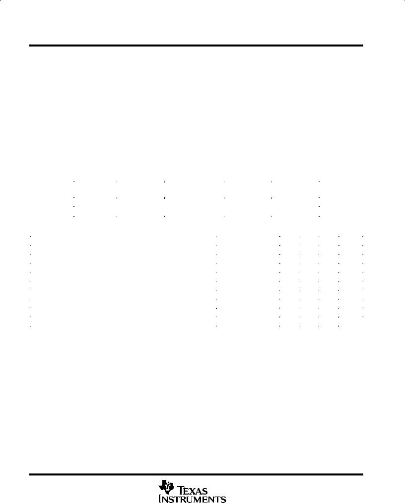
DW OR N PACKAGE
(TOP VIEW)
VPO+ |
|
1 |
20 |
|
VBB |
|
|
|
|||||
|
|
|||||
ANLG GND |
|
2 |
19 |
|
VFXI+ |
|
VPO± |
|
3 |
18 |
|
VFXI± |
|
|
|
|||||
VPI |
|
4 |
17 |
|
GSX |
|
|
|
|||||
VFRO |
|
5 |
16 |
|
ANLG LOOP |
|
|
|
|||||
VCC |
|
|
|
|
|
|
|
6 |
15 |
|
TSX |
|
|
|
|
|
||||
FSR |
|
7 |
14 |
|
FSX |
|
DR |
|
8 |
13 |
|
DX |
|
|
|
|||||
BCLKR/CLKSEL |
9 |
12 |
|
BCLKX |
||
|
||||||
MCLKR/PDN |
10 |
11 |
|
MCLKX |
||
|
||||||
|
|
|
|
|
|
|
These devices are designed to perform the transmit encoding (A/D conversion) and receive decoding (D/A conversion) as well as the transmit and receive filtering functions in a PCM system. They are intended to be used at the analog termination of a PCM line or trunk. The devices require two transmit and receive master clocks that may be asynchronous (1.536 MHz, 1.544 MHz, or 2.048 MHz), transmit and receive data clocks that are synchronous with the master clock (but can vary from 64 kHz to 2.048 MHz), and transmit and receive frame-sync pulses. The TP3064A, TP3067A, TP13064A, and TP13067A provide the band-pass filtering of the analog signals prior to encoding and after decoding of voice and call progress tones. The TP3067A and TP13067A contain patented circuitry to achieve low transmit channel idle noise and are not recommended for applications in which the composite signals on the transmit side are below ±55 dBm0.
The TP3064A and TP3067A are characterized for operation from 0°C to 70°C. The TP13064A and TP13067A are characterized for operation from ±40°C to 85°C.
These devices have limited built-in ESD protection. The leads should be shorted together or the device placed in conductive foam during storage or handling to prevent electrostatic damage to the CMOS gates.
PRODUCTION DATA information is current as of publication date. Products conform to specifications per the terms of Texas Instruments standard warranty. Production processing does not necessarily include testing of all parameters.
Copyright 1996, Texas Instruments Incorporated
POST OFFICE BOX 655303 •DALLAS, TEXAS 75265 |
1 |

TP3064A, TP3067A, TP13064A, TP13067A MONOLITHIC SERIAL INTERFACE COMBINED PCM CODEC AND FILTER
SCTS025C ± SEPTEMBER 1992 ±REVISED JULY 1996
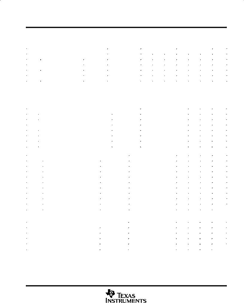
functional block diagram
VFXI ±
VFXI +
VPO+
VPO ±
|
R2 |
|
|
|
|
|
|
|
|
17 |
Analog |
|
|
|
|
|
|
|
|
GSX |
|
Input |
|
|
|
|
|
|
|
|
16 ANLG |
|
18 |
R1 |
|
|
|
|
|
|
|
|
LOOP |
|
|
|
Autozero |
|
|
|
|
|||
|
± |
|
|
|
|
|
|
|
||
|
|
|
|
Logic |
|
|
|
|
||
19 |
|
|
|
|
|
|
|
|
||
+ |
|
|
|
|
|
|
|
|
|
|
|
|
|
|
|
|
|
|
|
|
|
|
R |
|
RC |
Switched- |
|
S/H |
|
|
|
|
|
|
|
Active Filter |
Capacitor |
|
DAC |
|
|
|
|
|
|
|
Band-Pass Filter |
|
|
|
|
|
||
|
|
|
|
|
|
|
|
|
|
|
1 |
|
± |
|
|
|
|
|
|
|
|
|
|
|
|
|
|
|
|
|
|
|
|
|
+ |
|
|
|
|
|
|
|
|
|
R |
|
Voltage |
|
|
A/D |
|
Transmit |
|
|
|
|
|
Reference |
|
Control |
|
Regulator |
13 |
||
|
|
|
|
|
Logic |
|
||||
|
|
|
|
|
|
|
|
|
DX |
|
3 |
|
± |
|
Comparator |
|
|
|
OE |
|
|
|
|
|
|
|
|
|
|
|
||
|
|
|
|
|
|
|
|
|
|
|
|
|
+ |
|
Switched- |
|
|
|
|
|
|
R3 |
|
RC Active |
|
S/H |
|
Receive |
|
|||
|
Capacitor |
|
|
8 |
||||||
|
4 VPI |
|
Filter |
|
DAC |
|
Regulator |
|||
|
|
Low-Pass Filter |
|
DR |
||||||
|
|
|
|
|
|
|
|
CLK |
|
|
R4 |
|
|
|
|
|
|
|
|
|
|
|
5 VFRO |
|
|
|
|
|
|
|
|
|
|
|
|
|
|
Timing and Control |
|
|
15 |
||
|
5 V |
± 5 V |
|
|
|
|
TSX |
|||
|
|
|
|
|
|
|
|
|
||
|
6 |
20 |
2 |
11 |
10 |
12 |
9 |
7 |
14 |
|
|
|
|
|
|
|
|
|
|||
|
VCC |
VBB |
ANLG GND |
MCLKX |
MCLKR/ |
BCLKX |
BCLKR/ |
FSR |
FSX |
|
|
|
|
|
|
PDN |
|
CLKSEL |
|
|
|
2 |
POST OFFICE BOX 655303 •DALLAS, TEXAS 75265 |

TP3064A, TP3067A, TP13064A, TP13067A
MONOLITHIC SERIAL INTERFACE
COMBINED PCM CODEC AND FILTER
SCTS025C ± SEPTEMBER 1992 ±REVISED JULY 1996
|
|
|
|
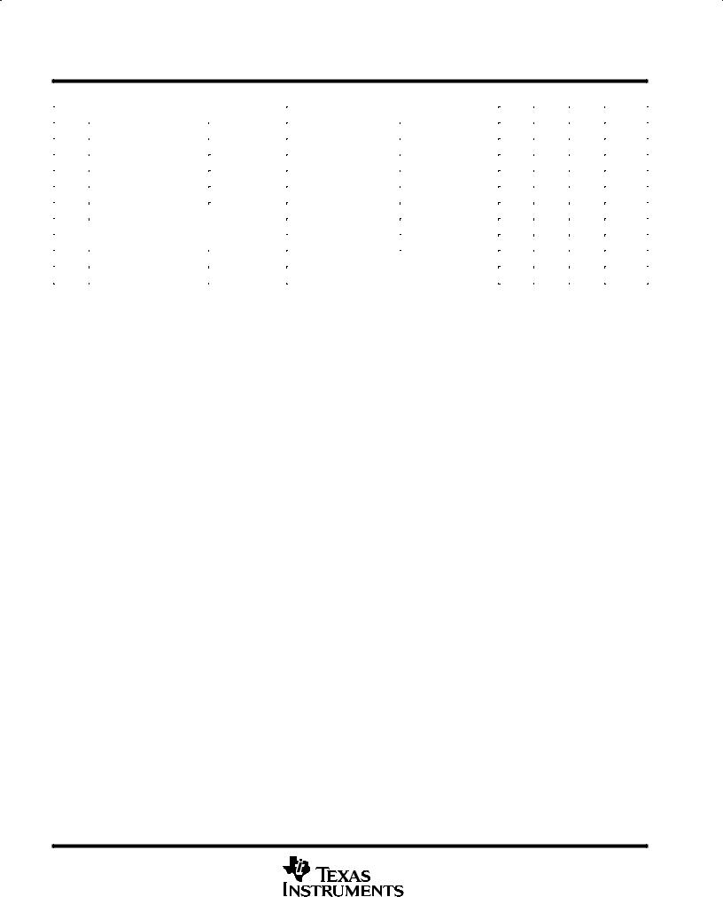
Terminal Functions |
|
|
TERMINAL |
|
DESCRIPTION |
|
|
NAME |
NO. |
|
|
|
|
||
|
|
|
|
|
|
ANLG GND |
2 |
Analog ground. All signals are referenced to ANLG GND. |
|
|
|
|
|
|
|
ANLG LOOP |
16 |
Analog loopback control input. Must be set to logic low for normal operation. When pulled to logic high, the transmit |
|
|
|
|
|
filter input is disconnected from the output of the transmit preamplifier and connected to VPO+ of the receive power |
|
|
|
|
amplifier. |
|
|
|
|
|
|
BCLKR/CLKSEL |
9 |
The bit clock that shifts data into DR after the FSR leading edge. May vary from 64 kHz to 2.048 MHz. Alternately, |
|
|
|
|
|
can be a logic input that selects either 1.536 MHz/1.544 MHz or 2.048 MHz for master clock in synchronous mode. |
|
|
|
|
BCLKX is used for both transmit and receive directions (see Table 1). |
|
|
|
|
|
|
BCLKX |
12 |
The bit clock that shifts out the PCM data on DX. BCLKX can vary from 64 kHz to 2.048 MHz, but must be synchronous |
|
|
|
|
|
with MCLKX. |
|
|
|
|
|
|
DR |
8 |
Receive data input. PCM data is shifted into DR following the FSR leading edge. |
|
|
|
|
|
|
|
DX |
13 |
The 3-state PCM data output that is enabled by FSX. |
|
|
|
|
|
|
|
FSR |
7 |
Receive frame sync pulse input that enables BCLKR to shift PCM data in DR. FSR is an 8-kHz pulse train (see Figures |
|
|
|
|
|
1 and 2 for timing details). |
|
|
|
|
|
|
FSX |
14 |
Transmit frame sync pulse that enables BCLKX to shift out the PCM data on DX. FSX is an 8-kHz pulse train (see |
|
|
|
|
|
Figures 1 and 2 for timing details). |
|
|
|
|
|
|
GSX |
17 |
Analog output of the transmit input amplifier. GSX is used to externally set gain. |
|
|
|
|
|
|
|
MCLKR/PDN |
10 |
Receive master clock (must be 1.536 MHz, 1.544 MHz, or 2.048 MHz). May be synchronous with MCLKX, but should |
|
|
|
|
|
be synchronous for best performance. When MCLKR is connected continuously low, MCLKX is selected for all internal |
|
|
|
|
timing. When MCLKR is connected continuously high, the device is powered down. |
|
|
|
|
|
|
MCLKX |
11 |
Transmit master clock (must be 1.536 MHz, 1.544 MHz, or 2.048 MHz). May be asynchronous with MCLKR |
|
|
|
|
|
|
|
|
|
15 |
Open-drain output that pulses low during the encoder time slot |
|
TSX |
|
||
|
VBB |
20 |
Negative power supply. VBB = ± 5 V ± 5% |
|
|
VCC |
6 |
Positive power supply. VCC = 5 V ± 5% |
|
|
VFRO |
5 |
Analog output of the receive filter |
|
|
|
|
|
|
|
VFXI+ |
19 |
Noninverting input of the transmit input amplifier |
|
|
|
|
|
|
|
VFXI ± |
18 |
Inverting input of the transmit input amplifier |
|
|
|
|
|
|
|
VPI |
4 |
Inverting input to the receive power amplifier. Also powers down both amplifiers when connected to VBB |
|
|
VPO+ |
1 |
The noninverted output of the receive power amplifier |
|
|
|
|
|
|
|
VPO ± |
3 |
The inverted output of the receive power amplifier |
|
|
|
|
|
|
POST OFFICE BOX 655303 •DALLAS, TEXAS 75265 |
3 |
TP3064A, TP3067A, TP13064A, TP13067A
MONOLITHIC SERIAL INTERFACE
COMBINED PCM CODEC AND FILTER
SCTS025C ± SEPTEMBER 1992 ±REVISED JULY 1996
absolute maximum ratings over operating free-air temperature range (unless otherwise noted)²
Supply voltage, VCC (see Note 1) . . . . . . . . . . . . . . . . . . . . . . . . . . . . . . . . . . . . . . . |
. . . . . . . . . . . |
. . . . . . . . . . . 7 |
V |
Supply voltage, VBB (see Note 1) . . . . . . . . . . . . . . . . . . . . . . . . . . . . . . . . . . . . . . . |
. . . . . . . . . . . . |
. . . . . . . . . ±7 V |
|
Voltage range at any analog input or output . . . . . . . . . . . . . . . . . . . . . . . . . . . . . . |
. VCC + 0.3 V to VBB ± 0.3 |
V |
|
Voltage range at any digital input or output . . . . . . . . . . . . . . . . . . . . . . . . . . . . . . . |
VCC + 0.3 V to GND ± 0.3 |
V |
|
Continuous total dissipation . . . . . . . . . . . . . . . . . . . . . . . . . . . . . . . . . . . . . . . . . . . |
See Dissipation Rating Table |
||
Operating free-air temperature range, TA: TP3064A, TP3067A . . . . . . . . . . . . |
. . . . . . . . . . . . |
. . 0°C to 70°C |
|
TP13064A, TP13067A . . . . . . . . . . |
. . . . . . . . . . . . |
±40°C to 85°C |
|
Storage temperature range, Tstg . . . . . . . . . . . . . . . . . . . . . . . . . . . . . . . . . . . . . . . . |
. . . . . . . . . . . |
±65°C to 150°C |
|
Lead temperature 1,6 mm (1/16 inch) from case for 10 seconds: DW or N package . . . . . . . . |
. . . . . . . 260°C |
||
²Stresses beyond those listed under ªabsolute maximum ratingsº may cause permanent damage to the device. These are stress ratings only, and functional operation of the device at these or any other conditions beyond those indicated under ªrecommended operating conditionsº is not implied. Exposure to absolute-maximum-rated conditions for extended periods may affect device reliability.
NOTE 1: All voltages are with respect to GND.
|
DISSIPATION RATING TABLE |
|
|||
PACKAGE |
TA ≤ 25°C |
DERATING FACTOR |
TA = 70°C |
TA = 85°C |
|
POWER RATING |
ABOVE TA = 25°C |
POWER RATING |
POWER RATING |
||
|
|||||
DW |
1025 mW |
8.2 mW/°C |
656 mW |
533 mW |
|
N |
1150 mW |
9.2 mW/°C |
736 mW |
598 mW |
|
|
|
|
|
|
|
recommended operating conditions (see Note 2)
|
|
MIN |
NOM |
MAX |
UNIT |
|
|
|
|
|
|
Supply voltage, VCC |
|
4.75 |
5 |
5.25 |
V |
Supply voltage, VBB |
|
± 4.75 |
± 5 |
± 5.25 |
V |
High-level input voltage, VIH |
|
2.2 |
|
|
V |
Low-level input voltage, VIL |
|
|
|
0.6 |
V |
Common-mode input voltage range, VICR³ |
|
|
|
± 2.5 |
V |
Load resistance at GSX, RL |
|
10 |
|
|
kΩ |
Load capacitance at GSX, CL |
|
|
|
50 |
pF |
Operating free-air temperature, TA |
TP3064A, TP3067A |
0 |
|
70 |
°C |
|
|
|
|
||
TP13064A, TP13067A |
± 40 |
|
85 |
||
|
|
|
|||
|
|
|
|
|
|
³ Measure with CMRR > 60 dB.
NOTE 2: To avoid possible damage to these CMOS devices and resulting reliability problems, the power-up procedure described in the device power-up sequence paragraphs later in this document should be followed.
4 |
POST OFFICE BOX 655303 •DALLAS, TEXAS 75265 |
TP3064A, TP3067A, TP13064A, TP13067A
MONOLITHIC SERIAL INTERFACE
COMBINED PCM CODEC AND FILTER
SCTS025C ± SEPTEMBER 1992 ±REVISED JULY 1996
electrical characteristics over recommended ranges of supply voltage and operating free-air temperature (unless otherwise noted)
supply current
|
PARAMETER |
|
TEST CONDITIONS |
TP306xA |
|
TP1306xA |
|
UNIT |
|
|
|
|
|
|
|
||||
|
|
MIN TYP² |
MAX |
MIN TYP² |
MAX |
||||
|
|
|
|
|
|||||
ICC |
Supply current from VCC |
Power down |
No load |
0.5 |
1 |
0.5 |
1.2 |
mA |
|
|
|
|
|
|
|||||
Active |
6 |
10 |
6 |
11 |
|||||
|
|
|
|
||||||
|
|
|
|
|
|
|
|
|
|
IBB |
Supply current from VBB |
Power down |
No load |
0.5 |
1 |
0.5 |
1.2 |
mA |
|
|
|
|
|
|
|||||
Active |
6 |
10 |
6 |
11 |
|||||
|
|
|
|
||||||
|
|
|
|
|
|
|
|
|
² All typical values are at VCC = 5 V, VBB = ± 5 V, and TA = 25°C.
electrical characteristics at VCC = 5 V ± 5%, VBB = ±5 V ± 5%, GND at 0 V, TA = 25°C (unless otherwise noted)
digital interface
|
PARAMETER |
|
|
|
TEST CONDITIONS |
MIN MAX |
UNIT |
|
|
|
|
|
|
|
|
|
|
VOH |
High-level output voltage |
DX |
IH = ± 3.2 mA |
2.4 |
V |
|||
VOL |
Low-level output voltage |
DX |
IL = 3.2 mA |
0.4 |
V |
|||
|
|
|
|
|
||||
TSX |
IL = 3.2 mA, Drain open |
0.4 |
||||||
|
|
|
||||||
IIH |
High-level input current |
|
|
|
VI = VIH to VCC |
± 10 |
μA |
|
IIL |
Low-level input current |
All digital inputs |
VI = GND to VIL |
± 10 |
μA |
|||
IOZ |
Output current in high-impedance state |
DX |
VO = GND to VCC |
± 10 |
μA |
|||
analog interface with transmit amplifier input
|
|
PARAMETER |
|
TEST CONDITIONS |
MIN |
TYP² |
MAX |
UNIT |
|||
II |
Input current |
|
|
|
|
VFXI+ or VFXI± |
VI = ± 2.5 V to 2.5 V |
|
|
± 200 |
nA |
ri |
Input resistance |
|
|
|
VFXI+ or VFXI± |
VI = ± 2.5 V to 2.5 V |
10 |
|
|
MΩ |
|
ro |
Output resistance |
|
|
|
|
Closed loop, Unit gain |
|
1 |
3 |
Ω |
|
|
Output dynamic range |
|
|
GSX |
RL ≥ 10 kΩ |
|
|
± 2.8 |
V |
||
AV |
Open-loop voltage amplification |
VFXI+ to GSX |
|
5000 |
|
|
|
||||
BI |
Unity-gain bandwidth |
|
|
GSX |
|
1 |
2 |
|
MHz |
||
VIO |
Input offset voltage |
|
|
VFXI+ or VFXI± |
|
|
|
± 20 |
mV |
||
CMRR |
Common-mode rejection ratio |
|
|
60 |
|
|
dB |
||||
|
|
|
|
|
|
|
|
|
|||
kSVR |
Supply-voltage rejection ratio |
|
|
|
60 |
|
|
dB |
|||
² All typical values are at V |
CC |
= 5 V, V |
BB |
= ± 5 V, and T = 25°C. |
|
|
|
|
|
||
|
|
|
|
A |
|
|
|
|
|
||
analog interface with receive filter
|
PARAMETER |
TEST CONDITIONS |
MIN |
TYP² |
MAX |
UNIT |
|
Output resistance |
|
VFRO |
|
|
1 |
3 |
Ω |
|
|
|
|
|
|
|
|
Load resistance |
|
|
VFRO = ± 2.5 V |
600 |
|
|
Ω |
|
|
|
|
|
|
|
|
Load capacitance |
|
VFRO to GND |
|
|
|
500 |
pF |
|
|
|
|
|
|
|
|
Output dc offset voltage |
|
VFRO to GND |
|
|
|
± 200 |
mV |
|
|
|
|
|
|
|
|
² All typical values are at VCC = 5 V, VBB = ± 5 V, and TA = 25°C.
POST OFFICE BOX 655303 •DALLAS, TEXAS 75265 |
5 |
TP3064A, TP3067A, TP13064A, TP13067A
MONOLITHIC SERIAL INTERFACE
COMBINED PCM CODEC AND FILTER
SCTS025C ± SEPTEMBER 1992 ±REVISED JULY 1996
analog interface with power amplifiers
|
PARAMETER |
|
|
TEST CONDITIONS |
MIN TYP² MAX |
UNIT |
|||||
II |
Input current |
|
|
|
|
|
VPI = ± 1 V to 1 V |
|
± 100 |
nA |
|
ri |
Input resistance |
|
|
|
|
|
VPI = ± 1 V to 1 V |
|
10 |
MΩ |
|
ro |
Output resistance |
|
VPO+ or VPO± |
Inverting unity gain |
|
1 |
Ω |
||||
AV |
Voltage amplification |
|
VPO± or VPO+ |
VPO ± = 1.77 Vrms, |
RL = 600 Ω |
± 1 |
|
||||
BI |
Unity-gain bandwidth |
|
VPO± |
Open loop |
|
400 |
kHz |
||||
VIO |
Input offset voltage |
|
|
|
|
|
|
± 25 |
mV |
||
kSVR |
Supply-voltage rejection ratio of VCC or VBB |
VPO ± connected to VPI |
0 kHz to 4 kHz |
60 |
dB |
||||||
|
|
||||||||||
4 kHz to 50 kHz |
36 |
||||||||||
|
|
|
|
|
|
|
|
|
|||
|
|
|
|
|
|
|
|
|
|
|
|
RL |
Load resistance |
|
|
|
|
|
Connected from VPO+ to VPO ± |
600 |
Ω |
||
CL |
Load capacitance |
|
|
|
|
|
|
100 |
pF |
||
² All typical values are at V |
CC |
= 5 V, V |
BB |
= ± 5 V, and T = 25°C. |
|
|
|
||||
|
|
|
|
|
A |
|
|
|
|||
6 |
POST OFFICE BOX 655303 •DALLAS, TEXAS 75265 |
 Loading...