


 Loading...
|
TMP421 |
|
TMP422 |
www.ti.com |
TMP423 |
SBOS398B–JULY 2007–REVISED MARCH 2008
±1°C Remote and Local TEMPERATURE SENSOR
in SOT23-8
FEATURES
∙SOT23-8 PACKAGE
∙±1°C REMOTE DIODE SENSOR (MAX)
∙±1.5°C LOCAL TEMPERATURE SENSOR (MAX)
∙SERIES RESISTANCE CANCELLATION
∙n-FACTOR CORRECTION
∙TWO-WIRE/SMBus™ SERIAL INTERFACE
∙MULTIPLE INTERFACE ADDRESSES
∙DIODE FAULT DETECTION
∙RoHS COMPLIANT AND NO Sb/Br
APPLICATIONS
∙PROCESSOR/FPGA TEMPERATURE MONITORING
∙LCD/DLP®/LCOS PROJECTORS
∙SERVERS
∙CENTRAL OFFICE TELECOM EQUIPMENT
∙STORAGE AREA NETWORKS (SAN)
DESCRIPTION
The TMP421, TMP422, and TMP423 are remote temperature sensor monitors with a built-in local temperature sensor. The remote temperature sensor diode-connected transistors are typically low-cost, NPNor PNP-type transistors or diodes that are an integral part of microcontrollers, microprocessors, or FPGAs.
Remote accuracy is ±1°C for multiple IC manufacturers, with no calibration needed. The two-wire serial interface accepts SMBus write byte, read byte, send byte, and receive byte commands to configure the device.
The TMP421, TMP422, and TMP423 include series resistance cancellation, programmable non-ideality factor, wide remote temperature measurement range (up to +150°C), and diode fault detection.
The TMP421, TMP422, and TMP423 are all available in a SOT23-8 package.
+5V
TMP421 |
TMP422 |
TMP423 |
|
|
|
|
|
8 |
|
1 DXP |
1 DX1 |
1 DXP1 |
V+ |
7 |
SCL |
||||
|
|
|
|
SMBus |
2 |
2 |
2 |
|
Controller |
SDA |
6 |
|||
DXN |
DX2 |
DXP2 |
|
|
3 |
|
|
|
|
A1 |
3 |
3 |
|
|
|
DX3 |
DXP3 |
|
|
4 |
4 |
4 |
|
|
A0 |
|
|
||
|
DX4 |
DXN |
|
|
|
|
|
GND |
|
|
|
|
5 |
|
1 Channel Local |
1 Channel Local |
1 Channel Local |
|
|
1 Channel Remote |
2 Channels Remote |
3 Channels Remote |
|
|
Please be aware that an important notice concerning availability, standard warranty, and use in critical applications of Texas Instruments semiconductor products and disclaimers thereto appears at the end of this data sheet.
DLP is a registered trademark of Texas Instruments. SMBus is a trademark of Intel Corporation.
All other trademarks are the property of their respective owners.
PRODUCTION DATA information is current as of publication date. |
Copyright © 2007–2008, Texas Instruments Incorporated |
Products conform to specifications per the terms of the Texas |
|
Instruments standard warranty. Production processing does not |
|
necessarily include testing of all parameters. |
|

TMP421
TMP422
TMP423
www.ti.com
SBOS398B–JULY 2007–REVISED MARCH 2008
This integrated circuit can be damaged by ESD. Texas Instruments recommends that all integrated circuits be handled with appropriate precautions. Failure to observe proper handling and installation procedures can cause damage.
ESD damage can range from subtle performance degradation to complete device failure. Precision integrated circuits may be more susceptible to damage because very small parametric changes could cause the device not to meet its published specifications.
PACKAGE INFORMATION(1)
|
|
TWO-WIRE |
|
PACKAGE |
PACKAGE |
PRODUCT |
DESCRIPTION |
ADDRESS |
PACKAGE-LEAD |
DESIGNATOR |
MARKING |
|
Single Channel |
|
|
|
|
TMP421 |
Remote Junction |
100 11xx |
SOT23-8 |
DCN |
DACI |
|
Temperature Sensor |
|
|
|
|
|
Dual Channel |
|
|
|
|
TMP422 |
Remote Junction |
100 11xx |
SOT23-8 |
DCN |
DADI |
|
Temperature Sensor |
|
|
|
|
TMP423A |
Triple Channel |
100 1100 |
SOT23-8 |
DCN |
DAEI |
TMP423B |
Remote Junction |
100 1101 |
SOT23-8 |
DCN |
DAFI |
Temperature Sensor |
(1)For the most current package and ordering information see the Package Option Addendum at the end of this document, or see the TI web site at www.ti.com.
ABSOLUTE MAXIMUM RATINGS(1)
Over operating free-air temperature range, unless otherwise noted.
|
|
TMP421, TMP422, TMP423 |
UNIT |
|
Power Supply, VS |
|
+7 |
V |
|
Input Voltage |
Pins 1, 2, 3, and 4 only |
–0.5 to VS + 0.5 |
V |
|
Pins 6 and 7 only |
–0.5 to 7 |
V |
||
|
||||
Input Current |
|
10 |
mA |
|
Operating Temperature Range |
–55 to +127 |
°C |
||
Storage Temperature Range |
–60 to +130 |
°C |
||
Junction Temperature (TJ max) |
+150 |
°C |
||
|
Human Body Model (HBM) |
3000 |
V |
|
ESD Rating |
Charged Device Model (CDM) |
1000 |
V |
|
|
Machine Model (MM) |
200 |
V |
|
(1)Stresses above these ratings may cause permanent damage. Exposure to absolute maximum conditions for extended periods may degrade device reliability. These are stress ratings only, and functional operation of the device at these or any other conditions beyond those specified is not implied.
2 |
Submit Documentation Feedback |
Copyright © 2007–2008, Texas Instruments Incorporated |
Product Folder Link(s): TMP421 TMP422 TMP423

TMP421 TMP422
TMP423
www.ti.com
SBOS398B–JULY 2007–REVISED MARCH 2008
ELECTRICAL CHARACTERISTICS
At TA = –40°C to +125°C and VS = 2.7V to 5.5V, unless otherwise noted.
|
|
|
TMP421, TMP422, TMP423 |
|
||
PARAMETER |
|
CONDITIONS |
MIN |
TYP |
MAX |
UNIT |
TEMPERATURE ERROR |
|
|
|
|
|
|
Local Temperature Sensor |
TELOCAL |
TA = –40°C to +125°C |
|
±1.25 |
±2.5 |
°C |
|
|
TA = +15°C to +85°C, VS = 3.3V |
|
±0.25 |
±1.5 |
°C |
Remote Temperature Sensor(1) |
TEREMOTE |
TA = +15°C to +85°C, TD = –40°C to +150°C, VS = 3.3V |
|
±0.25 |
±1 |
°C |
|
|
TA = –40°C to +100°C, TD = –40°C to +150°C, VS = 3.3V |
|
±1 |
±3 |
°C |
|
|
TA = –40°C to +125°C, TD = –40°C to +150°C |
|
±3 |
±5 |
°C |
vs Supply (Local/Remote) |
|
VS = 2.7V to 5.5V |
|
±0.2 |
±0.5 |
°C/V |
TEMPERATURE MEASUREMENT |
|
|
|
|
|
|
Conversion Time (per channel) |
|
|
100 |
115 |
130 |
ms |
Resolution |
|
|
|
|
|
|
Local Temperature Sensor (programmable) |
|
|
12 |
|
Bits |
|
Remote Temperature Sensor |
|
|
|
12 |
|
Bits |
Remote Sensor Source Currents |
|
|
|
|
|
|
High |
|
Series Resistance 3kΩ Max |
|
120 |
|
μA |
Medium High |
|
|
|
60 |
|
μA |
Medium Low |
|
|
|
12 |
|
μA |
Low |
|
|
|
6 |
|
μA |
Remote Transistor Ideality Factor |
η |
TMP421/22/23 Optimized Ideality Factor |
|
1.008 |
|
|
SMBus INTERFACE |
|
|
|
|
|
|
Logic Input High Voltage (SCL, SDA) |
VIH |
|
2.1 |
|
|
V |
Logic Input Low Voltage (SCL, SDA) |
VIL |
|
|
|
0.8 |
V |
Hysteresis |
|
|
|
500 |
|
mV |
SMBus Output Low Sink Current |
|
|
6 |
|
|
mA |
SDA Output Low Voltage |
VOL |
IOUT = 6mA |
|
0.15 |
0.4 |
V |
Logic Input Current |
|
0 ≤ VIN ≤ 6V |
–1 |
|
+1 |
μA |
SMBus Input Capacitance (SCL, SDA) |
|
|
|
3 |
|
pF |
SMBus Clock Frequency |
|
|
|
|
3.4 |
MHz |
SMBus Timeout |
|
|
25 |
30 |
35 |
ms |
SCL Falling Edge to SDA Valid Time |
|
|
|
|
1 |
μs |
DIGITAL INPUTS |
|
|
|
|
|
|
Input Capacitance |
|
|
|
3 |
|
pF |
Input Logic Levels |
|
|
|
|
|
|
Input High Voltage |
VIH |
|
0.7(V+) |
|
(V+)+0.5 |
V |
Input Low Voltage |
VIL |
|
–0.5 |
|
0.3(V+) |
V |
Leakage Input Current |
IIN |
0V ≤ VIN ≤ VS |
|
|
1 |
μA |
POWER SUPPLY |
|
|
|
|
|
|
Specified Voltage Range |
VS |
|
2.7 |
|
5.5 |
V |
Quiescent Current |
IQ |
0.0625 Conversions per Second |
|
32 |
38 |
μA |
|
|
Eight Conversions per Second |
|
400 |
525 |
μA |
|
|
Serial Bus Inactive, Shutdown Mode |
|
3 |
10 |
μA |
|
|
Serial Bus Active, fS = 400kHz, Shutdown Mode |
|
90 |
|
μA |
|
|
Serial Bus Active, fS = 3.4MHz, Shutdown Mode |
|
350 |
|
μA |
Undervoltage Lockout |
UVLO |
|
2.3 |
2.4 |
2.6 |
V |
Power-On Reset Threshold |
POR |
|
|
1.6 |
2.3 |
V |
TEMPERATURE RANGE |
|
|
|
|
|
|
Specified Range |
|
|
–40 |
|
+125 |
°C |
Storage Range |
|
|
–60 |
|
+130 |
°C |
Thermal Resistance, SOT23 |
θJA |
|
|
100 |
|
°C/W |
(1)Tested with less than 5Ω effective series resistance and 100pF differential input capacitance.
Copyright © 2007–2008, Texas Instruments Incorporated |
Submit Documentation Feedback |
3 |
Product Folder Link(s): TMP421 TMP422 TMP423

TMP421
TMP422
TMP423 |
|
|
|
|
|
|
|
|
www.ti.com |
SBOS398B–JULY 2007–REVISED MARCH 2008 |
|
|
|
|
|
|
|||
|
|
TMP421 PIN CONFIGURATION |
|||||||
|
|
|
|
|
DCN PACKAGE |
|
|
||
|
|
|
|
|
SOT23-8 |
|
|
||
|
|
|
|
|
(TOP VIEW) |
|
|
||
|
|
|
|
|
|
|
|
|
V+ |
|
|
|
|
|
|
|
|
|
|
|
|
DXP |
1 |
|
|
|
8 |
||
|
|
|
|
|
|
|
|
|
SCL |
|
|
|
|
|
|
|
|
|
|
|
|
DXN |
2 |
|
|
|
7 |
||
|
|
|
|
|
TMP421 |
|
|
|
|
|
|
|
|
|
|
|
|
||
|
|
A1 |
3 |
|
|
|
6 |
SDA |
|
|
|
A0 |
|
|
|
|
|
GND |
|
|
|
|
|
|
|
|
|||
|
|
4 |
|
|
|
5 |
|||
|
|
|
|
|
|
|
|
|
|
|
|
|
|
|
|
|
|
||
|
|
TMP421 PIN ASSIGNMENTS |
|||||||
|
TMP421 |
|
|
|
|
|
|
|
|
NO. |
NAME |
DESCRIPTION |
|
|
|
|
|
|
|
1 |
DXP |
Positive connection to remote temperature sensor. |
|
|
|||||
2 |
DXN |
Negative connection to remote temperature sensor. |
|
|
|||||
3 |
A1 |
Address pin |
|
|
|
|
|
|
|
4 |
A0 |
Address pin |
|
|
|
|
|
|
|
5 |
GND |
Ground |
|
|
|
|
|
|
|
6 |
SDA |
Serial data line for SMBus, open-drain; requires pull-up resistor to V+. |
|||||||
7 |
SCL |
Serial clock line for SMBus, open-drain; requires pull-up resistor to V+. |
|||||||
8 |
V+ |
Positive supply voltage (2.7V to 5.5V) |
|
|
|||||
|
|
TMP422 PIN CONFIGURATION |
|||||||
|
|
|
|
|
DCN PACKAGE |
|
|
||
|
|
|
|
|
SOT23-8 |
|
|
||
|
|
|
|
|
(TOP VIEW) |
|
|
||
|
|
|
|
|
|
|
|
|
V+ |
|
|
|
|
|
|
|
|
|
|
|
|
DX1 |
|
1 |
|
|
|
8 |
|
|
|
|
|
|
|
|
|
|
SCL |
|
|
|
|
|
|
|
|
||
|
|
DX2 |
|
2 |
|
|
|
7 |
|
|
|
|
|
|
TMP422 |
|
|
|
|
|
|
|
|
|
|
|
|
||
|
|
DX3 |
|
3 |
|
|
|
6 |
SDA |
|
|
|
|
|
|
|
|
|
GND |
|
|
|
|
|
|
|
|
||
|
|
DX4 |
|
4 |
|
|
|
5 |
|
|
|
|
|
|
|
|
|||
|
|
|
|
|
|||||
|
|
TMP422 PIN ASSIGNMENTS |
|||||||
|
TMP422 |
|
|
|
|
|
|
|
|
NO. |
NAME |
DESCRIPTION |
|
|
|
|
|
|
|
1 |
DX1 |
Channel 1 remote temperature sensor connection pin. Also sets the TMP422 address; see Table 10. |
|||||||
2 |
DX2 |
Channel 1 remote temperature sensor connection pin. Also sets the TMP422 address; see Table 10. |
|||||||
3 |
DX3 |
Channel 2 remote temperature sensor connection pin. Also sets the TMP422 address; see Table 10. |
|||||||
4 |
DX4 |
Channel 2 remote temperature sensor connection pin. Also sets the TMP422 address; see Table 10. |
|||||||
5 |
GND |
Ground |
|
|
|
|
|
|
|
6 |
SDA |
Serial data line for SMBus, open-drain; requires pull-up resistor to V+. |
|||||||
7 |
SCL |
Serial clock line for SMBus, open-drain; requires pull-up resistor to V+. |
|||||||
8 |
V+ |
Positive supply voltage (2.7V to 5.5V) |
|
|
|||||
4 |
Submit Documentation Feedback |
Copyright © 2007–2008, Texas Instruments Incorporated |
Product Folder Link(s): TMP421 TMP422 TMP423

TMP421 TMP422
TMP423
www.ti.com
SBOS398B–JULY 2007–REVISED MARCH 2008
TMP423 PIN CONFIGURATION
DCN PACKAGE
SOT23-8
(TOP VIEW)
|
|
|
|
V+ |
DXP1 |
1 |
|
8 |
|
|
|
|
|
SCL |
|
|
|
|
|
DXP2 |
2 |
|
7 |
|
|
|
TMP423 |
|
|
|
|
|
|
|
DXP3 |
3 |
|
6 |
SDA |
DXN |
|
|
|
GND |
|
|
|
||
4 |
|
5 |
||
|
|
|
|
|
|
|
|
|
|
|
|
TMP423 PIN ASSIGNMENTS |
|
TMP423 |
|
NO. |
NAME |
DESCRIPTION |
1 |
DXP1 |
Channel 1 positive connection to remote temperature sensor. |
2 |
DXP2 |
Channel 2 positive connection to remote temperature sensor. |
3 |
DXP3 |
Channel 3 positive connection to remote temperature sensor. |
4 |
DXN |
Common negative connection to remote temperature sensors, Channel 1, Channel 2, Channel 3. |
5 |
GND |
Ground |
6 |
SDA |
Serial data line for SMBus, open-drain; requires pull-up resistor to V+. |
7 |
SCL |
Serial clock line for SMBus, open-drain; requires pull-up resistor to V+. |
8 |
V+ |
Positive supply voltage (2.7V to 5.5V) |
Copyright © 2007–2008, Texas Instruments Incorporated |
Submit Documentation Feedback |
5 |
Product Folder Link(s): TMP421 TMP422 TMP423
TMP421
TMP422
TMP423
www.ti.com
SBOS398B–JULY 2007–REVISED MARCH 2008
TYPICAL CHARACTERISTICS
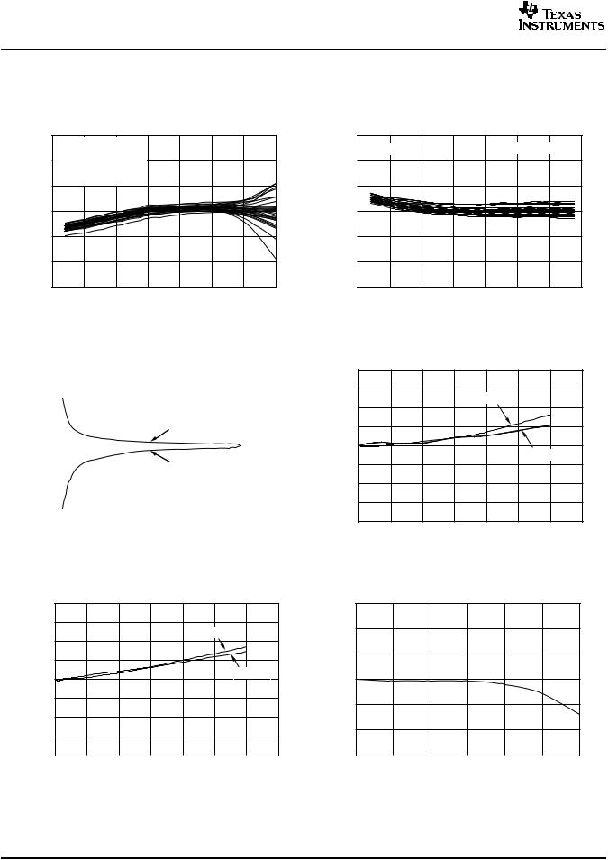
At TA = +25°C and VS = +5.0V, unless otherwise noted.
RemoteTemperatureError(°C)
REMOTE TEMPERATURE ERROR |
LOCAL TEMPERATURE ERROR |
vs TEMPERATURE |
vs TEMPERATURE |
3 |
VS |
= 3.3V |
|
|
|
|
|
|
3 |
|
|
|
|
|
|
|
|
|
|
|
|
|
|
|
VS = 3.3V |
|
|
|
50 Units Shown |
|
|||
|
TREMOTE = +25°C |
|
|
|
|
|
|
|
|
|
|
|||||
2 |
|
|
|
|
°C) |
2 |
|
|
|
|
|
|
|
|||
30 Typical Units Shown |
|
|
|
|
|
|
|
|
|
|
|
|||||
|
|
|
|
|
|
|
|
|
|
|
|
|
||||
|
η = 1.008 |
|
|
|
|
|
( |
|
|
|
|
|
|
|
|
|
|
|
|
|
|
|
Error |
|
|
|
|
|
|
|
|
||
1 |
|
|
|
|
|
|
|
1 |
|
|
|
|
|
|
|
|
−2 |
|
|
|
|
|
|
|
LocalTemperature |
−2 |
|
|
|
|
|
|
|
0 |
|
|
|
|
|
|
|
|
0 |
|
|
|
|
|
|
|
−1 |
|
|
|
|
|
|
|
|
−1 |
|
|
|
|
|
|
|
−3 |
|
|
|
|
|
|
|
|
−3 |
|
|
|
|
|
|
|
|
−50 |
−25 |
0 |
25 |
50 |
75 |
100 |
125 |
−50 |
−25 |
0 |
25 |
50 |
75 |
100 |
125 |
|
|
|
|
|
|
|
|
|
||||||||
|
|
|
Ambient Temperature, TA (°C) |
|
|
|
|
Ambient Temperature, TA (°C) |
|
|
||||||
Figure 1.
REMOTE TEMPERATURE ERROR vs LEAKAGE RESISTANCE
°C) |
60 |
|
|
|
|
|
|
|
|
|
|
|
|
|
40 |
|
|
|
|
|
|
|
|
|
|
|
|
|
|
|
|
|
|
|
|
|
|
|
|
|
|
|
||
( |
|
|
|
|
|
|
|
|
|
|
|
|
|
|
emperatureErrorRemoteT |
20 |
|
|
|
|
|
|
|
|
|
|
|
|
|
|
|
|
|
|
|
|
R −GND |
|
|
|
|
|
||
|
|
|
|
|
|
|
|
|
|
|
|
|
||
|
0 |
|
|
|
|
|
|
|
|
|
|
|
|
|
|
|
|
|
|
|
|
|
R −VS |
|
|
|
|
|
|
|
|
|
|
|
|
|
|
|
|
|
|
|
|
|
|
−20 |
|
|
|
|
|
|
|
|
|
|
|
|
|
|
|
|
|
|
|
|
|
|
|
|
|
|
|
|
|
−40 |
|
|
|
|
|
|
|
|
|
|
|
|
|
|
|
|
|
|
|
|
|
|
|
|
|
|
|
|
|
−60 |
|
|
|
|
|
|
|
|
|
|
|
|
|
|
|
|
|
|
|
|
|
|
|
|
|
|
|
|
|
0 |
5 |
10 |
15 |
20 |
25 |
30 |
|||||||
Leakage Resistance (MΩ )
Figure 3.
REMOTE TEMPERATURE ERROR vs SERIES RESISTANCE (GND Collector-Connected Transistor, 2N3906 PNP)
|
2.0 |
|
|
|
|
|
|
|
°C) |
1.5 |
|
|
|
|
|
|
|
|
|
|
|
VS = 2.7V |
|
|
||
( |
|
|
|
|
|
|
||
RemoteTemperatureError |
1.0 |
|
|
|
|
|
|
|
0.5 |
|
|
|
|
|
|
|
|
0 |
|
|
|
|
|
VS = 5.5V |
||
|
|
|
|
|
|
|
||
−0.5 |
|
|
|
|
|
|
|
|
−1.0 |
|
|
|
|
|
|
|
|
−1.5 |
|
|
|
|
|
|
|
|
|
|
|
|
|
|
|
|
|
|
−2.0 |
|
|
|
|
|
|
|
|
0 |
500 |
1000 |
1500 |
2000 |
2500 |
3000 |
3500 |
|
|
|
|
RS ( Ω ) |
|
|
|
|
Figure 5.
Figure 2.
REMOTE TEMPERATURE ERROR vs SERIES RESISTANCE (Diode-Connected Transistor, 2N3906 PNP)
|
2.0 |
|
|
|
|
|
|
|
°C) |
1.5 |
|
|
|
|
|
|
|
|
|
|
|
VS = 2.7V |
|
|
|
|
( |
|
|
|
|
|
|
|
|
RemoteTemperatureError |
1.0 |
|
|
|
|
|
|
|
0.5 |
|
|
|
|
|
|
|
|
0 |
|
|
|
|
|
|
|
|
|
|
|
|
|
|
VS = 5.5V |
|
|
−0.5 |
|
|
|
|
|
|
|
|
−1.0 |
|
|
|
|
|
|
|
|
−1.5 |
|
|
|
|
|
|
|
|
|
|
|
|
|
|
|
|
|
|
−2.0 |
|
|
|
|
|
|
|
|
0 |
500 |
1000 |
1500 |
2000 |
2500 |
3000 |
3500 |
|
|
|
|
RS ( Ω ) |
|
|
|
|
Figure 4.
REMOTE TEMPERATURE ERROR vs DIFFERENTIAL CAPACITANCE
|
3 |
°C) |
2 |
( |
|
emperatureErrorRemoteT |
1 |
|
0 |
|
−1 |
|
−2 |
|
−3 |
0 |
0.5 |
1.0 |
1.5 |
2.0 |
2.5 |
3.0 |
Capacitance (nF)
Figure 6.
6 |
Submit Documentation Feedback |
Copyright © 2007–2008, Texas Instruments Incorporated |
Product Folder Link(s): TMP421 TMP422 TMP423

TMP421 TMP422
TMP423
www.ti.com
SBOS398B–JULY 2007–REVISED MARCH 2008
TYPICAL CHARACTERISTICS (continued)
At TA = +25°C and VS = +5.0V, unless otherwise noted.
|
|
TEMPERATURE ERROR |
|
|
|
|
vs POWER-SUPPLY NOISE FREQUENCY |
|
|
|
25 |
|
Local 100mVPP Noise |
|
|
|
|
|
|
|
20 |
|
Remote 100mVPP Noise |
|
|
|
|
|
|
°C) |
15 |
|
Local 250mVPP Noise |
|
10 |
|
Remote 250mVPP Noise |
|
|
( |
|
|
|
|
TemperatureError |
5 |
|
|
|
|
0 |
|
|
|
|
−5 |
|
|
|
|
−10 |
|
|
|
|
−15 |
|
|
|
|
−20 |
|
|
|
|
−25 |
|
|
|
|
0 |
5 |
10 |
15 |
Frequency (MHz)
Figure 7.
|
SHUTDOWN QUIESCENT CURRENT |
||
|
vs SCL CLOCK FREQUENCY |
||
|
500 |
|
|
|
450 |
|
|
|
400 |
|
|
|
350 |
|
|
( A) |
300 |
|
|
250 |
|
|
|
Q |
V |
S |
= 5.5V |
I |
|
|
|
|
200 |
|
|
|
150 |
|
|
|
100 |
|
|
|
50 |
|
|
|
0 |
|
VS = 3.3V |
|
|
|
|
1k |
10k |
100k |
1M |
10M |
SCL CLock Frequency (Hz)
Figure 9.
QUIESCENT CURRENT vs CONVERSION RATE
|
500 |
|
|
|
|
|
|
|
|
450 |
|
|
|
|
|
|
|
|
400 |
|
|
|
|
|
|
|
|
350 |
|
|
|
|
|
|
|
A) |
300 |
|
|
|
|
VS = 5.5V |
|
|
|
|
|
|
|
|
|
||
( |
250 |
|
|
|
|
|
|
|
Q |
|
|
|
|
|
|
|
|
I |
200 |
|
|
|
|
|
|
|
|
|
|
|
|
|
|
|
|
|
150 |
|
|
|
|
|
|
|
|
100 |
|
|
|
|
|
VS = 2.7V |
|
|
|
|
|
|
|
|
|
|
|
50 |
|
|
|
|
|
|
|
|
0 |
|
|
|
|
|
|
|
|
0.0625 |
0.125 |
0.25 |
0.5 |
1 |
2 |
4 |
8 |
|
|
|
Conversion Rate (conversions/sec) |
|
||||
Figure 8.
SHUTDOWN QUIESCENT CURRENT vs SUPPLY VOLTAGE
|
8 |
|
|
|
|
|
|
|
7 |
|
|
|
|
|
|
|
6 |
|
|
|
|
|
|
|
5 |
|
|
|
|
|
|
( A) |
4 |
|
|
|
|
|
|
Q |
|
|
|
|
|
|
|
I |
|
|
|
|
|
|
|
|
3 |
|
|
|
|
|
|
|
2 |
|
|
|
|
|
|
|
1 |
|
|
|
|
|
|
|
0 |
|
|
|
|
|
|
|
2.5 |
3.0 |
3.5 |
4.0 |
4.5 |
5.0 |
5.5 |
|
|
|
|
VS (V) |
|
|
|
Figure 10.
Copyright © 2007–2008, Texas Instruments Incorporated |
Submit Documentation Feedback |
7 |
Product Folder Link(s): TMP421 TMP422 TMP423
TMP421
TMP422
TMP423
www.ti.com
SBOS398B–JULY 2007–REVISED MARCH 2008
APPLICATION INFORMATION
The TMP421 (two-channel), TMP422 (three-channel), and TMP423 (four-channel) are digital temperature sensors that combine a local die temperature measurement channel and one, two, or three remote junction temperature measurement channels in a single SOT23-8 package. These devices are two-wire- and SMBus interface-compatible and are specified over a temperature range of –40°C to +125°C. The TMP421/22/23 each contain multiple registers for holding configuration information and temperature measurement results.
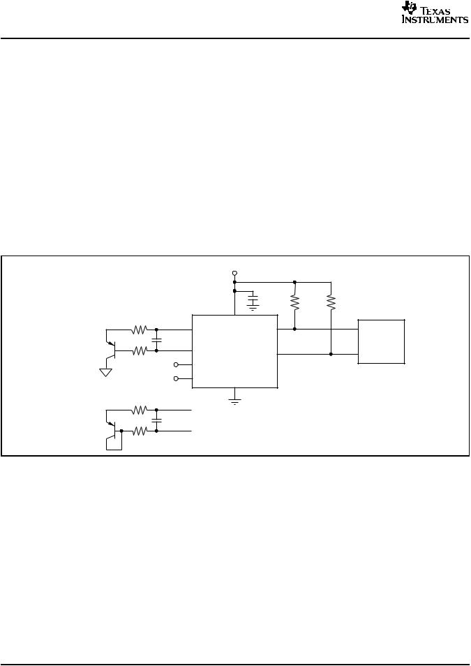
For proper remote temperature sensing operation, the TMP421 requires only a transistor connected between DXP and DXN pins. If the remote channel is not utilized, DXP can be left open or tied to GND.
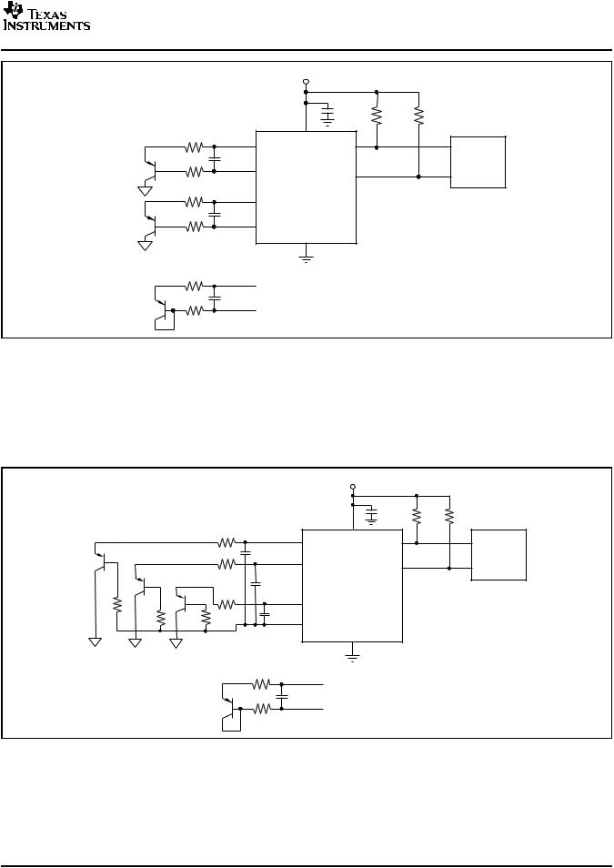
The TMP422 requires transistors connected between DX1 and DX2 and between DX3 and DX4. Unused channels on the TMP422 must be connected to GND. The TMP423 requires a transistor connected to each positive channel (DXP1, DXP2, and DXP3), with the base of each channel tied to the common negative, DXN. For an unused channel, the TMP423 DXP pin can be left open or tied to GND.
The TMP421/22/23 SCL and SDA interface pins each require pull-up resistors as part of the communication bus. A 0.1μF power-supply bypass capacitor is recommended for local bypassing. Figure 11 shows a typical configuration for the TMP421; Figure 12 illustrates a typical application for the TMP422. Figure 13 illustrates a typical application for the TMP423.
|
|
|
|
+5V |
|
|
|
Transistor-connected configuration(1): |
|
|
0.1µF |
10kΩ |
10kΩ |
||
Series Resistance |
|
8 |
|
(typ) |
(typ) |
||
|
|
|
|
||||
RS(2) |
|
1 |
V+ |
7 |
|
|
|
|
|
|
|
|
|
||
|
|
|
|
SCL |
|
|
|
|
|
|
DXP |
|
|
|
|
R |
|
CDIFF |
|
|
|
SMBus |
|
(2) |
|
|
|
|
|||
|
|
(3) |
|
|
|
|
|
|
S |
|
2 |
|
|
|
Controller |
|
|
|
|
6 |
|
||
|
|
|
DXN |
TMP421 |
|
|
|
|
|
|
SDA |
|
|
||
|
|
|
3 |
|
|
|
|
|
|
|
A1 |
|
|
|
|
|
|
|
4 |
|
|
|
|
|
|
|
A0 |
GND |
|
|
|
|
|
|
|
|
|
|
|
Diode-connected configuration(1): |
|
|
5 |
|
|
|
|
R |
(2) |
|
|
|
|
|
|
|
S |
|
|
|
|
|
|
|
|
(3) |
|
|
|
|
|
R |
(2) |
CDIFF |
|
|
|
|
|
|
S |
|
|
|
|
|
|
(1)Diode-connected configuration provides better settling time. Transistor-connected configuration provides better series resistance cancellation.
(2)RS (optional) should be < 1.5kΩ in most applications. Selection of RS depends on application; see the Filtering section.
(3)CDIFF (optional) should be < 1000pF in most applications. Selection of CDIFF depends on application; see the Filtering section and Figure 6, Remote Temperature Error vs Differential Capacitance.
Figure 11. TMP421 Basic Connections
8 |
Submit Documentation Feedback |
Copyright © 2007–2008, Texas Instruments Incorporated |
Product Folder Link(s): TMP421 TMP422 TMP423
TMP421 TMP422
TMP423
www.ti.com
SBOS398B–JULY 2007–REVISED MARCH 2008
|
|
|
|
+5V |
|
|
|
Transistor-connected configuration(1): |
|
|
0.1µF |
10kΩ |
10kΩ |
||
Series Resistance |
|
8 |
|
(typ) |
(typ) |
||
|
|
|
|
||||
RS(2) |
|
1 |
V+ |
7 |
|
|
|
|
|
|
|
|
|
||
|
|
|
DX1(4) |
|
SCL |
|
|
DXP1 |
(2) |
(3) |
|
|
|
|
SMBus |
|
|
|
|
|
|||
R |
CDIFF |
|
|
|
|
||
|
S |
|
2 |
|
|
|
Controller |
|
|
|
|
|
|
||
|
|
|
DX2(4) |
|
6 |
|
|
DXN1 |
|
|
|
|
SDA |
|
|
|
|
|
|
|
|
|
|
R |
(2) |
|
|
TMP422 |
|
|
|
|
S |
|
3 |
|
|
|
|
|
|
|
|
|
|
|
|
|
|
|
DX3(4) |
|
|
|
|
DXP2 |
(2) |
(3) |
|
|
|
|
|
|
|
|
|
|
|
||
R |
CDIFF |
|
|
|
|
|
|
|
S |
|
4 |
|
|
|
|
|
|
|
|
|
|
|
|
|
|
|
DX4(4) |
|
|
|
|
DXN2 |
|
|
|
GND |
|
|
|
|
|
|
|
5 |
|
|
|
Diode-connected configuration(1): |
|
|
|
|
|
|
|
R |
(2) |
|
|
|
|
|
|
|
S |
|
|
|
|
|
|
|
|
(3) |
|
|
|
|
|
R |
(2) |
CDIFF |
|
|
|
|
|
|
S |
|
|
|
|
|
|
(1)Diode-connected configuration provides better settling time. Transistor-connected configuration provides better series resistance cancellation.
(2)RS (optional) should be < 1.5kΩ in most applications. Selection of RS depends on application; see the Filtering section.
(3)CDIFF (optional) should be < 1000pF in most applications. Selection of CDIFF depends on application; see the Filtering section and Figure 6, Remote Temperature Error vs Differential Capacitance.
(4)TMP422 SMBus slave address is 1001 100 when connected as shown.
Figure 12. TMP422 Basic Connections
+5V
|
|
Transistor-connected configuration(1): |
|
0.1µF |
10kΩ |
10kΩ |
|||
|
|
|
|
|
|
|
|||
|
|
Series Resistance |
|
|
8 |
(typ) |
(typ) |
||
|
|
|
|
|
|
|
|
|
|
|
|
R |
(2) |
|
|
|
|
|
|
|
|
|
S |
|
1 DXP1 |
V+ |
7 |
|
|
|
|
|
|
|
SCL |
|
|||
|
|
|
(2) |
(3) |
|
|
|
|
SMBus |
|
|
RS |
CDIFF |
2 |
|
|
|
Controller |
|
|
|
|
|
|
DXP2 |
SDA 6 |
|||
|
|
|
|
|
|
|
|||
|
|
|
|
(3) |
|
|
|
|
|
|
|
|
(2) |
CDIFF |
|
|
TMP423 |
|
|
|
|
R |
|
|
|
|
|
|
|
|
|
|
S |
|
3 |
|
|
|
|
|
|
|
|
|
DXP3 |
|
|
|
|
|
|
|
|
|
|
|
|
|
|
R (2) |
R (2) |
R (2) |
|
CDIFF |
(3) |
|
|
|
|
|
4 |
|
|
|
|
||||
S |
S |
S |
|
|
DXN |
|
|
|
|
|
|
|
|
|
|
|
|
|
|
|
|
|
|
|
|
|
GND |
|
|
|
|
|
|
|
|
|
5 |
|
|
|
|
Diode-connected configuration(1): |
|
|
|
|
|||
|
|
|
|
R (2) |
|
|
|
|
|
|
|
|
|
S |
|
|
|
|
|
|
|
|
|
|
|
DXP |
|
|
|
|
|
|
|
R (2) |
|
(3) |
|
|
|
|
|
|
|
CDIFF |
|
|
|
||
|
|
|
|
S |
|
|
|
|
|
|
|
|
|
|
|
DXN |
|
|
|
(1)Diode-connected configuration provides better settling time. Transistor-connected configuration provides better series resistance cancellation.
(2)RS (optional) should be < 1.5kΩ in most applications. Selection of RS depends on application; see the Filtering section.
(3)CDIFF (optional) should be < 1000pF in most applications. Selection of CDIFF depends on application; see the Filtering section and Figure 6, Remote Temperature Error vs Differential Capacitance.
Figure 13. TMP423 Basic Connections
Copyright © 2007–2008, Texas Instruments Incorporated |
Submit Documentation Feedback |
9 |
Product Folder Link(s): TMP421 TMP422 TMP423

TMP421
TMP422
TMP423
SBOS398B–JULY 2007–REVISED MARCH 2008
SERIES RESISTANCE CANCELLATION
Series resistance in an application circuit that typically results from printed circuit board (PCB) trace resistance and remote line length is automatically cancelled by the TMP421/22/23, preventing what would otherwise result in a temperature offset. A total of up to 3kΩ of series line resistance is cancelled by the TMP421/22/23, eliminating the need for additional characterization and temperature offset correction. See the two Remote Temperature Error vs Series Resistance typical characteristic curves (Figure 4 and Figure 5) for details on the effects of series resistance and power-supply voltage on sensed remote temperature error.
DIFFERENTIAL INPUT CAPACITANCE
The TMP421/22/23 tolerate differential input capacitance of up to 1000pF with minimal change in temperature error. The effect of capacitance on sensed remote temperature error is illustrated in Figure 6, Remote Temperature Error vs Differential Capacitance.
TEMPERATURE MEASUREMENT DATA
Temperature measurement data may be taken over an operating range of –40°C to +127°C for both local and remote locations.
However, measurements from –55°C to +150°C can be made both locally and remotely by reconfiguring the TMP421/22/23 for the extended temperature range, as described below.
Temperature data that result from conversions within the default measurement range are represented in binary form, as shown in Table 1, Standard Binary column. Note that although the device is rated to only measure temperatures down to –55°C, it may read temperatures below this level. However, any temperature below –64°C results in a data value of –64 (C0h). Likewise, temperatures above +127°C result in a value of 127 (7Fh). The device can be set to measure over an extended temperature range by changing bit 2 (RANGE) of Configuration Register 1
www.ti.com
from low to high. The change in measurement range and data format from standard binary to extended binary occurs at the next temperature conversion. For data captured in the extended temperature range configuration, an offset of 64 (40h) is added to the standard binary value, as shown in the Extended Binary column of Table 1. This configuration allows measurement of temperatures as low as –64°C, and as high as +191°C; however, most temperature-sensing diodes only measure with the range of –55°C to +150°C. Additionally, the TMP421/22/23 are rated only for ambient temperatures ranging from –40°C to +125°C. Parameters in the Absolute Maximum Ratings table must be observed.
Table 1. Temperature Data Format (Local and
Remote Temperature High Bytes)
LOCAL/REMOTE TEMPERATURE REGISTER
HIGH BYTE VALUE (1°C RESOLUTION)
TEMP |
STANDARD BINARY(1) |
EXTENDED BINARY(2) |
||
|
|
|
|
|
(°C) |
BINARY |
HEX |
BINARY |
HEX |
–64 |
1100 0000 |
C0 |
0000 0000 |
00 |
–50 |
1100 1110 |
CE |
0000 1110 |
0E |
–25 |
1110 0111 |
E7 |
0010 0111 |
27 |
0 |
0000 0000 |
00 |
0100 0000 |
40 |
1 |
0000 0001 |
01 |
0100 0001 |
41 |
5 |
0000 0101 |
05 |
0100 0101 |
45 |
10 |
0000 1010 |
0A |
0100 1010 |
4A |
25 |
0001 1001 |
19 |
0101 1001 |
59 |
50 |
0011 0010 |
32 |
0111 0010 |
72 |
75 |
0100 1011 |
4B |
1000 1011 |
8B |
100 |
0110 0100 |
64 |
1010 0100 |
A4 |
125 |
0111 1101 |
7D |
1011 1101 |
BD |
127 |
0111 1111 |
7F |
1011 1111 |
BF |
150 |
0111 1111 |
7F |
1101 0110 |
D6 |
175 |
0111 1111 |
7F |
1110 1111 |
EF |
191 |
0111 1111 |
7F |
1111 1111 |
FF |
(1)Resolution is 1°C/count. Negative numbers are represented in two's complement format.
(2)Resolution is 1°C/count. All values are unsigned with a –64°C offset.
10 |
Submit Documentation Feedback |
Copyright © 2007–2008, Texas Instruments Incorporated |
Product Folder Link(s): TMP421 TMP422 TMP423
Loading...