


TPIC44L01, TPIC44L02, TPIC44L03 4-CHANNEL SERIAL AND PARALLEL LOW-SIDE PRE-FET DRIVER
|
|
SLIS062A ± NOVEMBER 1996 ± REVISED SEPTEMBER 1997 |
|
|
|
D 4-Channel Serial-in Parallel-in Low-Side |
D Asynchronous Open-Drain Fault Flag |
|
|
Pre-FET Driver |
D Device Output Can be Wire ORed with |
D |
Devices Are Cascadable |
Multiple Devices |
D Internal 55-V Inductive Load Clamp and |
D Fault Status Returned Through Serial |
|
|
VGS Protection Clamp for External Power |
Output Terminal |
|
FETs |
D Internal Global Power-On Reset of Device |
|
|
|
D |
Independent Shorted-Load/Short-to- |
and External RESET Terminal |
|
Battery Fault Detection on All Drain |
D High-Impedance CMOS-Compatible Inputs |
|
Terminals |
With Hysteresis |
D Independent OFF-State Open-Load Fault |
D TPIC44L01 and TPIC44L03 Disables the |
|
|
Sense |
Gate Output When a Shorted-Load Fault |
D |
Over-Battery-Voltage Lockout Protection |
Occurs |
|
and Fault Reporting |
D TPIC44L02 Transitions the Gate Output to a |
D Under-Battery Voltage Lockout Protection |
Low-Duty-Cycle PWM Mode When a |
|
|
for the TPIC44L01 and TPIC44L02 |
Shorted-Load Fault Occurs |
description
The TPIC44L01, TPIC44L02, and TPIC44L03 are low-side predrivers that provide serial and parallel input interfaces to control four external FET power switches such as offered in the TI TPIC family of power arrays. These devices are designed primarily for low-frequency switching, inductive load applications such as solenoids and relays. Fault status for each channel is available in a serial-data format. Each driver channel has independent off-state open-load detection and on-state shorted-load/short-to-battery detection. Battery overvoltage and undervoltage detection and shutdown is provided on the TPIC44L01/L02. On the TPIC44L03 driver, only over-battery-volt- age shutdown is provided Each channel also provides inductive-voltage-transient protection for the external FET.
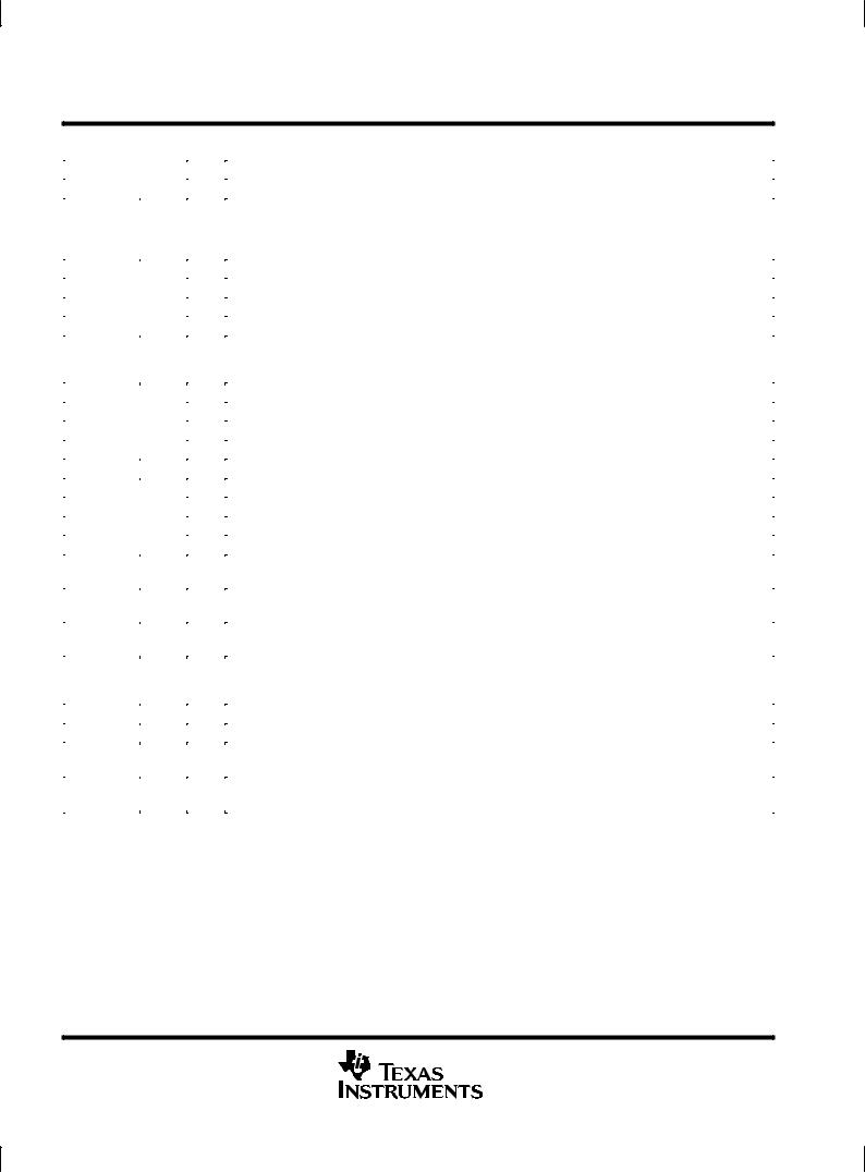
DB PACKAGE (TOP VIEW)
|
|
|
|
|
|
|
|
|
|
|
FLT |
|
1 |
24 |
|
|
VBAT |
||||
VCOMPEN |
|
2 |
23 |
|
|
N/C |
||||
|
|
|
||||||||
VCOMP |
|
3 |
22 |
|
|
RESET |
|
|||
|
|
|
|
|||||||
|
IN0 |
|
4 |
21 |
|
|
DRAIN0 |
|||
|
|
|
||||||||
|
IN1 |
|
5 |
20 |
|
|
GATE0 |
|||
|
|
|
||||||||
|
IN2 |
|
6 |
19 |
|
|
DRAIN1 |
|||
|
|
|
||||||||
|
IN3 |
|
7 |
18 |
|
|
GATE1 |
|||
|
|
|
||||||||
|
|
CS |
|
|
8 |
17 |
|
|
GATE2 |
|
|
|
|
|
|
|
|||||
SDO |
|
9 |
16 |
|
|
DRAIN2 |
||||
|
|
|
||||||||
|
SDI |
|
10 |
15 |
|
|
GATE3 |
|||
|
|
|
||||||||
SCLK |
|
11 |
14 |
|
|
DRAIN3 |
||||
|
|
|
||||||||
VCC |
|
12 |
13 |
|
|
GND |
||||
|
|
|
||||||||
|
|
|
||||||||
These devices provide control of output channels through a serial input interface or a parallel input interface. A command to enable the output from either interface enables the respective channels gate output to the external FET. The serial interface is recommended when the number of signals between the control device and the predriver must be minimized and the speed of operation is not critical. In applications where the predriver must respond very quickly or asynchronously, the parallel input interface is recommended.
For serial operation, the control device must transition CS from high to low to activate the serial input interface. When this occurs, SDO is enabled, fault data is latched into the serial interface, and the fault flag is refreshed.
Data is clocked into the serial registers on low-to-high transitions of SCLK through SDI. Each string of data must consist of at least four-bits of data. In applications where multiple devices are cascaded together, the string of data must consist of4 bits for each device. A high data bit turns the respective output channel on and a low data
Please be aware that an important notice concerning availability, standard warranty, and use in critical applications of Texas Instruments semiconductor products and disclaimers thereto appears at the end of this data sheet.
TI is a trademark of Texas Instruments Incorporated.
PRODUCTION DATA information is current as of publication date. Products conform to specifications per the terms of Texas Instruments standard warranty. Production processing does not necessarily include testing of all parameters.
Copyright 1997, Texas Instruments Incorporated
POST OFFICE BOX 655303 •DALLAS, TEXAS 75265 |
1 |

TPIC44L01, TPIC44L02, TPIC44L03
4-CHANNEL SERIAL AND PARALLEL LOW-SIDE PRE-FET DRIVER
SLIS062A ± NOVEMBER 1996 ± REVISED SEPTEMBER 1997
bit turns it off. Fault data for the device is clocked out of SDO as serial input data is clocked into the device. Fault data consists of fault flags for shorted-load and open-load flags (bits 0±3) for each of the four output channels. A high bit in the fault data indicates a fault and a low bit indicates that no fault is present for that channel. Fault register bits are set or cleared asynchronously to reflect the current state of the hardware. A fault must be present when CS is transitioned from high to low to be captured and reported in the serial fault data. New faults cannot be captured in the serial register when CS is low. CS must be transitioned high after all of the serial data has been clocked into the device. A low-to-high transition of CS transfers the last four bits of serial data to the output buffer puts SDO in a high-impedence state and clears and re-enables the fault register. The TPIC44L01/L02/L03 was designed to allow the serial input interfaces of multiple devices to be cascaded together to simplify the serial interface to the controller. Serial input data flows through the device and is transferred out SDO following the fault data in cascaded configurations.
For parallel operation, data is transferred directly from the parallel input interface IN0-IN3 to the respective GATE(0±3) output asynchronously. SCLK or CS is not required for parallel control. A 1 on the parallel input turns the respective channel on, where a 0 turns it off. Note that either the serial input interface or the parallel input interface can enable a channel. Under parallel operation, fault data must still be collected through the serial data interface.
The predrivers monitor the drain voltage for each channel to detect shorted-load or open-load fault conditions in the the on and off states respectively. These devices offer the option of using an internally generated fault-reference voltage or an externally supplied fault-reference voltage through VCOMP for fault detection. The internal fault reference is selected by connecting VCOMPEN to GND and the external reference is selected by connecting VCOMPEN to VCC. The drain voltage is compared to the fault reference when the channel is turned on to detect shorted-load conditions and when the channel is off to detect open-load conditions. When a shorted fault occurs using the TPIC44L01 or the TPIC44L03, the channel is turned off and a fault flag is sent to the control device as well as to the serial fault register bits. If a fault occurs while using the TPIC44L02, the channel transitions into a low-duty-cycle, pulse-width-modulated (PWM) signal as long as the fault is present.
Shorted-load fault conditions must be present for at least the shorted-load deglitch time, t(STBDG), to be flagged as a fault. A fault flag is sent to the control device as well as the serial fault register bits. More detail on fault
detection operation is presented in the device operation section of this data sheet.
These devices provide protection from over-battery voltage and under-battery voltage conditions irrespective of the state of the output channels. When the battery voltage is greater than the overvoltage threshold or less than the undervoltage threshold, all channels are disabled and a fault flag is generated. Battery-voltage faults are not reported in the serial fault data. The outputs return to normal operation once the battery-voltage fault has been corrected. When an over-battery/under-battery voltage condition occurs, the device reports the battery fault, but disables fault reporting for openand shorted-load conditions. Fault reporting for openand shorted-load conditions are re-enabled after the battery fault condition has been corrected.
These devices provide inductive transient protection on all channels. The drain voltage is clamped to protect the FET. The clamp voltage is defined by the sum of VC and turn-on voltage of the external FET. The predriver also provides a gate-to-source voltage (VGS) clamp to protect the gate-source terminals of the power FET from
exceeding their rated voltages. An external active low RESET is provided to clear all registers and flags in the device. GATE(0±3) outputs are disabled after RESET has been pulled low.
These devices provide pulldown resistors on all inputs except CS and RESET. A pullup resistor is used on CS and RESET.
2 |
POST OFFICE BOX 655303 •DALLAS, TEXAS 75265 |

TPIC44L01, TPIC44L02, TPIC44L03 4-CHANNEL SERIAL AND PARALLEL LOW-SIDE PRE-FET DRIVER
SLIS062A ± NOVEMBER 1996 ± REVISED SEPTEMBER 1997
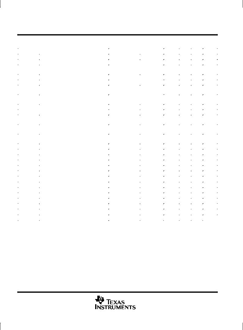
schematic diagram |
|
|
|
|
|
|
4 |
|
|
|
|
Fault Logic |
|
|
|
|
RST |
|
|
SDI |
|
Serial Register |
|
SDO |
SCLK |
|
|
||
|
|
|
|
|
VCC |
|
|
|
|
CS |
|
Parallel Register |
|
|
|
|
4 |
|
|
IN 0 |
|
RST |
|
|
|
|
|
PREZ |
|
IN 1 |
|
|
|
|
IN 2 |
|
|
GND |
D |
IN 3 |
|
|
|
Q |
|
|
|
|
RST |
|
|
|
|
DRAIN 0 |
|
|
4 |
|
DRAIN 1 |
|
|
|
DRAIN 2 |
|
|
|
|
|
|
|
|
|
|
DRAIN 3 |
|
|
STB and Open-Load Fault |
|
|
|
|
Protection |
OSC |
S |
|
|
|
||
|
|
|
|
|
|
2 |
|
BIAS |
B |
|
|
|
||
|
|
Gate |
|
A |
|
|
|
|
|
|
|
Drive Block |
Vbg |
|
|
OVLO² |
|
|
|
VBAT |
|
|
|
|
UVLO |
|
|
GATE 0 |
|
|
|
|
|
GATE 1 |
|
VCC |
|
|
GATE 2 |
|
|
|
GATE 3 |
|
|
|
RST |
|
|
RESET |
RST |
² OVLO not on TPIC44L03
FLT
VCOMPEN
VCOMP
POST OFFICE BOX 655303 •DALLAS, TEXAS 75265 |
3 |
TPIC44L01, TPIC44L02, TPIC44L03
4-CHANNEL SERIAL AND PARALLEL LOW-SIDE PRE-FET DRIVER
SLIS062A ± NOVEMBER 1996 ± REVISED SEPTEMBER 1997
|
|
|
|
|
|
|
|
|
Terminal Functions |
||||
|
|
|
|
|
|
|
|
|
|
|
|
|
|
|
|
|
TERMINAL |
I/O |
|
|
|
|
DESCRIPTION |
||||
|
|
NAME |
NO. |
|
|
|
|
||||||
|
|
|
|
|
|
|
|
|
|
||||
|
|
|
|
|
|
|
|
|
|
|
|
|
|
|
|
|
|
|
8 |
I |
Chip select. A high to low transition on |
|
enables SDO, latches fault data into the serial interface, and |
||||
|
CS |
|
|
|
CS |
||||||||
|
|
|
|
|
|
|
refreshes FLT. When CS is high, the fault registers can change fault status. On the falling edge of CS, fault data |
||||||
|
|
|
|
|
|
|
is latched into the serial output register and transferred using SDO and SCLK. On a low to high transition of |
||||||
|
|
|
|
|
|
|
CS, serial data is latched in to the output control register. |
||||||
|
|
|
|
|
|
|
|
|
|
|
|
|
|
|
DRAIN0 |
21 |
I |
|
|
|
|
|
|
|
|||
|
DRAIN1 |
19 |
|
FET drain inputs. DRAIN0 through DRAIN3 are used for both open-load and short-circuit fault detection at the |
|||||||||
|
DRAIN2 |
16 |
|
drain of the external FETs. They are also used for inductive transient protection. |
|||||||||
|
DRAIN3 |
14 |
|
|
|
|
|
|
|
|
|||
|
|
|
|
|
|
|
|
|
|
||||
|
|
|
|
|
1 |
I |
Fault flag. |
|
is a logic level open-drain output that provides a real-time fault flag for shorted-load/ |
||||
|
FLT |
|
|
FLT |
|||||||||
|
|
|
|
|
|
|
open-load/over-battery voltage/under-battery voltage faults. The device can be ORed with FLT terminals on |
||||||
|
|
|
|
|
|
|
other devices for interrupt handling. FLT requires an external pullup resistor. |
||||||
|
|
|
|
|
|
|
|
|
|
|
|
||
|
GATE0 |
20 |
O |
|
|
|
|
|
|
|
|||
|
GATE1 |
18 |
|
Gate drive output. GATE0 through GATE3 outputs are derived from the VBAT supply voltage. Internal clamps |
|||||||||
|
GATE2 |
17 |
|
prevent voltages on these nodes from exceeding the VGS rating on most FETs. |
|||||||||
|
GATE3 |
15 |
|
|
|
|
|
|
|
|
|||
|
|
|
|
|
|
|
|
||||||
|
GND |
13 |
I |
Ground and substrate |
|||||||||
|
|
|
|
|
|
|
|
|
|
|
|
||
|
IN0 |
4 |
I |
|
|
|
|
|
|
|
|||
|
IN1 |
5 |
|
Parallel gate driver. IN0 through IN3 are real-time controls for the gate predrive circuitry. They are CMOS |
|||||||||
|
IN2 |
6 |
|
compatible with hysteresis. |
|||||||||
|
IN3 |
7 |
|
|
|
|
|
|
|
|
|||
|
|
|
|
|
|
|
|||||||
|
|
|
|
|
22 |
I |
Reset. A high-to-low transition of RESET clears all registers and flags. Gate outputs turn off and the |
|
flag |
||||
|
RESET |
|
FLT |
||||||||||
|
|
|
|
|
|
|
is cleared. |
||||||
|
|
|
|
|
|||||||||
|
SCLK |
11 |
I |
Serial clock. SCLK clocks the shift register. Serial data is clocked into SDI and serial fault data is clocked out |
|||||||||
|
|
|
|
|
|
|
of SDO on the falling edge of the serial clock. |
||||||
|
|
|
|
|
|||||||||
|
SDI |
10 |
I |
Serial data input. Output control data is clocked into the serial register through SDI. A 1 on SDI commands a |
|||||||||
|
|
|
|
|
|
|
particular gate output on and a 0 turns it off. |
||||||
|
|
|
|
|
|||||||||
|
SDO |
9 |
O |
Serial data output. SDO is a 3-state output that transfers fault data to the controlling device. It also passes serial |
|||||||||
|
|
|
|
|
|
|
input data to the next stage for cascaded operation. SDO is taken to a high-impedance state when CS is in a |
||||||
|
|
|
|
|
|
|
high state. |
||||||
|
|
|
|
|
|||||||||
|
VBAT |
24 |
I |
Battery supply voltage |
|||||||||
|
VCC |
12 |
I |
Logic supply voltage |
|||||||||
|
VCOMPEN |
2 |
I |
Fault reference voltage select. VCOMPEN selects the internally generated fault reference voltage (0) or an |
|||||||||
|
|
|
|
|
|
|
external fault reference (1) to be used in the shortedand open-load fault detection circuitry. |
||||||
|
|
|
|
|
|||||||||
|
VCOMP |
3 |
I |
Fault reference voltage. VCOMP provides an external fault reference voltage for the shorted-load and |
|||||||||
|
|
|
|
|
|
|
open-load fault detection circuitry. |
||||||
|
|
|
|
|
|
|
|
|
|
|
|
|
|
4 |
POST OFFICE BOX 655303 •DALLAS, TEXAS 75265 |

TPIC44L01, TPIC44L02, TPIC44L03 4-CHANNEL SERIAL AND PARALLEL LOW-SIDE PRE-FET DRIVER
SLIS062A ± NOVEMBER 1996 ± REVISED SEPTEMBER 1997
absolute maximum ratings over operating free-air temperature range (unless otherwise noted)²
Supply voltage range, VCC (see Note 1) . . . . . . . . . . . . . . . . . . . . . . . . . . . . . . . . . . . . . . . . . . . |
. . . ±0.3 V to 7 V |
|||
Battery supply voltage range, VBAT . . . . . . . . . . . . . . . . . . . . . . . . . . . . . . . . . . . . . . . . . . . . . . . |
. . ±0.3 V to 60 V |
|||
Input voltage range,VI (at any input) . . . . . . . . . . . . . . . . . . . . . . . . . . . . . . . . . . . . . . . . . . . . . . . |
. . . ±0.3 V to 7 |
V |
||
Output voltage range, VO (SDO and |
FLT) |
. . . . . . . . . . . . . . . . . . . . . . . . . . . . . . . . . . . . . . . . . |
. . . ±0.3 V to 7 |
V |
Drain-to-source voltage, VDS . . . . . . . . . . . . . . . . . . . . . . . . . . . . . . . . . . . . . . . . . . . . . . . . . . . . |
. . ±0.3 V to 60 |
V |
||
Output voltage, VO . . . . . . . . . . . . . . . . . . . . . . . . . . . . . . . . . . . . . . . . . . . . . . . . . . . . . . . . . . . . . |
. . ±0.3 V to 15 |
V |
||
Operating case temperature range, TC . . . . . . . . . . . . . . . . . . . . . . . . . . . . . . . . . . . . . . . . . . . |
±40°C to + 125°C |
|||
Thermal resistance, junction to ambient, RθJA . . . . . . . . . . . . . . . . . . . . . . . . . . . . . . . . . . . . . . |
. . . . . . . 135°C/W |
|||
Maximum junction temperature, TJ . . . . . . . . . . . . . . . . . . . . . . . . . . . . . . . . . . . . . . . . . . . . . . . |
. . . . . . . . . 150°C |
|||
Storage temperature range, Tstg . . . . . . . . . . . . . . . . . . . . . . . . . . . . . . . . . . . . . . . . . . . . . . . . |
±40°C to + 150°C |
|||
²Stresses beyond those listed under ªabsolute maximum ratingsº may cause permanent damage to the device. These are stress ratings only, and functional operation of the device at these or any other conditions beyond those indicated under ªrecommended operating conditionsº is not implied. Exposure to absolute-maximum-rated conditions for extended periods may affect device reliability.
NOTE 1: All voltage values are with respect to GND.
recommended operating conditions
|
MIN |
NOM |
MAX |
UNIT |
|
|
|
|
|
Logic supply voltage, VCC |
4.5 |
5 |
5.5 |
V |
Battery supply voltage, VBAT |
8 |
|
24 |
V |
High-level input voltage, VIH |
0.85 VCC |
|
VCC |
V |
Low-level input voltage, VIL |
0 |
|
0.15 VCC |
V |
Setup time, SDI high before SCLK rising edge, tsu (see Figure 5) |
10 |
|
|
ns |
Hold time, SDI high after SCLK rising edge, th (see Figure 5) |
10 |
|
|
ns |
Case temperature, TC |
±40 |
|
125 |
°C |
POST OFFICE BOX 655303 •DALLAS, TEXAS 75265 |
5 |
TPIC44L01, TPIC44L02, TPIC44L03
4-CHANNEL SERIAL AND PARALLEL LOW-SIDE PRE-FET DRIVER
SLIS062A ± NOVEMBER 1996 ± REVISED SEPTEMBER 1997
electrical characteristics over recommended operating free-air temperature range (unless otherwise noted)
|
PARAMETER |
TEST CONDITIONS |
MIN |
TYP |
MAX |
UNIT |
||||
|
|
|
|
|
|
|
|
|
|
|
IBAT |
Supply current, VBAT |
All outputs off, |
VBAT = 12 V |
300 |
500 |
700 |
μA |
|||
ICC |
Supply current, VCC |
All outputs off, |
VBAT = 5.5 V |
1 |
2.6 |
4.2 |
mA |
|||
V(turnon) |
Turn-on voltage, logic operational, VCC |
Vbat = 5.5 V, |
|
2.6 |
3.5 |
4.4 |
V |
|||
Check output functionality |
||||||||||
|
|
|
|
|
|
|
|
|||
|
|
|
|
|
|
|
|
|
|
|
V(ovsd) |
Over-battery-voltage shutdown |
Gate disabled, |
See Figure 16 |
32 |
34 |
36 |
V |
|||
Vhys(ov) |
Over-battery-voltage reset hysteresis |
0.5 |
1 |
1.5 |
V |
|||||
|
|
|||||||||
V(uvsd) |
Under-battery-voltage shutdown, |
|
|
4.1 |
4.8 |
5.4 |
V |
|||
(TPIC44L01/L02 only) |
|
|
||||||||
|
Gate disabled, |
See Figure 17 |
|
|
|
|
||||
|
|
|
|
|
|
|
|
|||
Vhys(uv) |
Under-battery-voltage reset hysteresis, |
100 |
200 |
300 |
mV |
|||||
|
|
|||||||||
(TPIC44L01/L02 only) |
|
|
||||||||
|
|
|
|
|
|
|
||||
|
|
|
|
|
|
|
|
|
|
|
VG |
Gate drive voltage |
8 V < VBAT < 24, |
IO = 100 μA |
7 |
|
13.5 |
V |
|||
5.5 V < VBAT < 8 V, |
IO = 100 μA |
5 |
|
7 |
V |
|||||
|
|
|
|
|
||||||
IO(H) |
Maximum current output for drive terminals, |
VOUT = GND |
|
0.5 |
1.2 |
2.5 |
mA |
|||
pullup |
|
|||||||||
|
|
|
|
|
|
|
||||
|
|
|
|
|
|
|
|
|
|
|
IO(L) |
Maximum current output for drive terminals, |
VOUT = 7 V |
|
0.5 |
1.2 |
2.5 |
mA |
|||
pulldown |
|
|||||||||
|
|
|
|
|
|
|
||||
|
|
|
|
|
|
|
|
|
|
|
V(stb) |
Short-to-battery/shorted-load/open-load |
VCOMPEN = L |
|
1.1 |
1.25 |
1.4 |
V |
|||
detection voltage |
|
|||||||||
|
|
|
|
|
|
|
||||
|
|
|
|
|
|
|
|
|
|
|
Vhys(stb) |
Short-to-battery hysteresis |
|
|
40 |
100 |
150 |
mV |
|||
VD(open) |
Open-load off-state detection voltage threshold |
VCOMPEN = L |
|
1.1 |
1.25 |
1.4 |
V |
|||
Vhys(open) |
Open-load hysteresis |
|
|
40 |
100 |
150 |
mV |
|||
II(open) |
Open-load off-state detection current |
|
|
30 |
60 |
80 |
μA |
|||
II(PU) |
Input pullup current |
|
|
VCC = 5 V, |
VIN = 0 |
|
10 |
|
μA |
|
(CS) |
|
|
|
|||||||
II(PD) |
Input pulldown current |
VCC = 5 V, |
VIN = 5 V |
|
10 |
|
μA |
|||
Vhys |
Input voltage hysteresis |
VCC = 5 V |
|
0.6 |
0.85 |
1.1 |
V |
|||
VO(SH) |
High-level serial output voltage |
IO = 1 mA |
|
0.8 VCC |
|
|
V |
|||
VO(SL) |
Low-level serial output voltage |
IO = 1 mA |
|
|
0.1 |
0.4 |
V |
|||
IOZ(SD) |
3-state current serial-data output |
VCC = 0 to 5.5V |
|
-10 |
1 |
10 |
μA |
|||
VO(CFLT) |
Fault-interrupt output voltage |
IO = 1 mA |
|
|
0.1 |
0.5 |
V |
|||
VI(COMP) |
Fault-external reference voltage |
VCOMPEN = H |
|
1 |
|
3 |
V |
|||
VC |
Output clamp voltage, (TPIC44L01/L02 only) |
dc < 1%, |
tw = 100 μs |
47 |
55 |
63 |
V |
|||
VC |
Output clamp voltage, (TPIC44L03 only) |
dc < 1%, |
tw = 100 μs |
47 |
53.5 |
60 |
V |
|||
6 |
POST OFFICE BOX 655303 •DALLAS, TEXAS 75265 |
 Loading...