


Texas Instruments CD74HCT221M96, CD74HCT221M, CD74HCT221E, CD74HC221M96, CD74HC221M Datasheet
...Data sheet acquired from Harris Semiconductor SCHS166A
November 1997 - Revised April 1999
CD74HC221,
CD74HCT221
High Speed CMOS Logic Dual Monostable Multivibrator with Reset
|
Features |
Description |
|
|
|
|
|
|
|
|
|
|
||||||
|
• |
Overriding RESET Terminates Output Pulse |
The CD74HC221, and CH74HCT221 are dual monostable |
|||||||||||||||
[ /Title |
• |
Triggering from the Leading or Trailing Edge |
multivibrators with reset. An external resistor (RX) and an |
|||||||||||||||
external capacitor (CX) control the timing and the accuracy |
||||||||||||||||||
|
|
|
|
|
||||||||||||||
(CD74 |
• Q andQ Buffered Outputs |
|||||||||||||||||
for the circuit. Adjustment of RX and CX provides a wide |
||||||||||||||||||
HC221 |
• |
Separate Resets |
range of output pulse widths from the Q and |
Q |
terminals. |
|||||||||||||
, |
• |
Wide Range of Output-Pulse Widths |
Pulse triggering on the B input occurs at a particular voltage |
|||||||||||||||
level and is not related to the rise and fall time of the trigger |
||||||||||||||||||
CD74 |
• Schmitt Trigger on B Inputs |
|||||||||||||||||
pulse. |
|
|
|
|
|
|
|
|
|
|
||||||||
HCT22 |
• |
Fanout (Over Temperature Range) |
Once triggered, the outputs are independent of further trigger |
|||||||||||||||
1) |
|
- Standard Outputs . . . . . . . . . . . . . . . 10 LSTTL Loads |
||||||||||||||||
|
inputs on |
|
and B. The output pulse can be terminated by a |
|||||||||||||||
|
A |
|||||||||||||||||
/Sub- |
|
- Bus Driver Outputs . . . . . . . . . . . . . 15 LSTTL Loads |
LOW level on the Reset |
|
pin. Trailing Edge triggering |
|
|
|||||||||||
|
(R) |
(A) |
||||||||||||||||
ject |
• Wide Operating Temperature Range . . . -55oC to 125oC |
and leading-edge-triggering (B) inputs are provided for |
||||||||||||||||
(High |
• |
Balanced Propagation Delay and Transition Times |
triggering from either edge of the input pulse. On power up, |
|||||||||||||||
the IC is reset. If either Mono is not used each input (on the |
||||||||||||||||||
Speed |
|
|
|
|
||||||||||||||
• Significant Power Reduction Compared to LSTTL |
unused device) must be terminated either high or low. |
|||||||||||||||||
CMOS |
|
Logic ICs |
The minimum value of external resistance, RX, is typically 500Ω. |
|||||||||||||||
|
|
|
|
|||||||||||||||
Logic |
• HC Types |
The minimum value of external capacitance, CX, is 0pF. The |
||||||||||||||||
Dual |
|
- 2V to 6V Operation |
calculation for the pulse width is tW = 0.7 RXCX at VCC = 4.5V. |
|||||||||||||||
Monos |
|
- High Noise Immunity: NIL = 30%, NIH = 30% of VCC |
Ordering Information |
|
|
|
|
|
|
|||||||||
table |
|
at VCC = 5V |
|
|
|
|
|
|
||||||||||
|
|
|
|
|
|
|
|
|
|
|
|
|
|
|||||
Multi- |
• HCT Types |
|
|
|
TEMP. RANGE (oC) |
|
|
|
|
PKG. |
||||||||
|
|
- 4.5V to 5.5V Operation |
PART NUMBER |
|
PACKAGE |
|
NO. |
|||||||||||
|
|
- Direct LSTTL Input Logic Compatibility, |
CD74HC221E |
-55 to 125 |
|
16 Ld PDIP |
|
E16.3 |
||||||||||
|
|
VIL= 0.8V (Max), VIH = 2V (Min) |
|
|
|
|
|
|
||||||||||
|
|
CD74HCT221E |
-55 to 125 |
|
16 Ld PDIP |
|
E16.3 |
|||||||||||
|
|
- CMOS Input Compatibility, Il ≤ 1μA at VOL, VOH |
|
|
|
|
|
|
|
|
|
|
|
|
|
|||
|
|
CD74HC221M |
-55 to 125 |
|
16 Ld SOIC |
|
M16.15 |
|||||||||||
|
|
|
|
|
|
|
||||||||||||
|
|
|
|
|
|
|
|
|
|
|
||||||||
|
|
|
|
|
CD74HCT221M |
-55 to 125 |
|
16 Ld SOIC |
|
M16.15 |
||||||||
|
|
|
|
|
|
|
|
|
|
|
|
|
|
|
|
|||
|
|
|
|
|
NOTES: |
|
|
|
|
|
|
|
|
|
|
|||
|
|
|
|
|
1. When ordering, use the entire part number. Add the suffix 96 to |
|||||||||||||
|
|
|
|
|
obtain the variant in the tape and reel. |
|
|
|
|
|
|
|||||||
|
|
|
|
|
2. Wafer or die are available which meets all electrical |
|
|
|
|
|||||||||
|
|
|
|
|
specifications. Please contact your local sales office or Harris |
|||||||||||||
|
|
|
|
|
customer service for ordering information. |
|
|
|
|
|||||||||
Pinout
CD74HC221, CD74HCT221
(PDIP, SOIC)
TOP VIEW
1A |
1 |
16 VCC |
1B |
2 |
15 1CXRX |
1R |
3 |
14 1CX |
1Q |
4 |
13 1Q |
2Q |
5 |
12 |
2Q |
2CX |
6 |
11 |
2R |
2CXRX |
7 |
10 2B |
GND |
8 |
9 2A |
CAUTION: These devices are sensitive to electrostatic discharge. Users should follow proper IC Handling Procedures. |
File Number 1670.1 |
|
Copyright © Harris Corporation 1997
1
CD74HC221, CD74HCT221
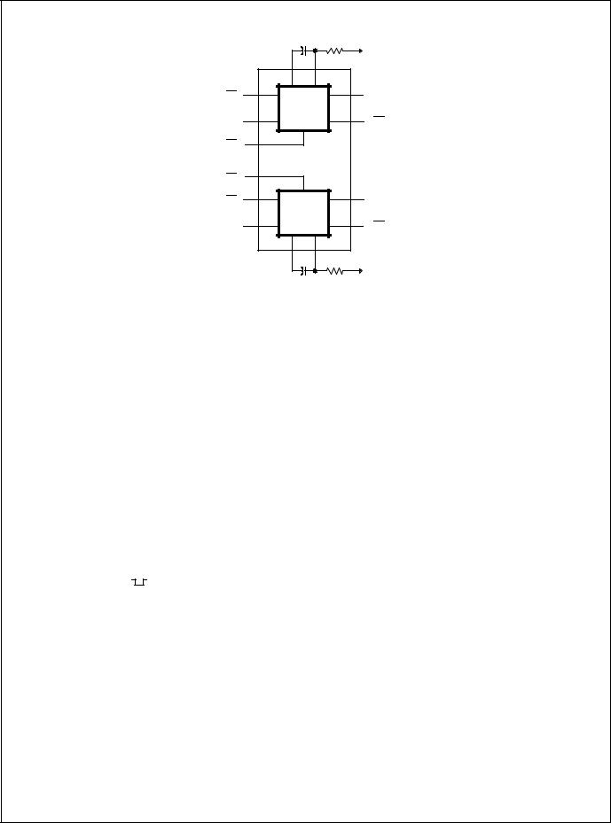
Functional Diagram
|
1CX |
1RX |
|
|
|
|
VCC |
|
14 |
15 |
|
|
1CX |
1CXRX |
13 |
|
|
|
|
1A |
|
|
1Q |
1 |
MONO 1 |
4 |
|
|
|||
|
|
|
|
1B |
|
|
1Q |
2 |
|
|
|
1R |
|
|
|
3 |
|
|
|
11 |
|
|
|
2R |
|
|
|
9 |
|
|
5 |
2A |
|
|
2Q |
10 |
MONO 2 |
12 |
|
|
|
||
2B |
|
|
2Q |
|
2CX |
2CXRX |
|
|
6 |
7 |
|
|
|
|
VCC |
|
2CX |
2RX |
|
TRUTH TABLE
|
|
|
INPUTS |
|
|
|
|
|
OUTPUTS |
|||||||||
|
|
|
|
|
|
|
|
|
|
|
|
|
|
|
|
|
|
|
|
|
|
B |
|
|
|
|
|
Q |
|
|
|
|
|
|
|
||
|
A |
R |
Q |
|||||||||||||||
|
|
|
|
|
|
|
|
|
|
|
|
|
|
|
|
|
||
|
H |
|
X |
|
H |
|
|
L |
|
|
|
H |
||||||
|
|
|
|
|
|
|
|
|
|
|
|
|
|
|
|
|
||
|
X |
|
L |
|
H |
|
|
L |
|
|
|
H |
||||||
|
|
|
|
|
|
|
|
|
|
|
|
|
|
|
|
|
|
|
|
L |
|
− |
|
H |
|
|
|
|
|
|
|
|
|
|
|
|
|
|
|
|
|
|
|
|
|
|
|
|
|
|
|
|
||||
|
|
|
|
|
|
|
|
|
|
|
|
|
|
|
|
|
|
|
|
|
|
|
|
|
|
|
|
|
|
|
|
|
|
|
|
|
|
|
↓ |
|
H |
|
H |
|
|
|
|
|
|
|
|
|
|
|
|
|
|
|
|
|
|
|
|
|
|
|
|
|
|
|
|
||||
|
|
|
|
|
|
|
|
|
|
|
|
|
|
|
|
|
||
|
|
|
|
|
|
|
|
|
|
|
|
|
|
|
|
|
|
|
|
X |
|
X |
|
L |
|
|
L |
|
|
|
H |
||||||
|
|
|
|
|
|
|
|
|
|
|
|
|
|
|
|
|
|
|
|
L |
|
H |
|
− |
|
|
|
|
|
|
|
|
|
|
|
|
|
|
|
|
|
|
|
|
|
|
|
|
|
|
|
|
||||
|
|
|
|
|
|
|
|
|
|
|
|
|
|
|
||||
|
|
|
|
|
|
|
(Note 3) |
(Note 3) |
||||||||||
|
|
|
|
|
|
|
|
|
|
|
|
|
|
|
|
|
|
|
NOTE:
H = High Voltage Level, L = Low Voltage Level, X = Irrelevant, − = Transition from Low to High Level, ↓ = Transition from High to Low Level, 
 = One High Level Pulse,
= One Low Level Pulse
3.For this combination the reset input must be low and the following sequence must be used: pin 1 (or 9) must be set high or pin 2 (or 10) set low; then pin 1 (or 9) must be low and pin 2 (or 10) set high. Now the reset input goes from low-to-high and the device will be triggered.
2

|
|
CD74HC221, CD74HCT221 |
|
|
||||
Logic Diagram |
|
|
|
|
|
|
VCC |
|
|
|
|
|
|
|
|
|
|
|
|
C |
P |
|
|
|
16 |
|
|
|
|
|
|
|
|||
|
|
|
|
|
|
|
||
|
|
N |
|
|
|
|
|
RX |
A |
B |
R |
|
|
|
|
|
|
1 (9) |
2 (10) |
3 (11) |
|
|
|
|
|
|
|
|
|
|
|
|
VCC |
|
P |
|
|
|
|
|
|
P |
|
|
|
|
|
|
|
|
R |
R2 |
|
|
|
|
|
|
|
OP |
||
|
|
|
|
|
|
D |
|
|
|
|
|
RESET |
|
AMP |
15 (7) |
||
|
|
|
|
|
||||
|
|
|
|
C |
- |
|||
|
|
|
FF |
|
|
+ |
|
|
|
|
|
|
|
Q |
C |
|
RXCX |
S |
R |
|
VCC |
|
|
|
||
|
|
|
|
|
|
|||
|
|
|
|
MIRROR VOLTAGE |
|
R3 |
||
QM |
QM |
|
P P |
|
|
|
|
CX |
|
|
|
|
|
|
|
|
|
MASK |
R |
R1 |
|
|
|
|
|
|
FF |
S |
MAIN |
|
|
|
|
|
|
|
|
|
|
|
|
|
|
|
|
|
FF |
|
|
|
|
R4 |
|
|
|
|
|
|
|
|
|
|
|
Q |
Q |
|
|
|
|
|
|
|
|
|
N |
PULLDOWN |
|
14 (6) |
||
|
|
|
VCC |
FF |
|
|
CX |
|
|
|
|
|
|
|
|
||
|
|
|
|
D |
|
Q |
|
N |
|
|
|
|
|
|
|
|
8 |
|
|
|
|
C |
|
|
|
GND |
|
4 (12) |
(13) 5 |
|
C |
R |
Q |
|
|
|
|
|
|
|
|
|||
|
Q |
Q |
|
|
|
|
|
|
|
|
|
|
|
|
+ |
|
|
|
|
|
|
|
|
- |
|
|
|
|
|
|
|
|
|
OP AMP |
|
|
|
|
3 |
|
|
|
|
|
CD74HC221, CD74HCT221
Absolute Maximum Ratings |
|
Thermal Information |
|
|
|||
DC Supply Voltage, VCC . . |
. . |
. . . . . . . . . . . . . . . . . . . . |
-0.5V to 7V |
Thermal Resistance (Typical, Note 4) |
θJA (oC/W) θJC (oC/W) |
||
DC Input Diode Current, IIK |
|
|
±20mA |
PDIP Package . . . . . . . . . . . . . . . . . . . |
100 |
N/A |
|
For VI < -0.5V or VI > VCC + 0.5V . . . . . . . . . . . . . . . . . . |
SOIC Package . . . . . . . . . . . . . . . . . . . |
180 |
N/A |
||||
DC Output Diode Current, IOK |
|
|
Maximum Junction Temperature (Plastic Package) . |
. . . . . . . 150oC |
|||
For V |
< -0.5V or V > V |
CC |
+ 0.5V . . . . . . . . . . . . . . . . |
. . . .±20mA |
Maximum Storage Temperature Range . . |
. . . . . . . . |
-65oC to 150oC |
O |
O |
|
|
|
|
300oC |
|
DC Drain Current, per Output, IO |
±25mA |
Maximum Lead Temperature (Soldering 10s) . . . . . . |
|||||
For -0.5V < VO < VCC + 0.5V. . . . . . . . . . . . . . . . . . . . . . |
(SOIC - Lead Tips Only) |
|
|
||||
DC Output Source or Sink Current per Output Pin, IO |
±25mA |
|
|
|
|||
For VO > -0.5V or VO < VCC + 0.5V . . . . . . . . . . . . . . . . |
|
|
|
||||
DC VCC or Ground Current, ICC . . . . . . . . . . . . . . . . . . . . . |
. . . .±50mA |
|
|
|
|||
Operating Conditions
Temperature Range, TA . . . . . . . . . . . . . . . . . . . . . . -55oC to 125oC
Supply Voltage Range, VCC
HC Types . . . . . . . . . . . . . . . . . . . . . . . . . . . . . . . . . . . . .2V to 6V
HCT Types . . . . . . . . . . . . . . . . . . . . . . . . . . . . . . . . .4.5V to 5.5V
DC Input or Output Voltage, VI, VO . . . . . . . . . . . . . . . . . 0V to VCC
Input Rise and Fall Time, tr, tf on Inputs A and R
2V . . . . . . . . . . . . . . . . . . . . . . . . . . . . . . . . . . . . . . 1000ns (Max) 4.5V. . . . . . . . . . . . . . . . . . . . . . . . . . . . . . . . . . . . . . 500ns (Max)
6V . . . . . . . . . . . . . . . . . . . . . . . . . . . . . . . . . . . . . . . 400ns (Max) Input Rise and Fall Time, tr, tf on Input B
2V . . . . . . . . . . . . . . . . . . . . . . . . . . . . . . . . . . Unlimited ns (Max) 4.5V. . . . . . . . . . . . . . . . . . . . . . . . . . . . . . . . . Unlimited ns (Max) 6V . . . . . . . . . . . . . . . . . . . . . . . . . . . . . . . . . . Unlimited ns (Max)
CAUTION: Stresses above those listed in “Absolute Maximum Ratings” may cause permanent damage to the device. This is a stress only rating and operation of the device at these or any other conditions above those indicated in the operational sections of this specification is not implied.
NOTE:
4. θJA is measured with the component mounted on an evaluation PC board in free air.
DC Electrical Specifications
|
|
TEST |
|
|
25oC |
|
-40oC TO 85oC |
-55oC TO 125oC |
|
|||
|
|
CONDITIONS |
VCC |
|
|
|
||||||
PARAMETER |
SYMBOL |
VI (V) |
IO (mA) |
(V) |
MIN |
TYP |
MAX |
MIN |
MAX |
MIN |
MAX |
UNITS |
HC TYPES |
|
|
|
|
|
|
|
|
|
|
|
|
|
|
|
|
|
|
|
|
|
|
|
|
|
High Level Input |
VIH |
- |
- |
2 |
1.5 |
- |
- |
1.5 |
- |
1.5 |
- |
V |
Voltage |
|
|
|
|
|
|
|
|
|
|
|
|
|
|
|
4.5 |
3.15 |
- |
- |
3.15 |
- |
3.15 |
- |
V |
|
|
|
|
|
|||||||||
|
|
|
|
|
|
|
|
|
|
|
|
|
|
|
|
|
6 |
4.2 |
- |
- |
4.2 |
- |
4.2 |
- |
V |
|
|
|
|
|
|
|
|
|
|
|
|
|
Low Level Input |
VIL |
- |
- |
2 |
- |
- |
0.5 |
- |
0.5 |
- |
0.5 |
V |
Voltage |
|
|
|
|
|
|
|
|
|
|
|
|
|
|
|
4.5 |
- |
- |
1.35 |
- |
1.35 |
- |
1.35 |
V |
|
|
|
|
|
|||||||||
|
|
|
|
|
|
|
|
|
|
|
|
|
|
|
|
|
6 |
- |
- |
1.8 |
- |
1.8 |
- |
1.8 |
V |
|
|
|
|
|
|
|
|
|
|
|
|
|
High Level Output |
VOH |
VIH or VIL |
-0.02 |
2 |
1.9 |
- |
- |
1.9 |
- |
1.9 |
- |
V |
Voltage |
|
|
|
|
|
|
|
|
|
|
|
|
|
|
-0.02 |
4.5 |
4.4 |
- |
- |
4.4 |
- |
4.4 |
- |
V |
|
CMOS Loads |
|
|
||||||||||
|
|
|
|
|
|
|
|
|
|
|
|
|
|
|
-0.02 |
6 |
5.9 |
- |
- |
5.9 |
- |
5.9 |
- |
V |
|
|
|
|
||||||||||
|
|
|
|
|
|
|
|
|
|
|
|
|
High Level Output |
|
|
- |
- |
- |
- |
- |
- |
- |
- |
- |
V |
Voltage |
|
|
|
|
|
|
|
|
|
|
|
|
|
|
-4 |
4.5 |
3.98 |
- |
- |
3.84 |
- |
3.7 |
- |
V |
|
TTL Loads |
|
|
||||||||||
|
|
|
|
|
|
|
|
|
|
|
|
|
|
|
-5.2 |
6 |
5.48 |
- |
- |
5.34 |
- |
5.2 |
- |
V |
|
|
|
|
||||||||||
|
|
|
|
|
|
|
|
|
|
|
|
|
Low Level Output |
VOL |
VIH or VIL |
0.02 |
2 |
- |
- |
0.1 |
- |
0.1 |
- |
0.1 |
V |
Voltage |
|
|
|
|
|
|
|
|
|
|
|
|
|
|
0.02 |
4.5 |
- |
- |
0.1 |
- |
0.1 |
- |
0.1 |
V |
|
CMOS Loads |
|
|
||||||||||
|
|
|
|
|
|
|
|
|
|
|
|
|
|
|
0.02 |
6 |
- |
- |
0.1 |
- |
0.1 |
- |
0.1 |
V |
|
|
|
|
||||||||||
|
|
|
|
|
|
|
|
|
|
|
|
|
Low Level Output |
|
|
- |
- |
- |
- |
- |
- |
- |
- |
- |
V |
Voltage |
|
|
|
|
|
|
|
|
|
|
|
|
|
|
4 |
4.5 |
- |
- |
0.26 |
- |
0.33 |
- |
0.4 |
V |
|
TTL Loads |
|
|
||||||||||
|
|
|
|
|
|
|
|
|
|
|
|
|
|
|
5.2 |
6 |
- |
- |
0.26 |
- |
0.33 |
- |
0.4 |
V |
|
|
|
|
||||||||||
|
|
|
|
|
|
|
|
|
|
|
|
|
4
 Loading...