


1734-VHSC24
Table of contents
 Loading...
Installation Instructions
POINT I/O 5V DC and 24V DC Very High
Speed Counter Module
Catalog Numbers 1734-VHSC5, 1734-VHSC24, Series C
Table of Contents
Topic Page
Important User Information 2
Environment and Enclosure 3
Preventing Electrostatic Discharge 3
North American Hazardous Location Approval 4
European Hazardous Location Approval 5
Additional Resources 6
About the Module 6
Install the Mounting Base 8
Install the Module 8
Install the Removable Terminal Block 10
Remove a Mounting Base 11
Wire the Module 12
Communicate with Your Module 13
Interpret Status Indicators 20
Specifications 22
2 POINT I/O 5V DC and 24V DC Very High Speed Counter Module
Important User Information
Solid-state equipment has operational characteristics differing from those of electromechanical
equipment. Safety Guidelines for the Application, Installation and Maintenance of Solid State Controls
(Publication SGI-1.1
http://www.rockwellautomation.com/literature/
solid-state equipment and hard-wired electromechanical devices. Because of this difference, and also
because of the wide variety of uses for solid-state equipment, all persons responsible for applying this
equipment must satisfy themselves that each intended application of this equipment is acceptable.
In no event will Rockwell Automation, Inc. be responsible or liable for indirect or consequential damages
resulting from the use or application of this equipment.
The examples and diagrams in this manual are included solely for illustrative purposes. Because of the
many variables and requirements associated with any particular installation, Rockwell Automation, Inc.
cannot assume responsibility or liability for actual use based on the examples and diagrams.
No patent liability is assumed by Rockwell Automation, Inc. with respect to use of information, circuits,
equipment, or software described in this manual.
Reproduction of the contents of this manual, in whole or in part, without written permission of Rockwell
Automation, Inc., is prohibited.
Throughout this manual, when necessary, we use notes to make you aware of safety considerations.
available from your local Rockwell Automation sales office or online at
WARNING: Identifies information about practices or circumstances that can cause an
explosion in a hazardous environment, which may lead to personal injury or death,
property damage, or economic loss.
ATTENTION: Identifies information about practices or circumstances that can lead to
personal injury or death, property damage, or economic loss. Attentions help you
identify a hazard, avoid a hazard and recognize the consequences.
) describes some important differences between
SHOCK HAZARD: Labels may be on or inside the equipment (for example, drive or
motor) to alert people that dangerous voltage may be present.
BURN HAZARD: Labels may be on or inside the equipment (for example, drive or
motor) to alert people that surfaces may reach dangerous temperatures.
IMPORTANT Identifies information that is critical for successful application and understanding of
the product.
Publication 1734-IN003F-EN-E - January 2014
POINT I/O 5V DC and 24V DC Very High Speed Counter Module 3
Environment and Enclosure
ATTENTION: This equipment is intended for use in a Pollution Degree 2
industrial environment, in overvoltage Category II applications (as defined in IEC
60664-1), at altitudes up to 2000 m (6562 ft) without derating.
This equipment is not intended for use in residential environments and may not
provide adequate protection to radio communication services in such
environments.
This equipment is supplied as open-type equipment. It must be mounted within
an enclosure that is suitably designed for those specific environmental
conditions that will be present and appropriately designed to prevent personal
injury resulting from accessibility to live parts. The enclosure must have suitable
flame-retardant properties to prevent or minimize the spread of flame,
complying with a flame spread rating of 5VA or be approved for the application
if nonmetallic. The interior of the enclosure must be accessible only by the use
of a tool. Subsequent sections of this publication may contain additional
information regarding specific enclosure type ratings that are required to
comply with certain product safety certifications.
In addition to this publication, see:
• Industrial Automation Wiring and Grounding Guidelines, publication
1770-4.1
• NEMA Standard 250 and IEC 60529, as applicable, for explanations of the
, for additional installation requirements.
degrees of protection provided by enclosures.
Preventing Electrostatic Discharge
ATTENTION: This equipment is sensitive to electrostatic discharge, which can
cause internal damage and affect normal operation. Follow these guidelines
when you handle this equipment:
• Touch a grounded object to discharge potential static.
• Wear an approved grounding wriststrap.
• Do not touch connectors or pins on component boards.
• Do not touch circuit components inside the equipment.
• Use a static-safe workstation, if available.
• Store the equipment in appropriate static-safe packaging when not in use.
Publication 1734-IN003F-EN-E - January 2014
4 POINT I/O 5V DC and 24V DC Very High Speed Counter Module
North American Hazardous Location Approval
The following information applies when
operating this equipment in hazardous
locations:
Products marked "CL I, DIV 2, GP A, B, C, D" are suitable
for use in Class I Division 2 Group s A, B, C, D, Hazardous
Locations and nonhazardous locations only. Each product
is supplied with markings on the rat ing nameplate
indicating the hazardous location tempe rature code.
When combining products within a system, the most
adverse temperature code (lowest "T" number) may be
used to help determine the overall temperature code of
the system. Combinations of equipment in you r system
are subject to investigation by the local Authority Having
Jurisdiction at the time of installation.
EXPLOSION HAZARD
• Do not disconnect equipment unless
power has been removed or the area is
known to be nonhazardous.
• Do not disconnect connections to this
equipment unless power has been
removed or the area is known to be
nonhazardous. Secure any external
connections that mate to this equipment
by using screws, sliding latches,
threaded connectors, or other means
provided with this product.
• Substitution of components may impair
suitability for Class I, Division 2.
• If this product contains batteries, they
must only be changed in an area known
to be nonhazardous.
ATTENTION: To comply with UL restrictions, the secondary circuit (backplane)
must be powered from a source compliant with the following:
Class 2 or Limited Voltage/Current.
Informations sur l'utilisation de cet équipement
en environnements dangereux:
Les produits marqués "CL I, DIV 2, GP A, B, C, D" n e conviennent
qu'à une utilisation en environnements de Classe I Division 2
Groupes A, B, C, D dangereux et non dangereu x. Chaque produit
est livré avec des marquages sur sa plaque d'identification qui
indiquent le code de température pour les environnements
dangereux. Lorsque plusieurs produits sont combin és dans un
système, le code de température le plus défavorable (code de
température le plus faible) peut être utilisé pour déterminer le
code de température global du système. Les combinaisons
d'équipements dans le système sont sujettes à inspection par
les autorités locales qualifiées au moment de l'installation.
RISQUE D’EXPLOSION
• Couper le courant ou s'assurer que
l'environnement est classé non dangere ux
avant de débrancher l'équipement.
• Couper le courant ou s'assurer que
l'environnement est classé non dangere ux
avant de débrancher les connecteurs. Fixer
tous les connecteurs externes reliés à cet
équipement à l'aide de vis, loquets
coulissants, connecteurs filetés ou autres
moyens fournis avec ce produit.
• La substitution de composants peut rendre cet
équipement inadapté à une utilisation en
environnement de Classe I, Division 2.
• S'assurer que l'environnement est classé non
dangereux avant de changer les piles.
WARNING: If you insert or remove the module while backplane power is on,
an electrical arc can occur. This could cause an explosion in hazardous
location installations.
Be sure that power is removed or the area is nonhazardous
before proceeding.
Publication 1734-IN003F-EN-E - January 2014
POINT I/O 5V DC and 24V DC Very High Speed Counter Module 5
European Hazardous Location Approval
European Zone 2 Certification. The following applies when the product bears the
Ex Marking.
ATTENTION: This equipment is intended for use in potentially explosive atmospheres as
defined by European Union Directive 94/9/EC.
DEMKO certifies that this equipment has been found to comply with the Essential Health
and Safety Requirements relating to the design and construction of Category 3 equipment
intended for use in Zone 2 potentially explosive atmospheres, given in Annex II to
this Directive.
Compliance with the Essential Health and Safety Requirements has been assured by
compliance with EN 60079-15.
ATTENTION: This equipment is not resistant to sunlight or other sources of
UV radiation.
WARNING: This equipment shall be mounted in an ATEX certified enclosure
with a minimum ingress protection rating of at least IP54 ( as defined in
IEC60529) and used in an environment of not more than Pollution Degree 2 (as
defined in IEC 60664-1) when applied in Zone 2 environments. The enclosure
must utilize a tool removable cover or door.
WARNING: This equipment shall be used within its specified ratings defined
by Rockwell Automation.
WARNING: Provision shall be made to prevent the rated voltage from being
exceeded by transient disturbances of more than 140% of the rated voltage
when applied in Zone 2 environments.
WARNING: Secure any external connections that mate to this equipment by
using screws, sliding latches, threaded connectors, or other means provided
with this product.
WARNING: Do not disconnect equipment unless power has been removed or
the area is known to be nonhazardous.
Publication 1734-IN003F-EN-E - January 2014
6 POINT I/O 5V DC and 24V DC Very High Speed Counter Module
1
2
3
4
5
6
8
9
10
7
The wiring base assembly includes terminal base, 1734-TB or 1734-TBS, which consists
of mounting base, 1734-MB, and removable terminal base, 1734-RT or 1734-RTB.
Additional Resources
Refer to the POINT™ I/O Very High-Speed Counter Module User Manual, publication
1734-UM003
You can view or download publications at
, for more information on how to use the module.
http://www.rockwellautomation.com/literature/. To order paper copies of technical
documentation, contact your local Rockwell Automation distributor or sales
representative.
About the Module
You can use these Series C modules with DeviceNet and PROFIBUS adapters. If you are
using RSLogix 5000 software, version 11 or higher, you can also use the Series C modules
with ControlNet and Ethernet adapters.
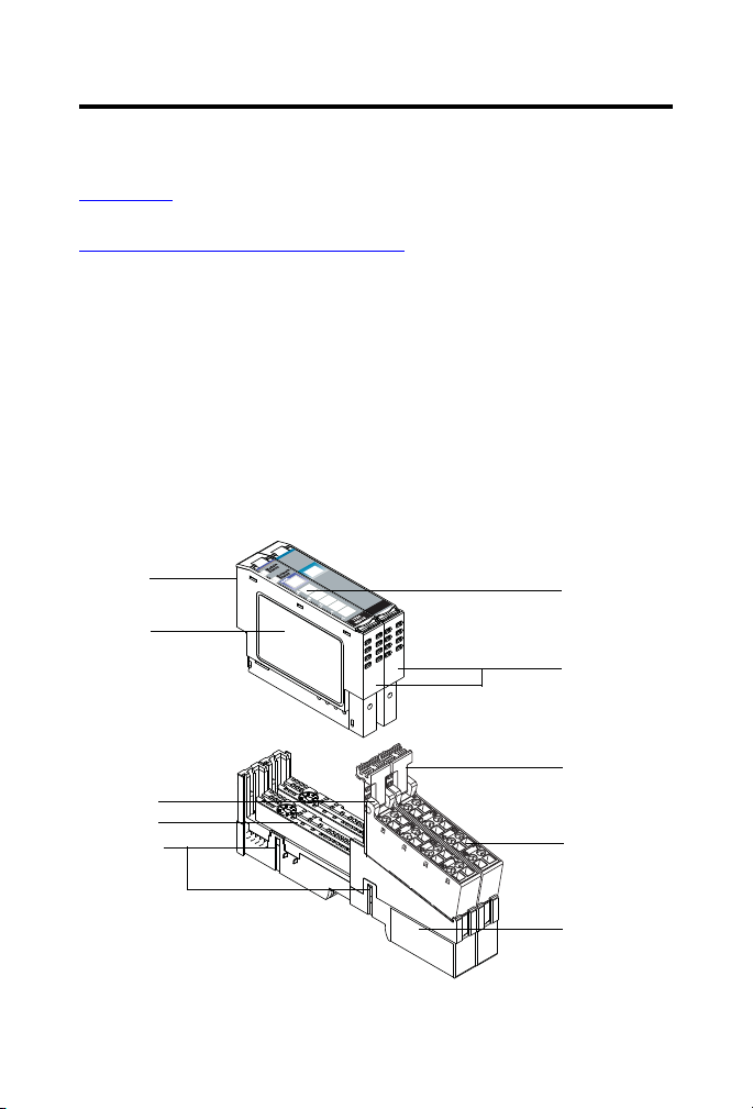
Use this diagram to identify the external features of the module. The 1734-VHSC5
module is shown here.
POINT I/O 5V DC and 24V DC Very High Speed Counter Module
NODE:
0
1
0
1
Publication 1734-IN003F-EN-E - January 2014

POINT I/O 5V DC and 24V DC Very High Speed Counter Module 7
Module Description
Description Description
1 Module locking mechanism 6 Slide-in writable label
2 Module locking mechanism 7 Insertable I/O module
3 DIN rail locking screw (orange) 8 Removable terminal block handle
4 Mechanical keying (orange) 9 Removable terminal block (RTB)
5 Interlocking side pieces 10 Mounting base
Before You Begin
The modules referred to in this publication are as follows:
• 1734-VHSC5, Series C
POINT I/O 5V DC Very High Speed Counter Module
• 1734-VHSC24, Series C
POINT I/O 24V D C Very High Speed Counter Module
The VHSC is a two-module set:
• Module 1 houses the VHSC functionality.
• Module 2 provides screw terminals necessary to access chassis ground (chas gnd)
and common (C).
– Module 2 connects screws 4 and 5 and screws 6 and 7 for ease of wiring
power to the input device.
– Module 2 is not necessary for VHSC functionality.
– Module 2 serves only to ease customer wiring.
– Module 2 does not use a node address or consume power from the
POINTBus.
Mount module 2 adjacent to module 1.
Publication 1734-IN003F-EN-E - January 2014

8 POINT I/O 5V DC and 24V DC Very High Speed Counter Module
Install the Mounting Base
To install the mounting base on the DIN rail, proceed as follows:
ATTENTION: This product is grounded through the DIN rail to chassis ground.
Use zinc plated yellow-chromate steel DIN rail to assure proper grounding. The
use of other DIN rail materials (for example, aluminum or plastic) that can
corrode, oxidize, or are poor conductors, can result in improper or intermittent
grounding. Secure DIN rail to mounting surface approximately every 200 mm
(7.8 in.) and use end-anchors appropriately.
1. Position the mounting base vertically above the installed units (adapter, power
supply or existing module).
2. Slide the mounting base down allowing the interlocking side pieces to engage the
adjacent module or adapter.
3. Press firmly to seat the mounting base on the DIN rail. The mounting base snaps
into place.
ATTENTION: Do not discard the end cap. Use this end cap to cover the exposed
interconnections on the last mounting base on the DIN rail. Failure to do so
could result in equipment damage or injury from electric shock.
Install the Module
ATTENTION: When you insert or remove the module while backplane power is
on, an electrical arc can occur. This could cause an explosion in hazardous
location installations.
Be sure that power is removed or the area is nonhazardous before proceeding.
Repeated electrical arcing causes excessive wear to contacts on both the
module and its mating connector. Worn contacts may create electrical
resistance that can affect module operation.
The module can be installed before or after base installation. Make sure that the mounting
base is correctly keyed before installing the module into the mounting base. In addition,
make sure the mounting base locking screw is positioned horizontal referenced to the base.
Publication 1734-IN003F-EN-E - January 2014
POINT I/O 5V DC and 24V DC Very High Speed Counter Module 9
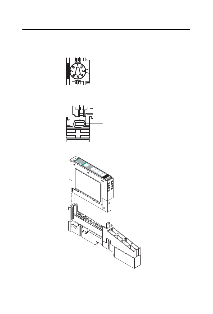
Turn the keyswitch to align the number
with the notch (position 3 is shown).
44009
Be sure the DIN rail locking screw is
in the horizontal position.
44010
24VDC
S
ource
O
utput
M
odule
Status
Netw
ork
Status
1
734
O
B
4E
NOD
E:
0
1
2
3
1. Using a bladed screwdriver, rotate the keyswitch on the mounting base clockwise
until the number required for the type of module being installed aligns with the
notch in the base.
2. Make certain the DIN rail locking screw is in the horizontal position. You cannot
insert the module if the locking mechanism is unlocked.
3. Insert the module straight down into the mounting base.
4. Press to secure. The module locks into place.
Publication 1734-IN003F-EN-E - January 2014
Loading...