


1756-IF4FXOF2F
Table of contents
 Loading...
User Manual
ControlLogix High-speed Analog I/O Module
Catalog Number 1756-IF4FXOF2F
Important User Information
IMPORTANT
Solid-state equipment has operational characteristics differing from those of electromechanical equipment. Safety
Guidelines for the Application, Installation and Maintenance of Solid State Controls (publication SGI-1.1
your local Rockwell Automation sales office or online at http://www.rockwellautomation.com/literature/
important differences between solid-state equipment and hard-wired electromechanical devices. Because of this difference,
and also because of the wide variety of uses for solid-state equipment, all persons responsible for applying this equipment
must satisfy themselves that each intended application of this equipment is acceptable.
In no event will Rockwell Automation, Inc. be responsible or liable for indirect or consequential damages resulting from the
use or application of this equipment.
The examples and diagrams in this manual are included solely for illustrative purposes. Because of the many variables and
requirements associated with any particular installation, Rockwell Automation, Inc. cannot assume responsibility or
liability for actual use based on the examples and diagrams.
No patent liability is assumed by Rockwell Automation, Inc. with respect to use of information, circuits, equipment, or
software described in this manual.
Reproduction of the contents of this manual, in whole or in part, without written permission of Rockwell Automation,
Inc., is prohibited.
Throughout this manual, when necessary, we use notes to make you aware of safety considerations.
available from
) describes some
WARNING: Identifies information about practices or circumstances that can cause an explosion in a hazardous environment,
which may lead to personal injury or death, property damage, or economic loss.
ATTENTION: Identifies information about practices or circumstances that can lead to personal injury or death, property
damage, or economic loss. Attentions help you identify a hazard, avoid a hazard, and recognize the consequence.
SHOCK HAZARD: Labels may be on or inside the equipment, for example, a drive or motor, to alert people that dangerous
voltage may be present.
BURN HAZARD: Labels may be on or inside the equipment, for example, a drive or motor, to alert people that surfaces may
reach dangerous temperatures.
Identifies information that is critical for successful application and understanding of the product.
Allen-Bradley, ControlFLASH, ControlLogix, ControlLogix-XT, Logix5000, Rockwell Software, Rockwell Automation, RSLogix, RSNetWorx, Studio 5000, and TechConnect are trademarks o f Rockwell Automation, Inc.
Trademarks not belonging to Rockwell Automation are property of their respective companies.

Summary of Changes
This manual contains new and updated information. Changes throughout this
revision are marked by change bars, as shown to the right of this paragraph.
New and Updated Information
This table contains the changes made to this revision.
Top ic Pag e
Studio 5000™ Logix Designer application is the rebranding of RSLogix™ 5000 software 9
Archiving 38
Archiving Connection communication format 75
Data storage 101
Archiving tags 117
Module revision history 143
Rockwell Automation Publication 1756-UM005B-EN-P - January 2013 3

Summary of Changes
Notes:
4 Rockwell Automation Publication 1756-UM005B-EN-P - January 2013

Table of Contents
Preface
What is the ControlLogix
High-speed Analog I/O Module?
High-speed Analog I/O Operation
in the ControlLogix System
Module Features
Studio 5000 Environment . . . . . . . . . . . . . . . . . . . . . . . . . . . . . . . . . . . . . . . . . . 9
Additional Resources . . . . . . . . . . . . . . . . . . . . . . . . . . . . . . . . . . . . . . . . . . . . . 10
Chapter 1
Available Features . . . . . . . . . . . . . . . . . . . . . . . . . . . . . . . . . . . . . . . . . . . . . . . . 11
High-speed Analog I/O Modules in the ControlLogix System . . . . . . . 12
Chapter 2
Ownership and Connections. . . . . . . . . . . . . . . . . . . . . . . . . . . . . . . . . . . . . . 16
Configure the Module. . . . . . . . . . . . . . . . . . . . . . . . . . . . . . . . . . . . . . . . . . . . 16
Direct Connections . . . . . . . . . . . . . . . . . . . . . . . . . . . . . . . . . . . . . . . . . . . . . . 17
Inputs and Outputs on the Same Module . . . . . . . . . . . . . . . . . . . . . . . . . . 18
Real Time Sample (RTS). . . . . . . . . . . . . . . . . . . . . . . . . . . . . . . . . . . . . . 18
Requested Packet Interval (RPI) . . . . . . . . . . . . . . . . . . . . . . . . . . . . . . . 19
Differences between Inputs and Outputs. . . . . . . . . . . . . . . . . . . . . . . . . . . 20
Module Input Operation. . . . . . . . . . . . . . . . . . . . . . . . . . . . . . . . . . . . . . 20
Module Output Operation. . . . . . . . . . . . . . . . . . . . . . . . . . . . . . . . . . . . 21
Listen-only Mode . . . . . . . . . . . . . . . . . . . . . . . . . . . . . . . . . . . . . . . . . . . . . . . . 22
Chapter 3
Input Compatibility. . . . . . . . . . . . . . . . . . . . . . . . . . . . . . . . . . . . . . . . . . . . . . 23
Output Compatibility . . . . . . . . . . . . . . . . . . . . . . . . . . . . . . . . . . . . . . . . . . . . 23
General Module Features . . . . . . . . . . . . . . . . . . . . . . . . . . . . . . . . . . . . . . . . . 24
Removal and Insertion Under Power (RIUP) . . . . . . . . . . . . . . . . . . . 24
Module Fault Reporting . . . . . . . . . . . . . . . . . . . . . . . . . . . . . . . . . . . . . . 24
Fully Software Configurable. . . . . . . . . . . . . . . . . . . . . . . . . . . . . . . . . . . 24
Electronic Keying . . . . . . . . . . . . . . . . . . . . . . . . . . . . . . . . . . . . . . . . . . . . . . . . 25
Exact Match . . . . . . . . . . . . . . . . . . . . . . . . . . . . . . . . . . . . . . . . . . . . . . . . . 26
Compatible Keying . . . . . . . . . . . . . . . . . . . . . . . . . . . . . . . . . . . . . . . . . . . 27
Disabled Keying. . . . . . . . . . . . . . . . . . . . . . . . . . . . . . . . . . . . . . . . . . . . . . 30
Access to System Clock for Timestamping Functions. . . . . . . . . . . . 32
Rolling Timestamp . . . . . . . . . . . . . . . . . . . . . . . . . . . . . . . . . . . . . . . . . . . 32
Producer/Consumer Model . . . . . . . . . . . . . . . . . . . . . . . . . . . . . . . . . . . 32
Status Information . . . . . . . . . . . . . . . . . . . . . . . . . . . . . . . . . . . . . . . . . . . 33
Full Class I Division 2 Compliance . . . . . . . . . . . . . . . . . . . . . . . . . . . . 33
CE/CSA/UL/C-Tick Agency Certification . . . . . . . . . . . . . . . . . . . . 33
Field Calibration . . . . . . . . . . . . . . . . . . . . . . . . . . . . . . . . . . . . . . . . . . . . . 33
Latching of Alarms . . . . . . . . . . . . . . . . . . . . . . . . . . . . . . . . . . . . . . . . . . . 34
Alarm Disable. . . . . . . . . . . . . . . . . . . . . . . . . . . . . . . . . . . . . . . . . . . . . . . . 34
Data Format . . . . . . . . . . . . . . . . . . . . . . . . . . . . . . . . . . . . . . . . . . . . . . . . . 34
Module Inhibiting. . . . . . . . . . . . . . . . . . . . . . . . . . . . . . . . . . . . . . . . . . . . 34
Understand Module Resolution, Scaling and Data Format. . . . . . . . . . . 35
Module Resolution . . . . . . . . . . . . . . . . . . . . . . . . . . . . . . . . . . . . . . . . . . . 35
Scaling. . . . . . . . . . . . . . . . . . . . . . . . . . . . . . . . . . . . . . . . . . . . . . . . . . . . . . . 36
Rockwell Automation Publication 1756-UM005B-EN-P - January 2013 5

Table of Contents
Features Specific to Module Inputs . . . . . . . . . . . . . . . . . . . . . . . . . . . . . . . . 37
Archiving . . . . . . . . . . . . . . . . . . . . . . . . . . . . . . . . . . . . . . . . . . . . . . . . . . . . 38
Multiple Input Ranges . . . . . . . . . . . . . . . . . . . . . . . . . . . . . . . . . . . . . . . . 42
Underrange/Overrange Detection . . . . . . . . . . . . . . . . . . . . . . . . . . . . . 42
Digital Filter . . . . . . . . . . . . . . . . . . . . . . . . . . . . . . . . . . . . . . . . . . . . . . . . . 43
Process Alarms . . . . . . . . . . . . . . . . . . . . . . . . . . . . . . . . . . . . . . . . . . . . . . . 44
Rate Alarm. . . . . . . . . . . . . . . . . . . . . . . . . . . . . . . . . . . . . . . . . . . . . . . . . . . 45
Synchronize Module Inputs . . . . . . . . . . . . . . . . . . . . . . . . . . . . . . . . . . . 45
Features Specific to Module Outputs. . . . . . . . . . . . . . . . . . . . . . . . . . . . . . . 46
Multiple Output Ranges . . . . . . . . . . . . . . . . . . . . . . . . . . . . . . . . . . . . . . 46
Ramping/Rate Limiting. . . . . . . . . . . . . . . . . . . . . . . . . . . . . . . . . . . . . . . 47
Hold for Initialization . . . . . . . . . . . . . . . . . . . . . . . . . . . . . . . . . . . . . . . . 47
Open Wire Detection—Current Mode Only . . . . . . . . . . . . . . . . . . . 47
Clamping/Limiting. . . . . . . . . . . . . . . . . . . . . . . . . . . . . . . . . . . . . . . . . . . 48
Clamp/Limit Alarms . . . . . . . . . . . . . . . . . . . . . . . . . . . . . . . . . . . . . . . . . 48
Output Data Echo . . . . . . . . . . . . . . . . . . . . . . . . . . . . . . . . . . . . . . . . . . . . 48
Fault and Status Reporting . . . . . . . . . . . . . . . . . . . . . . . . . . . . . . . . . . . . . . . . 49
Fault Reporting Example . . . . . . . . . . . . . . . . . . . . . . . . . . . . . . . . . . . . . . 50
Module Fault Word Bits . . . . . . . . . . . . . . . . . . . . . . . . . . . . . . . . . . . . . . 50
Channel Fault Word Bits. . . . . . . . . . . . . . . . . . . . . . . . . . . . . . . . . . . . . . 51
Input Channel Status Word Bits. . . . . . . . . . . . . . . . . . . . . . . . . . . . . . . 52
Output Channel Status Word Bits . . . . . . . . . . . . . . . . . . . . . . . . . . . . . 53
Install the Module
Configure the Module
Chapter 4
Install theModule . . . . . . . . . . . . . . . . . . . . . . . . . . . . . . . . . . . . . . . . . . . . . . . . 57
Key the Removable Terminal Block . . . . . . . . . . . . . . . . . . . . . . . . . . . . . . . . 59
Connect the Wiring . . . . . . . . . . . . . . . . . . . . . . . . . . . . . . . . . . . . . . . . . . . . . . 60
Connect the Grounded End of the Cable . . . . . . . . . . . . . . . . . . . . . . . 61
Connect Ungrounded End of the Cable . . . . . . . . . . . . . . . . . . . . . . . . 61
Two Types of RTBs (each RTB comes with housing) . . . . . . . . . . . . 62
Wire the Module . . . . . . . . . . . . . . . . . . . . . . . . . . . . . . . . . . . . . . . . . . . . . . . . . 63
Assemble the Removable Terminal Block and the Housing . . . . . . . . . . 66
Install the Removable Terminal Block onto the Module . . . . . . . . . . . . . 67
Remove the Removable Terminal Block from the Module . . . . . . . . . . . 68
Remove the Module from the Chassis . . . . . . . . . . . . . . . . . . . . . . . . . . . . . . 69
Chapter 5
Overview of the Configuration Process. . . . . . . . . . . . . . . . . . . . . . . . . . . . . 72
Create a New Module . . . . . . . . . . . . . . . . . . . . . . . . . . . . . . . . . . . . . . . . . . . . 73
Communication Format . . . . . . . . . . . . . . . . . . . . . . . . . . . . . . . . . . . . . . 75
Electronic Keying. . . . . . . . . . . . . . . . . . . . . . . . . . . . . . . . . . . . . . . . . . . . . 75
Use the Default Configuration . . . . . . . . . . . . . . . . . . . . . . . . . . . . . . . . . . . . 75
Alter the Default Configuration . . . . . . . . . . . . . . . . . . . . . . . . . . . . . . . . . . . 76
Download New Configuration Data . . . . . . . . . . . . . . . . . . . . . . . . . . . . . . . 79
Edit the Configuration. . . . . . . . . . . . . . . . . . . . . . . . . . . . . . . . . . . . . . . . . . . . 80
Reconfigure Module Parameters in Run Mode . . . . . . . . . . . . . . . . . . . . . . 81
6 Rockwell Automation Publication 1756-UM005B-EN-P - January 2013

Table of Contents
Reconfigure Module Parameters in Program Mode. . . . . . . . . . . . . . . . . . 82
View and Change Module Tags . . . . . . . . . . . . . . . . . . . . . . . . . . . . . . . . . . . 83
Chapter 6
Calibrate the Module
Troubleshoot the Module
Data Storage
Tag Definitions
Differences for Each Channel Type. . . . . . . . . . . . . . . . . . . . . . . . . . . . . . . . 86
Calibrate Input Channels. . . . . . . . . . . . . . . . . . . . . . . . . . . . . . . . . . . . . . . . . 87
Calibrate Output Channels . . . . . . . . . . . . . . . . . . . . . . . . . . . . . . . . . . . . . . . 90
Chapter 7
Use Module Indicators to Troubleshoot . . . . . . . . . . . . . . . . . . . . . . . . . . . 97
Use the Logix Designer Application to Troubleshoot . . . . . . . . . . . . . . . 98
Determine the Fault Type. . . . . . . . . . . . . . . . . . . . . . . . . . . . . . . . . . . . . 99
Appendix A
Timing Relationships. . . . . . . . . . . . . . . . . . . . . . . . . . . . . . . . . . . . . . . . . . . . 101
Remote Module Considerations . . . . . . . . . . . . . . . . . . . . . . . . . . . . . . 102
Choose a Communication Format. . . . . . . . . . . . . . . . . . . . . . . . . . . . . . . . 102
Use an Event Task to Store Module Data . . . . . . . . . . . . . . . . . . . . . . . . . 104
Appendix B
Updated Data Tag Structure . . . . . . . . . . . . . . . . . . . . . . . . . . . . . . . . . . . . . 112
Data Tag Names and Definitions . . . . . . . . . . . . . . . . . . . . . . . . . . . . . . . . . 113
Configuration Data Tags. . . . . . . . . . . . . . . . . . . . . . . . . . . . . . . . . . . . . 113
Input Data Tags. . . . . . . . . . . . . . . . . . . . . . . . . . . . . . . . . . . . . . . . . . . . . 116
Output Data Tags . . . . . . . . . . . . . . . . . . . . . . . . . . . . . . . . . . . . . . . . . . . 118
Access Tags. . . . . . . . . . . . . . . . . . . . . . . . . . . . . . . . . . . . . . . . . . . . . . . . . . . . . 119
Download New Configuration Data. . . . . . . . . . . . . . . . . . . . . . . . . . . . . . 120
Use Message Instructions to Perform
Run-time Services and Module
Reconfiguration
Simplified Circuit Schematics
Appendix C
Message Instructions . . . . . . . . . . . . . . . . . . . . . . . . . . . . . . . . . . . . . . . . . . . . 121
Real-time Control and Module Services . . . . . . . . . . . . . . . . . . . . . . . 122
One Service Performed per Instruction. . . . . . . . . . . . . . . . . . . . . . . . 122
Add the Message Instruction . . . . . . . . . . . . . . . . . . . . . . . . . . . . . . . . . . . . . 123
Configure the Message Instruction. . . . . . . . . . . . . . . . . . . . . . . . . . . . 125
Reconfigure the Module with a Message Instruction . . . . . . . . . . . . . . . 128
Considerations with the Module Reconfigure Message Type . . . . 128
Appendix D
Module Block Diagram . . . . . . . . . . . . . . . . . . . . . . . . . . . . . . . . . . . . . . . . . . 133
Input Channel Circuits. . . . . . . . . . . . . . . . . . . . . . . . . . . . . . . . . . . . . . . . . . 134
Output Channel Circuits . . . . . . . . . . . . . . . . . . . . . . . . . . . . . . . . . . . . . . . . 135
Rockwell Automation Publication 1756-UM005B-EN-P - January 2013 7

Table of Contents
Appendix E
Module Operation
in a Remote Chassis
Module Revision History
Glossary
Index
Remote Modules Connected via the ControlNet Network. . . . . . . . . . 137
Best Case RTS Scenario . . . . . . . . . . . . . . . . . . . . . . . . . . . . . . . . . . . . . . 138
Worst Case RTS Scenario . . . . . . . . . . . . . . . . . . . . . . . . . . . . . . . . . . . . 138
Best Case RPI Scenario. . . . . . . . . . . . . . . . . . . . . . . . . . . . . . . . . . . . . . . 139
Worst Case RPI Scenario. . . . . . . . . . . . . . . . . . . . . . . . . . . . . . . . . . . . . 140
Use RSNetWorx Software and Logix Designer Application . . . . . . . . . 140
Configure High-speed Analog I/O Modules in a Remote Chassis. . . . 141
Appendix F
Series A versus Series B Firmware. . . . . . . . . . . . . . . . . . . . . . . . . . . . . . . . . 143
Archiving Enhancement with Revision 3.005 and Later . . . . . . . . . 143
Corrected Anomaly with Revision 3.005 and Later . . . . . . . . . . . . . 143
Series B Modules as Direct Replacements for Series A Modules. . . . . . 144
Install Series B Firmware . . . . . . . . . . . . . . . . . . . . . . . . . . . . . . . . . . . . . . . . . 144
8 Rockwell Automation Publication 1756-UM005B-EN-P - January 2013
Preface
This manual describes how to install, configure, and troubleshoot your
ControlLogix® high-speed analog I/O module. You must be able to program and
operate a ControlLogix controller to efficiently use your high-speed analog I/O
module.
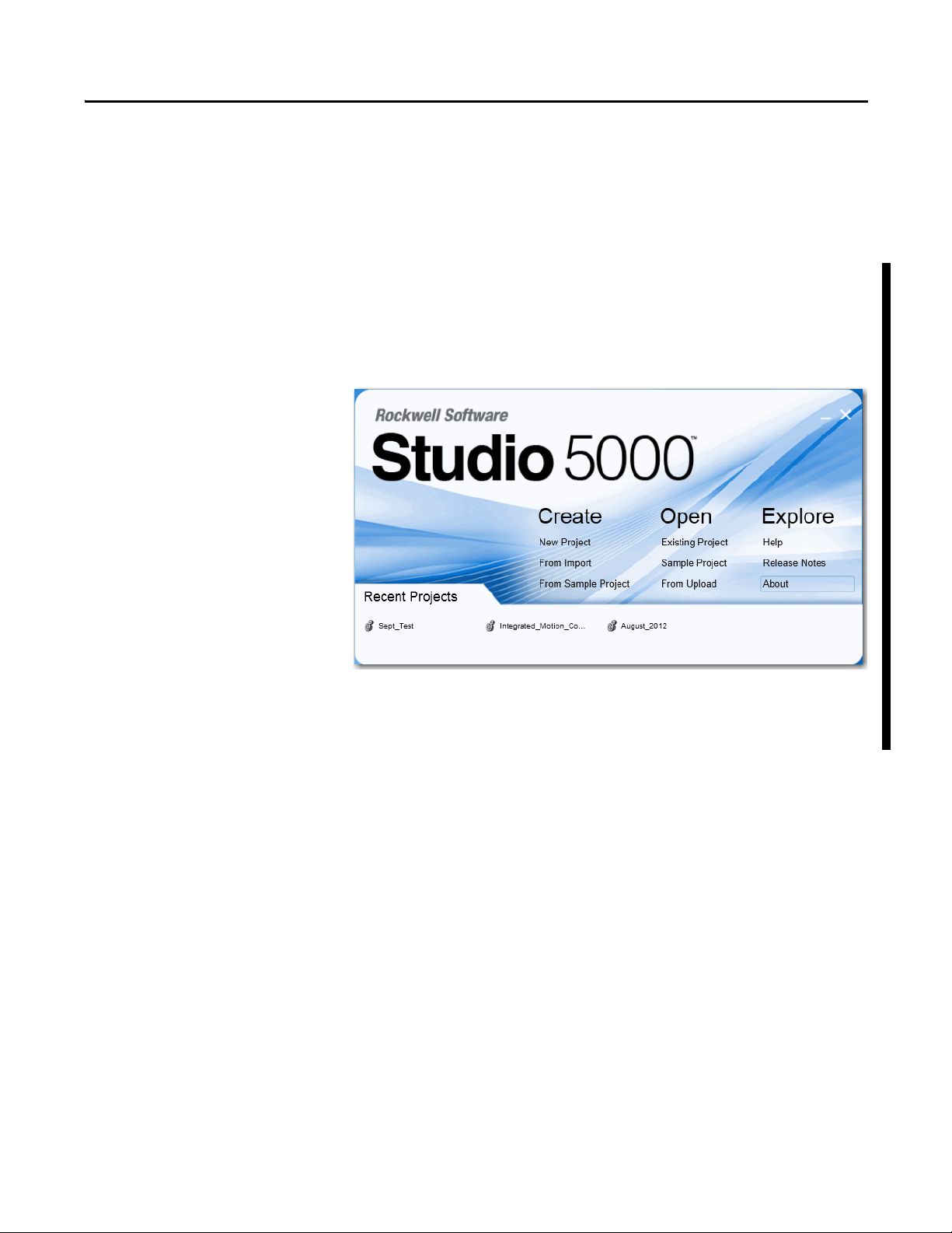
Studio 5000 Environment
The Studio 5000 Engineering and Design Environment combines engineering
and design elements into a common environment. The first element in the
Studio 5000 environment is the Logix Designer application. The Logix Designer
application is the rebranding of RSLogix 5000 software and will continue to be
the product to program Logix5000™ controllers for discrete, process, batch,
motion, safety, and drive-based solutions.
The Studio 5000 environment is the foundation for the future of Rockwell
Automation® engineering design tools and capabilities. It is the one place for
design engineers to develop all the elements of their control system.
Rockwell Automation Publication 1756-UM005B-EN-P - January 2013 9
Preface
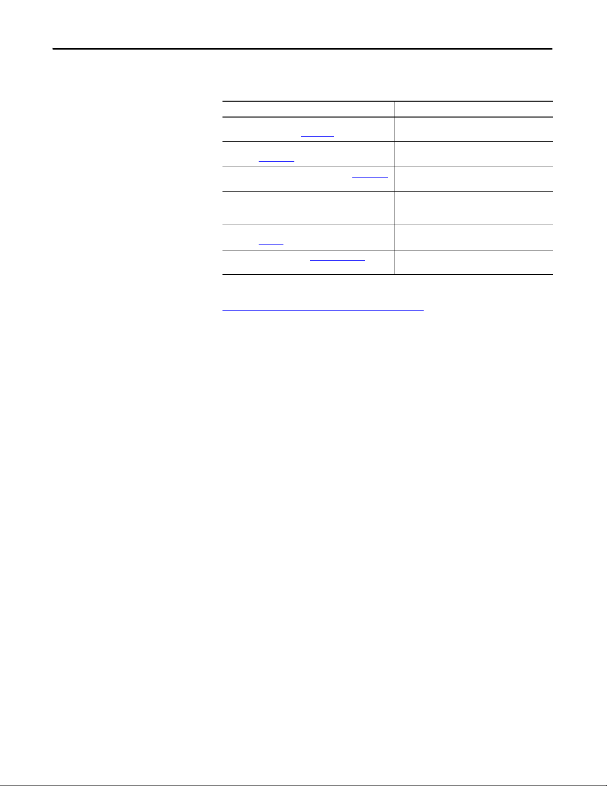
Additional Resources
These documents contain additional information concerning related products
from Rockwell Automation.
Resource Description
1756 ControlLogix I/O Modules Specifications
Technical Data, publication 1756-TD002
ControlLogix Analog I/O Modules User Manual,
publication 1756-UM009
ControlLogix System User Manual, publication 1756-UM001 Describes how to install, configure, program, and
ControlLogix Chassis and Power Supplies Installation
Instructions, publication 1756-IN005
Industrial Automation Wiring and Grounding Guidelines,
publication 1770-4.1
Product Certifications website, http://www.ab.com Provides declarations of conformity, certificates, and
Provides specifications for ControlLogix I/O modules.
Describes how to install, configure, and troubleshoot
ControlLogix analog I/O modules.
operate a ControlLogix system.
Describes how to install and troubleshoot standard and
ControlLogix-XT™ versions of the 1756 chassis and
power supplies, including redundant power supplies.
Provides general guidelines for installing a Rockwell
Automation industrial system.
other certification details.
You can view or download publications at
http://www.rockwellautomation.com/literature/
. To order paper copies of
technical documentation, contact your local Allen-Bradley distributor or
Rockwell Automation sales representative.
10 Rockwell Automation Publication 1756-UM005B-EN-P - January 2013

Chapter 1
What is the ControlLogix
High-speed Analog I/O Module?
Top ic Pag e
Available Features 11
High-speed Analog I/O Modules in the ControlLogix System 12
The ControlLogix high-speed analog I/O module is an interface module that
converts analog signals to digital values for inputs and converts digital values to
analog signals for outputs. Using the producer/consumer network model, the
module produces information when needed while providing additional system
functions.
Available Features
The following are some of the features available on the module:
• Input Synchronization—This feature lets you synchronize the sampling of
inputs across multiple fast analog modules in the same chassis, allowing
those inputs to sample at the same rate within microseconds of each other.
For more information, see Synchronize Module Inputs
• Combination module offering 4 differential inputs and 2 outputs
• Sub-millisecond input sampling
• One millisecond output updates
• On-board alarms and scaling
• Removal and insertion under power (RIUP)
• Producer/consumer communication
• Rolling timestamp of data in milliseconds
• Coordinated System Time (CST) timestamp of data in microseconds
• IEEE 32 bit floating point
• Class I/Division 2, UL, CSA, CE, and C-Tick Agency Certification
To see a complete listing, including detailed explanations of all module features,
see Chapter 3
.
on page 45.
Rockwell Automation Publication 1756-UM005B-EN-P - January 2013 11
Chapter 1 What is the ControlLogix High-speed Analog I/O Module?
IMPORTANT
Control Logix
Backplane
Connector
Removable
Ter mi nal Bl ock
Indicators
Locking Tab
Slots for
Keying the
RTB
Connector Pins
Top an d
Bottom
Guides
41623
High-speed Analog I/O Modules in the ControlLogix System
A ControlLogix high-speed analog I/O module mounts in a ControlLogix
chassis and uses a Removable Terminal Block (RTB) or Interface Module (IFM)
to connect all field-side wiring.
Before you install and use your module, do the following :
• Install and ground a 1756 chassis and power supply. Refer to the
publications listed in Additional Resources
on page 10.
• Order and receive an RTB or IFM and its components for your
application.
RTBs and IFMs are not included with your module purchase. You must order
them separately. For more information, contact your local distributor or
Rockwell Automation representative.
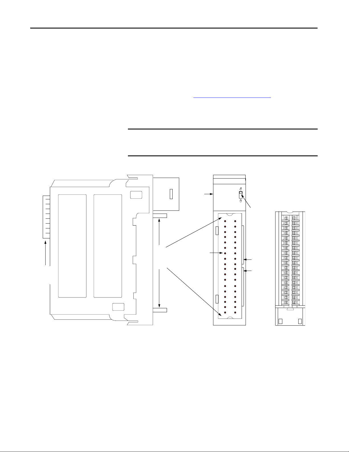
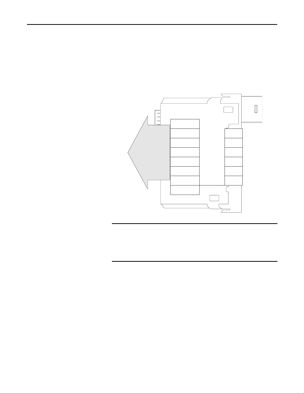
Figure 1 - Physical Features of the High-speed Analog I/O Module
12 Rockwell Automation Publication 1756-UM005B-EN-P - January 2013

What is the ControlLogix High-speed Analog I/O Module? Chapter 1
Ta b l e 1 lists the physical features on the ControlLogix high-speed analog I/O
module.
Table 1 - ControlLogix High-speed Analog I/O Module Physical Features
Feature Description
ControlLogix backplane connector Provides an interface to the ControlLogix system by connecting the module to
Connector pins Input/output, power, and grounding connections are made to the module
Locking tab Anchors the RTB on the module to maintain wiring connections.
Slots for keying Slots mechanically key the RTB to prevent you from making the wrong wire
Status indicators Display the status of communication, module health, and calibration
Top and bottom guides Provide assistance in seating the RTB onto the module.
the backplane.
through these pins with the use of an RTB.
connections to your module.
information. Use these indicators to help in troubleshooting.
Rockwell Automation Publication 1756-UM005B-EN-P - January 2013 13

Chapter 1 What is the ControlLogix High-speed Analog I/O Module?
Notes:
14 Rockwell Automation Publication 1756-UM005B-EN-P - January 2013

Chapter 2
IMPORTANT
High-speed Analog I/O Operation
in the ControlLogix System
Top ic Pag e
Ownership and Connections 16
Configure the Module 16
Direct Connections 17
Inputs and Outputs on the Same Module 18
Differences between Inputs and Outputs 20
Listen-only Mode 22
A ControlLogix high-speed analog I/O module’s performance behavior varies
depending upon whether it operates in the local chassis or in a remote chassis.
Module performance is limited in a remote chassis. The network cannot
effectively accommodate the fastest module update rates because the size of
the data broadcast requires a large portion of the network’s bandwidth. For
maximum module performance, we recommend you use it in a local chassis.
This chapter describes how the ControlLogix high-speed analog I/O module
operates in a local chassis. For more information on how the module operates
in a remote chassis, see Appendix
E.
Rockwell Automation Publication 1756-UM005B-EN-P - January 2013 15

Chapter 2 High-speed Analog I/O Operation in the ControlLogix System
Ownership and Connections
Configure the Module
Every high-speed analog I/O module in the ControlLogix system must be owned
by a ControlLogix controller. This owner-controller stores configuration data for
the module and can be local or remote in reference to the module’s position. The
owner-controller sends the high-speed analog I/O module configuration data to
define the module’s behavior and begin operation.
The ControlLogix high-speed analog I/O module is limited to a single owner
and must continuously maintain communication with the owner to operate
normally.
ControlLogix input modules allow multiple owner-controllers that each store the
module’s configuration data. The high-speed analog I/O module, however, also
has outputs and cannot support multiple owner-controllers. Other controllers
can make listen-only connections to the module, though. For more information
on listen-only connections, see page 22
The I/O configuration portion of the Studio 5000 Logix Designer application
generates the configuration data for each high-speed analog I/O module in the
control system.
With the configuration dialog boxes in the Logix Designer application, you can
configure the inputs and outputs of a high-speed analog module at the same time.
Configuration data is transferred to the owner-controller during the program
download and subsequently transferred to the appropriate modules.
.
Follow these guidelines when configuring high-speed analog I/O modules.
1. Configure all modules for the controller by using the software.
2. Download configuration information to the controller.
3. Go online with your Logix Designer project to begin operation.
For more information on how to use the software to configure the module, see
Chapter 5
.
16 Rockwell Automation Publication 1756-UM005B-EN-P - January 2013

High-speed Analog I/O Operation in the ControlLogix System Chapter 2
Direct Connections
A direct connection is a real-time data transfer link between the controller and
the module that occupies the slot that the configuration data references. When
module configuration data is downloaded to an owner-controller, the controller
attempts to establish a direct connection to each of the modules referenced by the
data.
If a controller has configuration data referencing a slot in the control system, the
controller periodically checks for the presence of a device there. When a device’s
presence is detected, the controller automatically sends the configuration data
and one of the following events occurs:
• If the data is appropriate to the module found in the slot, a connection is
made and operation begins.
• If the configuration data is not appropriate, the data is rejected, and an
error message appears in the software. In this case, the configuration data
can be inappropriate for any of a number of reasons. For example, a
module’s configuration data may be appropriate except for a mismatch in
electronic keying that prevents normal operation.
The controller continuously maintains and monitors its connection with a
module. Any break in the connection, such as removal of the module from the
chassis while under power, causes the controller to set fault status bits in the data
area associated with the module. Relay ladder logic may be used to monitor this
data area to detect the module’s failures.
Rockwell Automation Publication 1756-UM005B-EN-P - January 2013 17

Chapter 2 High-speed Analog I/O Operation in the ControlLogix System
IMPORTANT
1
2
On-Board Memory
Status Data
Channel Data
Channel Data
Channel Data
Channel Data
Input 0
Input 1
Input 2
Input 3
Timestamp
Output Data Echo
Output Data Echo
Output 0
Output 1
Inputs and Outputs on the Same Module
The ControlLogix high-speed analog I/O module has 4 inputs and 2 outputs.
The following configurable parameters affect module behavior:
• Real Time Sample (RTS)
• Requested Packet Interval (RPI)
—Defines the input update rate.
—Defines the output update rate and
additional transfers of input data.
Real Time Sample (RTS)
The RTS is a configurable parameter (0.3…25 ms) that defines the input update
rate. This parameter causes the module to do the following.
1. Scan all input channels and store the data in on-board memory.
2. Multicast the updated channel data, as well as other status data, to the
backplane of the local chassis.
18 Rockwell Automation Publication 1756-UM005B-EN-P - January 2013
The RTS value is set during the initial configuration. This value can be adjusted
anytime. To use sub-millisecond values, type values with a decimal point. For
example, to use 800 ms, type 0.8.
For more information on how to set the RTS, see Chapter 5
.
High-speed Analog I/O Operation in the ControlLogix System Chapter 2
IMPORTANT
On-Board Memory
Status Data
Channel Data
Channel Data
Channel Data
Channel Data
Timestamp
Output Data Echo
Output Data Echo
Input 0
Input 1
Input 2
Input 3
Output 0
Output 1
Requested Packet Interval (RPI)
The RPI is a configurable parameter that also instructs the module to multicast
its channel and status data to the local chassis backplane. However, the RPI
instructs the module to multicast the current contents of its on-board memory,
including input and output data echo, when the RPI expires. When the RPI
expires, the module does not update its channels prior to the multicast. The RPI
also instructs the owner-controller to update the module outputs.
The owner-controller sends output data to the high-speed analog I/O module
outputs asynchronously to when channel data and output data echo data are
returned over the ControlLogix backplane.
The RPI value is set during the initial module configuration. Adjusting the RPI
causes the connection to close and reopen.
Rockwell Automation Publication 1756-UM005B-EN-P - January 2013 19
Chapter 2 High-speed Analog I/O Operation in the ControlLogix System
IMPORTANT
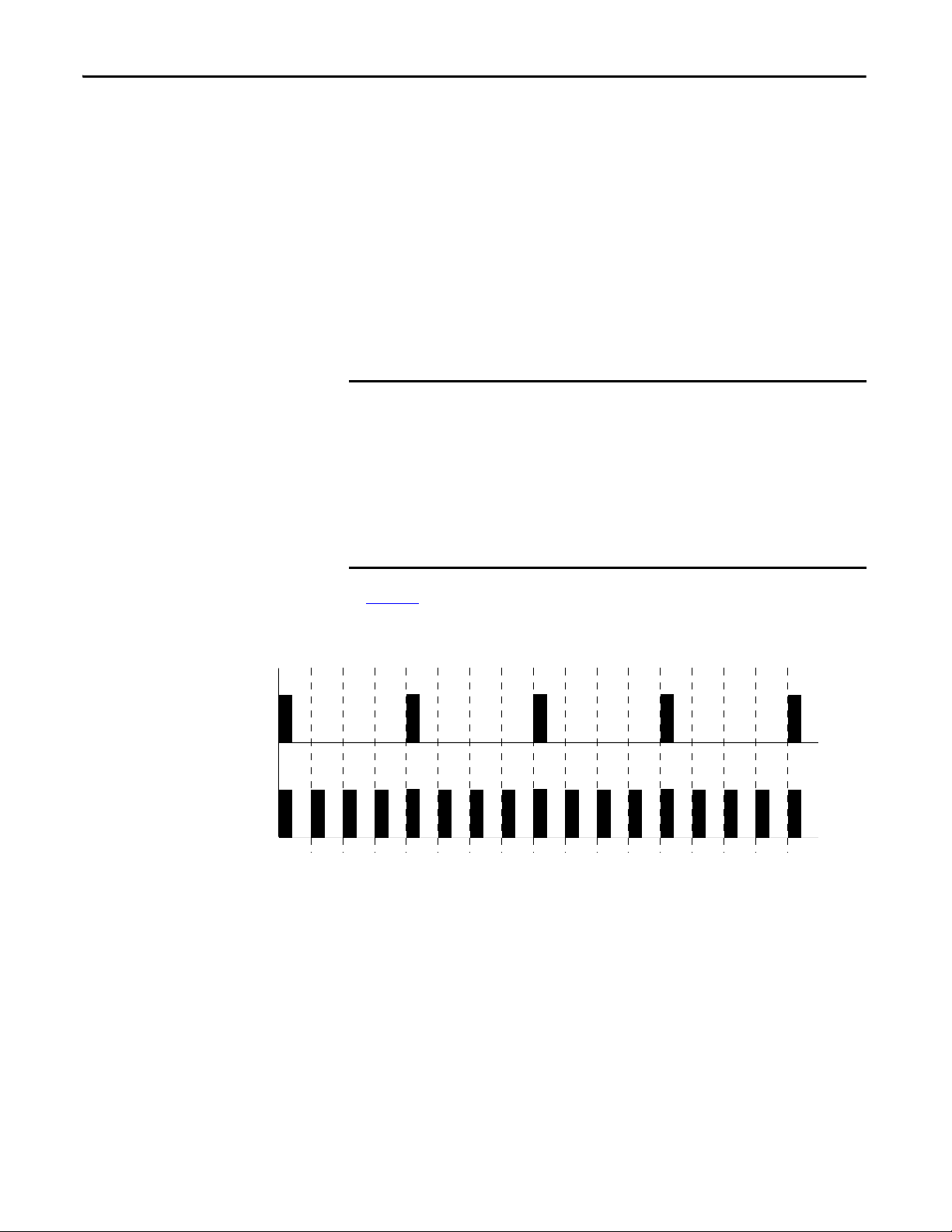
RTS
20 ms—Updated Input Data
RPI
5 ms—Updated and Old Data,
Depending on Time
5 10152025303540455055 60657075 80
Time (ms)
Updated input channel data is received at 0 ms, 20 ms, 40 ms, 60 ms, and 80 ms. The data
received at other RPI times repeats the most previous RTS. For example, data received at
30 ms repeats that received at 20 ms.
Differences between Inputs and Outputs
The ControlLogix high-speed analog I/O module uses both inputs and outputs.
However, there are significant differences between how each channel type
operates.
Module Input Operation
In traditional I/O systems, controllers poll module inputs to obtain their status.
The owner-controller does not poll the ControlLogix high-speed analog inputs
once a connection is established. Rather, the module multi-casts its input data
periodically. Multicast frequency depends on module configuration, such as RTS
and RPI rates.
The module only sends data at the RPI in these scenarios:
• RPI < RTS. In this case, the module multicasts at both the RTS rate and the
RPI rate. Their respective values dictate how often the owner-controller
receives data and how many multicasts from the module contain updated
channel data.
• If the RPI > RTS, each multicast from the module has updated channel
data. In effect, the module is only multicasting at the RTS rate.
• The module is operating in a mode where inputs are not being sampled, for
example calibration.
In Figure 2
, the RTS value is 20 ms and the RPI value is 5 ms. Only every fourth
multicast contains updated channel data.
Figure 2 - Input Data Update Rate
20 Rockwell Automation Publication 1756-UM005B-EN-P - January 2013
High-speed Analog I/O Operation in the ControlLogix System Chapter 2
Data Sent from Owner at the RPI
Owner-controller High-speed Analog I/O Module
Module Output Operation
When specifying an RPI value for the high-speed analog I/O module, you define
when the controller broadcasts output data to the module. If the module resides
in the same chassis as the owner-controller, the module receives the data almost
immediately.
High-speed analog module outputs receive data from the owner-controller and
echo output data only at the period specified in the RPI. Data is not sent to the
module at the end of the controller’s program scan.
When a high-speed analog I/O module receives new data from an
owner-controller, the module multicasts or echoes the output data value that
corresponds to the analog signal applied to the output terminals
the control system at the next RPI or RTS, whichever occurs first. This feature,
called Output Data Echo.
Depending on the value of the RPI, with respect to the length of the controller
program scan, the module can receive and echo data multiple times during one
program scan.
(1)
to the rest of
Because it is not dependent on reaching the end of the program to send data, the
controller effectively allows the module’s output channels to change values
multiple times during a single program scan when the RPI is less than the
program scan length.
(1) Although the output value at the RTB screw terminal typically matches the output data e cho value, it is not guaranteed to match.
The output data echo that is multicast to the rest of the control system represents the value the outputs were commanded to be.
Rockwell Automation Publication 1756-UM005B-EN-P - January 2013 21

Chapter 2 High-speed Analog I/O Operation in the ControlLogix System
IMPORTANT
Listen-only Mode
Any controller in the system can listen to the data from a high-speed analog I/O
module (input data or echoed output data) even if the controller does not own
the module. The module does not have to hold the module’s configuration data
to listen to the module.
During the I/O configuration process, you can specify a Listen-only mode in the
Communication Format field. For more information on Communication
Format, see page 75
Choosing a Listen-only mode option allows the controller and module to
establish communication without the controller sending any configuration data.
In this instance, another controller owns the module being listened to and stores
the module’s configuration data.
.
Controllers using the Listen-only mode continue to receive data multicast from
the I/O module as long as a connection between an owner and I/O module is
maintained.
If the connection between the owner and the module is broken, the module
stops multicasting data and connections to all listening controllers are also
broken.
22 Rockwell Automation Publication 1756-UM005B-EN-P - January 2013

Chapter 3
Module Features
Top ic Pag e
Input Compatibility 23
Output Compatibility 23
General Module Features 24
Electronic Keying 25
Understand Module Resolution, Scaling and Data Format 35
Features Specific to ModuleInputs 37
Features Specific to Module Outputs 46
Fault and Status Reporting 49
Input Compatibility
Output Compatibility
ControlLogix high-speed analog I/O module inputs convert the following
analog signals into digital values:
• Vo l t s
• Milliamps
The digital value that represents the magnitude of the analog signal is then
transmitted on the backplane to an owner-controller or other control entities.
ControlLogix high-speed analog I/O module outputs convert a digital value
delivered to the module via the backplane into an analog signal:
• -10.5…10.5V
or
• 0…21 mA
The digital value represents the magnitude of the desired analog signal. The
module converts the digital value into an analog signal and provides this signal on
the module's screw terminals.
Rockwell Automation Publication 1756-UM005B-EN-P - January 2013 23

Chapter 3 Module Features
General Module Features
This section describes features available on ControlLogix high-speed analog I/O
modules that are common with other ControlLogix I/O modules.
Removal and Insertion Under Power (RIUP)
ControlLogix high-speed analog I/O modules may be inserted and removed
from the chassis while power is applied. This feature allows greater availability of
the overall control system because, while the module is being removed or
inserted, there is no additional disruption to the rest of the controlled process.
Module Fault Reporting
ControlLogix high-speed analog I/O modules provide both hardware and
software indication when a module fault has occurred. Each module has a fault
status indicator. The Logix Designer application graphically displays the fault
and includes a fault message describing the nature of the fault. This feature lets
you to determine how your module has been affected and what action to take to
resume normal operation.
For more information about fault and status reporting, see page 49
.
Fully Software Configurable
The Logix Designer application uses an interface to configure the module. All
module features are enabled or disabled through the I/O configuration portion
of the application.
The user can also use the software to interrogate any module in the system to
retrieve the following:
• Serial number
• Revision information
• Catalog number
• Vendor identification
• Error/fault information
• Diagnostic counters
24 Rockwell Automation Publication 1756-UM005B-EN-P - January 2013
Module Features Chapter 3
IMPORTANT
Electronic Keying
The electronic keying feature automatically compares the expected module, as
shown in the Logix Designer I/O Configuration tree, to the physical module
before I/O communication begins. You can use electronic keying to help prevent
communication to a module that does not match the type and revision expected.
For each module in the I/O Configuration tree, the user-selected keying option
determines if, and how, an electronic keying check is performed. Typically, three
keying options are available:
• Exact Match
• Compatible Keying
• Disabled Keying
You must carefully consider the benefits and implications of each keying option
when selecting between them. For some specific module types, fewer options are
available.
Electronic keying is based on a set of attributes unique to each product revision.
When a Logix5000 controller begins communicating with a module, this set of
keying attributes is considered.
Table 2 - Keying Attributes
Attribute Description
Vendor The manufacturer of the module, for example, Rockwell Automation/Allen-Bradley.
Product Type The general type of the module, for example, communication adapter, AC drive, or digital
I/O.
Product Code The specific type of module, generally represented by its catalog number, for example,
1756-IB16I.
Major Revision A number that represents the functional capabilities and data exchange formats of the
module. Typically, although not always, a later, that is higher, Major Revision supports at
least all of the data formats supported by an earlier, that is lower, Major Revision of the
same catalog number and, possibly, additional ones.
Minor Revision A number that indicates the module’s specific firmware revision. Minor Revisions
typically do not impact data compatibility but may indicate performance or behavior
improvement.
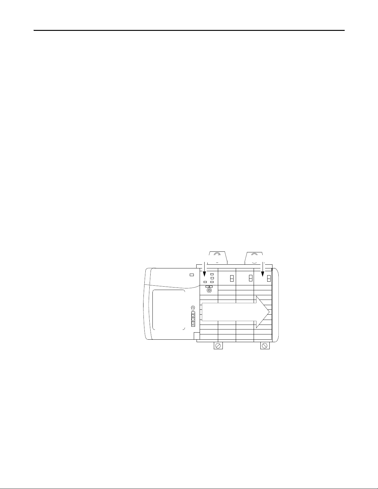
You can find revision information on the General tab of a module’s Properties
dialog box.
Figure 3 - General Tab
Changing electronic keying selections online may cause the I/O
communication connection to the module to be disrupted and may result in a
loss of data.
Rockwell Automation Publication 1756-UM005B-EN-P - January 2013 25
Chapter 3 Module Features
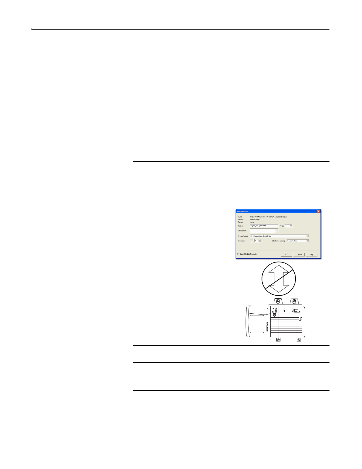
EXAMPLE
IMPORTANT
Module Configuration
Vendor = Allen-Bradley
Product Type = Digital Input Module
Catalog Number = 1756-IB16D
Major Revision = 3
Minor Revision = 1
Physical Module
Vendor = Allen-Bradley
Product Type = Digital Input Module
Catalog Number = 1756-IB16D
Major Revision = 3
Minor Revision = 2
Communication is prevented.
Exact Match
Exact Match keying requires all keying attributes, that is, Vendor, Product Type,
Product Code (catalog number), Major Revision, and Minor Revision, of the
physical module and the module created in the software to match precisely to
establish communication. If any attribute does not match precisely, I/O
communication is not permitted with the module or with modules connected
through it, as in the case of a communication module.
Use Exact Match keying when you need the system to verify that the module
revisions in use are exactly as specified in the project, such as for use in highlyregulated industries. Exact Match keying is also necessary to enable Automatic
Firmware Update for the module via the Firmware Supervisor feature from a
Logix5000 controller.
In this scenario, Exact Match keying prevents I/O communication.
The module configuration is for a 1756-IB16D module with module revision
3.1. The physical module is a 1756-IB16D module with module revision 3.2. In
this case, communication is prevented because the Minor Revision of the
module does not match precisely.
26 Rockwell Automation Publication 1756-UM005B-EN-P - January 2013
Changing electronic keying selections online may cause the I/O
Communication connection to the module to be disrupted and may result in a
loss of data.

Module Features Chapter 3
Compatible Keying
Compatible Keying indicates that the module determines whether to accept or
reject communication. Different module families, communication adapters, and
module types implement the compatibility check differently based on the family
capabilities and on prior knowledge of compatible products. Release notes for
individual modules indicate the specific compatibility details.
Compatible Keying is the default setting. Compatible Keying allows the physical
module to accept the key of the module configured in the software, provided that
the configured module is one the physical module is capable of emulating. The
exact level of emulation required is product and revision specific.
With Compatible Keying, you can replace a module of a certain Major Revision
with one of the same catalog number and the same or later, that is higher, Major
Revision. If a Major Revision is the same, then make sure that the Minor Revision
is the same or higher than it is configured in the project. In some cases, the
selection makes it possible to use a replacement that is a different catalog number
than the original. For example, you can replace a 1756-CNBR module with a
1756-CN2R module.
When a module is created, the module developers consider the module’s
development history to implement capabilities that emulate those of the previous
module. However, the developers cannot know future developments. Because of
this, when a system is config ured, we recommend that you configure your module
using the earliest, that is, lowest, revision of the physical module that you believe
will be used in the system. By doing this, you can avoid the case of a physical
Rockwell Automation Publication 1756-UM005B-EN-P - January 2013 27
Chapter 3 Module Features
EXAMPLE
Module Configuration
Vendor = Allen-Bradley
Product Type = Digital Input Module
Catalog Number = 1756-IB16D
Major Revision = 3
Minor Revision = 3
Physical Module
Vendor = Allen-Bradley
Product Type = Digital Input Module
Catalog Number = 1756-IB16D
Major Revision = 3
Minor Revision = 2
Communication is prevented.
module rejecting the keying request because it is an earlier revision than the one
configured in the software.
In this scenario, Compatible Keying prevents I/O communication.
The module configuration is for a 1756-IB16D module with module revision
3.3. The physical module is a 1756-IB16D module with module revision 3.2.
In this case, communication is prevented because the minor revision of the
module is lower than expected and may not be compatible with 3.3.
28 Rockwell Automation Publication 1756-UM005B-EN-P - January 2013

Module Features Chapter 3
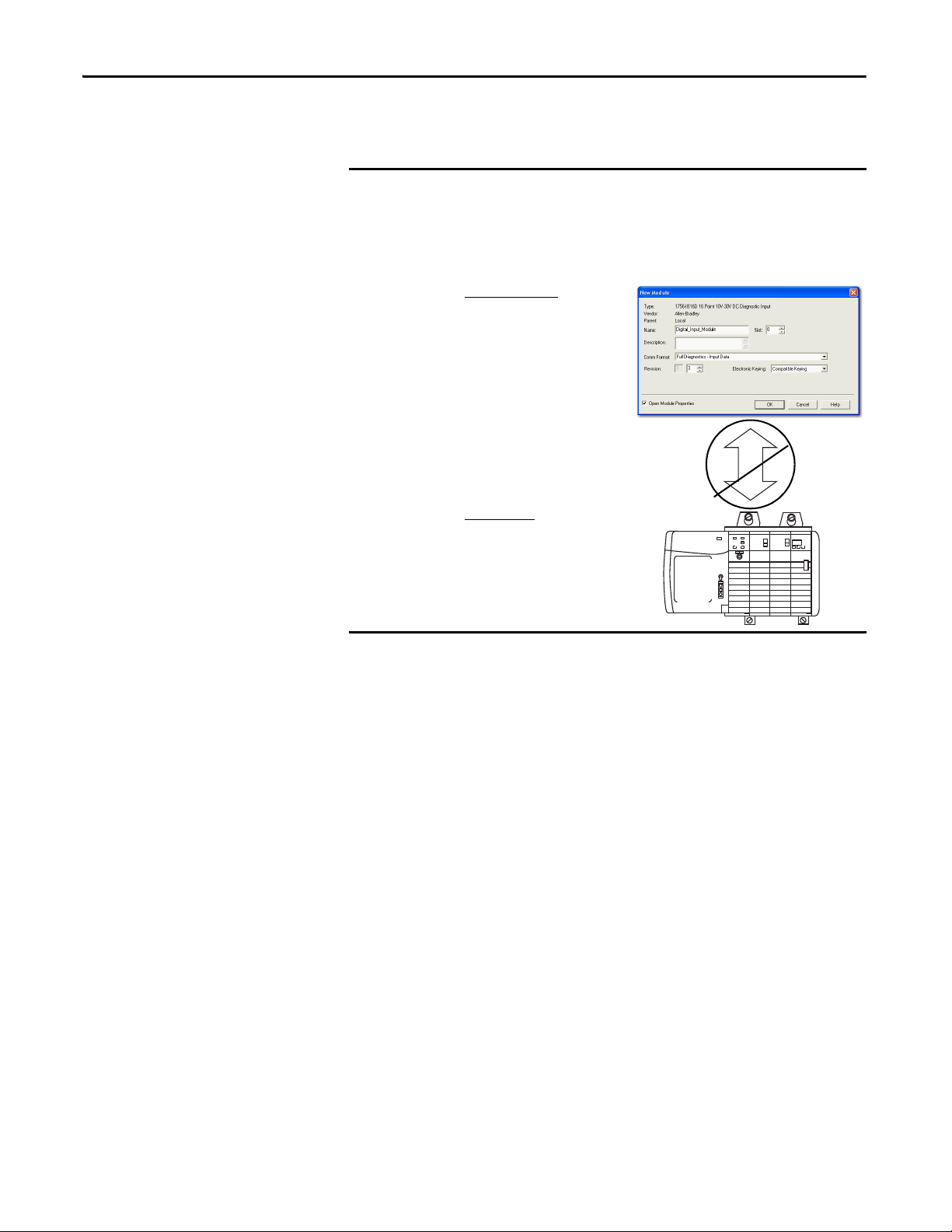
EXAMPLE
IMPORTANT
Module Configuration
Vendor = Allen-Bradley
Product Type = Digital Input Module
Catalog Number = 1756-IB16D
Major Revision = 2
Minor Revision = 1
Physical Module
Vendor = Allen-Bradley
Product Type = Digital Input Module
Catalog Number = 1756-IB16D
Major Revision = 3
Minor Revision = 2
Communication is allowed.
In this scenario, Compatible Keying allows I/O communication.
The module configuration is for a 1756-IB16D module with module revision
2.1. The physical module is a 1756-IB16D module with module revision 3.2. In
this case, communication is allowed because the major revision of the physical
module is higher than expected and the module determines that it is
compatible with the prior major revision.
Changing electronic keying selections online may cause the I/O
communication connection to the module to be disrupted and may result in a
loss of data.
Rockwell Automation Publication 1756-UM005B-EN-P - January 2013 29
Chapter 3 Module Features
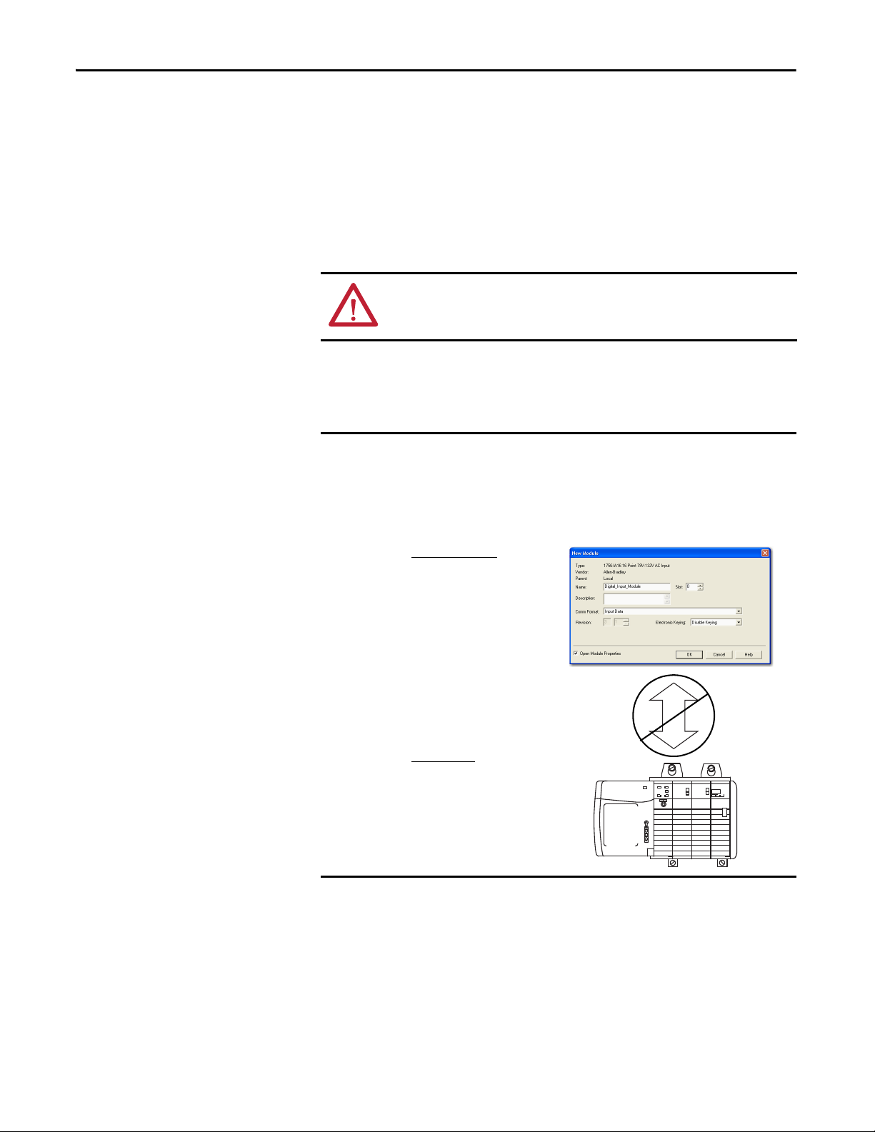
EXAMPLE
Module Configuration
Vendor = Allen-Bradley
Product Type = Digital Input Module
Catalog Number = 1756-IA16
Major Revision = 3
Minor Revision = 1
Physical Module
Vendor = Allen-Bradley
Product Type = Analog Input Module
Catalog Number = 1756-IF16
Major Revision = 3
Minor Revision = 2
Communication is prevented.
Disabled Keying
Disabled Keying indicates the keying attributes are not considered when
attempting to communicate with a module. Other attributes, such as data size
and format, are considered and must be acceptable before I/O communication is
established. With Disabled Keying, I/O communication may occur with a
module other than the type specified in the I/O Configuration tree with
unpredictable results. We generally do not recommend using Disabled Keying.
ATT EN TI ON : Be extremely cautious when using Disabled Keying; if used
incorrectly, this option can lead to personal injury or death, property damage,
or economic loss.
If you use Disabled Keying, you must take full responsibility for understanding
whether the module being used can fulfill the functional requirements of the
application.
In this scenario, Disable Keying prevents I/O communication.
The module configuration is for a 1756-IA16 digital input module. The physical
module is a 1756-IF16 analog input module. In this case, communication is
prevented because the analog module rejects the data formats that the digital
module configuration requests.
30 Rockwell Automation Publication 1756-UM005B-EN-P - January 2013
Loading...