


 Loading...
Allen-Bradley
MicroLogixt 1000 with Hand-Held Programmer (HHP)
(Cat. No. 1761-HHP-B30)
User
Manual

Important User
Information
Because of the variety of uses for the products described in this publication, those responsible for the application and use of this control equipment must satisfy themselves that all necessary steps have been taken to assure that each application and use meets all performance and safety requirements, including any applicable laws, regulations, codes and standards.
The illustrations, charts, sample programs and layout examples shown in this guide are intended solely for purposes of example. Since there are many variables and requirements associated with any particular installation, Allen-Bradley does not assume responsibility or liability (to include intellectual property liability) for actual use based upon the examples shown in this publication.
Allen-Bradley publication SGI-1.1, Safety Guidelines for the Application, Installation, and Maintenance of Solid-State Control
(available from your local Allen-Bradley office), describes some important differences between solid-state equipment and electromechanical devices that should be taken into consideration when applying products such as those described in this publication.
Reproduction of the contents of this copyrighted publication, in whole or in part, without written permission of Allen-Bradley Company, Inc., is prohibited.
Throughout this manual we use notes to make you aware of safety considerations:
|
ATTENTION: Identifies information about practices |
|
! |
or circumstances that can lead to personal injury or |
|
death, property damage or economic loss. |
||
|
||
|
|
Attention statements help you to:
•identify a hazard
•avoid the hazard
•recognize the consequences
Important: Identifies information that is critical for successful application and understanding of the product.
SLC 500 and MicroLogix are trademarks of Rockwell Automation.

Preface
Preface
Who Should Use this Manual
Purpose of this Manual
Read this preface to familiarize yourself with the rest of the manual. This preface covers the following topics:
•who should use this manual
•the purpose of this manual
•how to use this manual
•conventions used in this manual
•Allen-Bradley support
Use this manual if you are responsible for designing, installing, programming, or troubleshooting control systems that use Allen-Bradley micro controllers.
You should have a basic understanding of electrical circuitry and familiarity with relay logic. If you do not, obtain the proper training before using this product.
This manual is a reference guide for the MicroLogixt 1000 Programmable Controller with a MicroLogix 1000 Hand-Held Programmer (HHP). It describes the procedures you use to install, wire, and program your micro controller. This manual:
•gives you an overview of the micro controller system
•provides a quick start chapter for beginners
•describes how to use the Hand-Held Programmer
•guides you through how to interpret the instruction set
•contains application examples to show the instruction set in use
If you are using programming software with your MicroLogix 1000 Programmable Controller, see page P±4 for related publications.
P±1

Preface
Contents of this Manual
Tab |
Chapter |
Title |
Contents |
|
|
|
|
|
|
|
|
|
Describes the purpose, background, and scope of this |
|
|
|
Preface |
manual. Also specifies the audience for whom this |
|
|
|
|
manual is intended. |
|
|
|
|
|
|
|
1 |
Installing Your Controller |
Provides controller installation procedures and system |
|
|
safety considerations. |
|||
|
|
|
||
|
|
|
|
|
Installing |
2 |
Wiring Your Controller |
Provides wiring guidelines and diagrams. |
|
|
|
|
|
|
|
3 |
Connecting the System |
Gives information on wiring your controller system for the |
|
|
DF1 protocol or DH-485 network. |
|||
|
|
|
||
|
|
|
|
|
|
|
Using Your Hand-Held |
Describes how to power-up and use your MicroLogix 1000 |
|
|
4 |
Hand-Held Programmer (HHP). Also explains how to |
||
|
Programmer |
|||
|
|
install the HHPs memory module. |
||
|
|
|
||
|
|
|
|
|
|
5 |
Quick Start for New Users |
Provides step-by-step instructions on how to enter a |
|
|
program, edit it, and then monitor it. |
|||
|
|
|
||
|
|
|
|
|
|
|
|
Provides an overview of principles of machine control, a |
|
|
6 |
Programming Overview |
section on file organization and addressing, and a |
|
|
|
|
program development model. |
|
|
|
|
|
|
|
|
|
Provides information on I/O image file format, I/O |
|
|
7 |
Using Analog |
configuration, input filter and update times and conversion |
|
|
|
|
of analog data. |
|
|
|
|
|
|
|
8 |
Using Basic Instructions |
Describes how to use the instructions for relay |
|
|
replacement functions, counting, and timing. |
|||
|
|
|
||
|
|
|
|
|
|
9 |
Using Comparison |
Describes how to use the instructions to compare values |
|
Programming |
Instructions |
of data in your logic program. |
||
|
||||
|
|
|
||
|
10 |
Using Math Instructions |
Describes how to use the instructions that perform basic |
|
|
math functions. |
|||
|
|
|
||
|
|
|
|
|
|
|
Using Data Handling |
Describes how to perform data handling instructions, |
|
|
11 |
including move and logical instructions and FIFO and |
||
|
Instructions |
|||
|
|
LIFO instructions. |
||
|
|
|
||
|
|
|
|
|
|
12 |
Using Program Flow |
Describes the instructions that affect program flow and |
|
|
Control Instructions |
execution. |
||
|
|
|||
|
|
|
|
|
|
13 |
Using Application Specific |
Describes the bit shift, sequencer and STI related |
|
|
Instructions |
instructions. |
||
|
|
|||
|
|
|
|
|
|
14 |
Using High-Speed |
Describes the four modes of the high-speed counter |
|
|
Counter Instructions |
instruction and its related instructions. |
||
|
|
|||
|
|
|
|
|
|
|
Using Communication |
Provides a general overview of the types of |
|
|
15 |
communication, and explains how to establish network |
||
|
Protocols |
|||
|
|
communication using the message instruction. |
||
|
|
|
||
|
|
|
|
P±2

Preface
Tab |
Chapter |
|
|
|
|
|
16 |
|
|
|
|
|
17 |
|
Programming |
|
|
18 |
||
|
||
|
|
|
|
19 |
|
|
|
|
Troubleshooting |
20 |
|
|
|
|
|
Appendix A |
|
|
|
|
|
Appendix B |
|
Reference |
|
|
Appendix C |
||
|
||
|
|
|
|
Appendix D |
|
|
|
|
Reference |
Appendix E |
|
|
|
|
Reference |
Appendix F |
|
|
|
|
|
|
Title |
Contents |
|
|
|
|
Instruction List |
Provides examples to teach you Instruction List |
|
Programming |
programming and describes programming considerations. |
|
|
|
|
Entering and Editing Your |
Describes the various editing functions you can use with |
|
Program |
your program, including search, overwrite, and delete. |
|
|
|
|
After You've Entered Your |
Describes how to configure, run, and monitor your |
|
Program |
program. |
|
|
|
|
Common Procedures |
Describes how to perform additional procedures using the |
|
HHP menu. |
||
|
||
|
|
|
Troubleshooting Your |
Explains how to interpret and correct problems with your |
|
System |
micro controller system. |
|
|
|
|
Hardware Reference |
Provides physical, electrical, environmental, and |
|
functional specifications. |
||
|
||
|
|
|
Programming Reference |
Explains the system status file, lists the HHP function |
|
codes, and provides instruction execution times. |
||
|
||
|
|
|
Valid Addressing Modes |
Provides a listing of the instructions along with their |
|
and File Types for |
||
parameters and valid file types. |
||
Instruction Parameters |
||
|
||
|
|
|
Understanding the |
Contains descriptions of the DF1 protocol and DH-485 |
|
Communication Protocols |
network. |
|
|
|
|
Application Programs |
Provides advanced application examples for the |
|
high-speed counter, sequencer, and bit shift instructions. |
||
|
||
|
|
|
Optional Analog Input |
Explains how to calibrate your controller using software |
|
Software Calibration |
offsets. |
|
|
|
|
Glossary |
Contains definitions for terms and abbreviations that are |
|
specific to this product. |
||
|
||
|
|
 For More Information
As part of our effort to preserve, protect, and improve our environment, Allen-Bradley is reducing the amount of paper we use. Less paper means more options for you. In addition to traditional printed publications and CD-ROM versions, we now offer on-line manuals with the most up-to-date information you can get. We recommend that you read the related publications listed on the next page before starting up your control system.
P±3

Preface
Related Publications
|
|
For |
Read this Document |
Document Number |
|||
|
|
|
|
|
|
|
|
|
|
A description on how to install and use your MicroLogixt 1000 |
|
t |
1000 Programmable |
|
|
|
|
Programmable Controllers. This manual also contains status file |
MicroLogix |
|
1761-6.3 |
||
|
|
Controllers User Manual |
|||||
|
|
data and instruction set information |
|
||||
|
|
|
|
|
|
|
|
|
|
|
|
|
|
|
|
|
|
A reference manual that contains the status file data and the |
SLC 500 |
t |
|
t |
|
|
|
instruction set information for the SLC 500 processors and |
|
and MicroLogix 1000 |
1747-6.15 |
||
|
|
Instruction Set Reference Manual |
|||||
|
|
MicroLogix 1000 controllers |
|
||||
|
|
|
|
|
|
|
|
|
|
|
|
|
|||
|
|
|
MicroLogixt 1000 Programmable |
1761-5.1.2 |
|||
|
|
Information on mounting and wiring the MicroLogix 1000 |
Controllers Installation Instructions |
||||
|
|
|
|||||
|
|
|
|
|
|
|
|
|
|
controllers, including a mounting template for easy installation |
|
t |
1000 (Analog) Programmable |
|
|
|
|
|
MicroLogix |
|
1761-5.1.3 |
||
|
|
|
Controllers Installation Instructions |
||||
|
|
|
|
||||
|
|
|
|
|
|||
|
|
The procedures necessary to install and connect the AIC+ and |
Advanced Interface Converter (AIC+) and |
|
|||
|
|
DeviceNet Interface (DNI) Installation |
1761-5.11 |
||||
|
|
DNI |
|||||
|
|
Instructions |
|
|
|
||
|
|
|
|
|
|
||
|
|
|
|
|
|||
|
|
A description on how to install and connect an AIC+. This |
Advanced Interface Converter (AIC+) User |
1761-6.4 |
|||
|
|
manual also contains information on network wiring. |
Manual |
|
|
|
|
|
|
|
|
|
|
||
|
|
|
|
|
|||
|
|
Information on how to install, configure, and commission a DNI |
DeviceNet Interfacet User Manual |
1761-6.5 |
|||
|
|
In-depth information on grounding and wiring Allen-Bradley |
Allen-Bradley Programmable Controller |
1770-4.1 |
|||
|
|
programmable controllers |
Grounding and Wiring Guidelines |
||||
|
|
|
|||||
|
|
|
|
|
|
|
|
|
How to Get More Information |
|
|
|||
|
|
|
|
|
||
For |
|
|
Obtain Information By |
|
||
|
|
|||||
Fast access to |
•Visiting the MicroLogix internet site http://www.abmicrologix.com Ð Electronic versions of our |
|||||
related |
manuals are available for you to search and down load. |
|
||||
publications |
•Calling local Allen-Bradley distributor. |
|
|
|||
|
|
|
||||
Publications in |
Ordering a manual or CD-ROM using one of the following methods: |
|
||||
printed or |
•Fill out and return the User Manual Request Card that was shipped with the unit. |
|||||
CD-ROM format |
•Visiting the Automation Bookstore at http://www.theautomationbookstore.com |
|||||
|
|
|
|
|
|
|
Multiple copies of |
•Visiting the Automation Bookstore at http://www.theautomationbookstore.com |
|||||
a manual |
||||||
|
|
|
|
|
||
|
|
|||||
Manuals in other |
Adding a 2-letter suffix to the end of the publication number when ordering. |
|||||
languages |
•French ± FR |
•German ± DE |
•Italian ± IT |
•Spanish ± ES |
•Portuguese ± PT (DNI only) |
|
|
|
|
|
|
|
|
P±4
Preface
Related Documentation
The following documents contain additional information concerning Allen-Bradley products. To obtain a copy, contact your local Allen-Bradley office or distributor.
For
A description of important differences between solid-state programmable controller products and hard-wired electromechanical devices
An article on wire sizes and types for grounding electrical equipment
A complete listing of current documentation, including ordering instructions. Also indicates whether the documents are available on CD-ROM or in multi-languages.
A glossary of industrial automation terms and abbreviations
Read This Document |
Document Number |
|
|
|
|
Application Considerations for |
SGI-1.1 |
|
Solid-State Controls |
||
|
||
|
|
|
National Electrical Code |
Published by the National Fire Protection |
|
Association of Boston, MA. |
||
|
||
|
|
|
Allen-Bradley Publication Index |
SD499 |
|
|
|
|
Allen-Bradley Industrial Automation |
AG-7.1 |
|
Glossary |
||
|
||
|
|
Common Techniques Used in The following conventions are used throughout this manual:
this Manual |
• Bulleted lists such as this one provide information, not procedural steps. |
||
|
• Numbered lists provide sequential steps or hierarchical information. |
||
|
• Italic type is used for emphasis. |
||
|
• Text in this font indicates words that appear on the HHP display. |
||
|
• |
NEW |
Keypad icons, like the one at the left, match the key you |
|
RUNG |
||
T |
should press. |
|
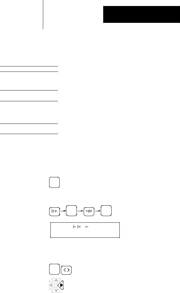
• For operations that require you to press a sequence of keys, the keypad icons are displayed horizontally on the page, with the resulting screen shown beneath. For example:
|
|
|
MENU |
ENT |
|
|
|
I |
|
|
7 |
|
6 |
|
|
|
|
||
P |
0 |
0 |
0 |
|
I |
/ |
6 |
|
0 |
•If a character is flashing on the HHP display, it is shown unbolded (such as the P in the screen above).
•For operations that require you to press two keys simultaneously, the keypad icons are displayed side-by-side as shown here:
ESC
•
1
For operations that require you to press an arrow key, the key you should press is shown bolded, such as the right arrow key shown here.
P±5

Preface
Allen-Bradley Support |
Allen-Bradley offers support services worldwide, with over 75 Sales/Support |
|
Offices, 512 authorized Distributors and 260 authorized Systems Integrators |
|
located throughout the United States alone, plus Allen-Bradley |
|
representatives in every major country in the world. |
|
Local Product Support |
|
Contact your local Allen-Bradley representative for: |
|
• sales and order support |
|
• product technical training |
|
• warranty support |
|
• support service agreements |
|
Technical Product Assistance |
|
If you need to contact Allen-Bradley for technical assistance, please review |
|
the information in the Troubleshooting chapter first. Then call your local |
|
Allen-Bradley representative. |
|
Your Questions or Comments on this Manual |
|
If you find a problem with this manual, please notify us of it on the enclosed |
|
Publication Problem Report. |
|
If you have any suggestions for how this manual could be made more useful |
|
to you, please contact us at the address below: |
|
Allen-Bradley Company, Inc. |
|
Control and Information Group |
|
Technical Communication, Dept. 602V, T122 |
|
P.O. Box 2086 |
|
Milwaukee, WI 53201-2086 |
|
or visit our internet page at: |
|
http://www.abmicrologix.com |
P±6

Table of Contents
MicroLogixt 1000 with Hand±Held Programmer (HHP) User Manual
Preface
Who Should Use this Manual . . . . . . . . . . . . . . . . . . . . . . . . . . . . . . . . . . . P±1 Purpose of this Manual . . . . . . . . . . . . . . . . . . . . . . . . . . . . . . . . . . . . . . . . P±1 Common Techniques Used in this Manual . . . . . . . . . . . . . . . . . . . . . . . . . . P±5 Allen-Bradley Support . . . . . . . . . . . . . . . . . . . . . . . . . . . . . . . . . . . . . . . . P±6
Hardware
Installing Your Controller
Wiring Your Controller
Connecting the System
Chapter 1
Compliance to European Union Directives . . . . . . . . . . . . . . . . . . . . . . . . . . |
1±1 |
Hardware Overview . . . . . . . . . . . . . . . . . . . . . . . . . . . . . . . . . . . . . . . . . . |
1±2 |
Master Control Relay . . . . . . . . . . . . . . . . . . . . . . . . . . . . . . . . . . . . . . . . . |
1±3 |
Using Surge Suppressors . . . . . . . . . . . . . . . . . . . . . . . . . . . . . . . . . . . . . . |
1±7 |
Safety Considerations . . . . . . . . . . . . . . . . . . . . . . . . . . . . . . . . . . . . . . . . |
1±9 |
Power Considerations . . . . . . . . . . . . . . . . . . . . . . . . . . . . . . . . . . . . . . . . |
1±10 |
Preventing Excessive Heat . . . . . . . . . . . . . . . . . . . . . . . . . . . . . . . . . . . . . |
1±11 |
Controller Spacing . . . . . . . . . . . . . . . . . . . . . . . . . . . . . . . . . . . . . . . . . . . |
1±12 |
Mounting the Controller . . . . . . . . . . . . . . . . . . . . . . . . . . . . . . . . . . . . . . . |
1±12 |
Chapter 2
Grounding Guidelines . . . . . . . . . . . . . . . . . . . . . . . . . . . . . . . . . . . . . . . . |
2±1 |
Sinking and Sourcing Circuits . . . . . . . . . . . . . . . . . . . . . . . . . . . . . . . . . . . |
2±2 |
Wiring Recommendations . . . . . . . . . . . . . . . . . . . . . . . . . . . . . . . . . . . . . . |
2±3 |
Wiring Diagrams, Discrete Input and Output Voltage Ranges . . . . . . . . . . . . . |
2±6 |
Minimizing Electrical Noise on Analog Controllers . . . . . . . . . . . . . . . . . . . . . |
2±20 |
Grounding Your Analog Cable . . . . . . . . . . . . . . . . . . . . . . . . . . . . . . . . . . . |
2±20 |
Wiring Your Analog Channels . . . . . . . . . . . . . . . . . . . . . . . . . . . . . . . . . . . |
2±21 |
Analog Voltage and Current Input and Output Ranges . . . . . . . . . . . . . . . . . |
2±22 |
Wiring Your Controller for High-Speed Counter Applications . . . . . . . . . . . . . |
2±23 |
Chapter 3
Connecting the HHP . . . . . . . . . . . . . . . . . . . . . . . . . . . . . . . . . . . . . . . . . |
3±1 |
Connecting to a DH-485 Network . . . . . . . . . . . . . . . . . . . . . . . . . . . . . . . . |
3±3 |
Connecting the AIC+ . . . . . . . . . . . . . . . . . . . . . . . . . . . . . . . . . . . . . . . . . |
3±6 |
Establishing Communication . . . . . . . . . . . . . . . . . . . . . . . . . . . . . . . . . . . . |
3±12 |
DeviceNet Communications . . . . . . . . . . . . . . . . . . . . . . . . . . . . . . . . . . . . |
3±13 |
toc±i

Table of Contents
MicroLogixt 1000 with Hand±Held Programmer (HHP) User Manual
Programming
Using Your Hand-Held
Programmer
Quick Start for New Users
Programming Overview
Using Analog
Using Basic Instructions
Chapter 4
About Your HHP . . . . . . . . . . . . . . . . . . . . . . . . . . . . . . . . . . . . . . . . . . . . |
4±1 |
Installing the Optional Memory Module . . . . . . . . . . . . . . . . . . . . . . . . . . . . |
4±3 |
The Keys You Use . . . . . . . . . . . . . . . . . . . . . . . . . . . . . . . . . . . . . . . . . . . |
4±4 |
Identifying the Power-Up Sequence . . . . . . . . . . . . . . . . . . . . . . . . . . . . . . . |
4±6 |
Understanding the HHPs Functional Areas . . . . . . . . . . . . . . . . . . . . . . . . . |
4±7 |
Changing the HHPs Defaults . . . . . . . . . . . . . . . . . . . . . . . . . . . . . . . . . . . |
4±17 |
Chapter 5
What to Do First . . . . . . . . . . . . . . . . . . . . . . . . . . . . . . . . . . . . . . . . . . . . |
5±1 |
Preparing to Enter a New Program . . . . . . . . . . . . . . . . . . . . . . . . . . . . . . . |
5±2 |
Entering and Running the Program . . . . . . . . . . . . . . . . . . . . . . . . . . . . . . . |
5±4 |
Monitoring Operation . . . . . . . . . . . . . . . . . . . . . . . . . . . . . . . . . . . . . . . . . |
5±9 |
What to Do Next . . . . . . . . . . . . . . . . . . . . . . . . . . . . . . . . . . . . . . . . . . . . |
5±12 |
Chapter 6
Principles of Machine Control . . . . . . . . . . . . . . . . . . . . . . . . . . . . . . . . . . . |
6±1 |
Understanding File Organization . . . . . . . . . . . . . . . . . . . . . . . . . . . . . . . . . |
6±3 |
Understanding How Programs are Stored and Accessed . . . . . . . . . . . . . . . |
6±5 |
Addressing Data Files . . . . . . . . . . . . . . . . . . . . . . . . . . . . . . . . . . . . . . . . |
6±7 |
Applying Logic to Your Schematics . . . . . . . . . . . . . . . . . . . . . . . . . . . . . . . |
6±11 |
Developing Your Logic Program ± A Model . . . . . . . . . . . . . . . . . . . . . . . . . |
6±17 |
Chapter 7
I/O Image . . . . . . . . . . . . . . . . . . . . . . . . . . . . . . . . . . . . . . . . . . . . . . . . . |
7±1 |
I/O Configuration . . . . . . . . . . . . . . . . . . . . . . . . . . . . . . . . . . . . . . . . . . . . |
7±2 |
Input Filter and Update Times . . . . . . . . . . . . . . . . . . . . . . . . . . . . . . . . . . . |
7±2 |
Converting Analog Data . . . . . . . . . . . . . . . . . . . . . . . . . . . . . . . . . . . . . . . |
7±4 |
Chapter 8
About Basic Instructions . . . . . . . . . . . . . . . . . . . . . . . . . . . . . . . . . . . . . . . |
8±2 |
Bit Instructions Overview . . . . . . . . . . . . . . . . . . . . . . . . . . . . . . . . . . . . . . |
8±3 |
Load (LD), And (AND), and Or (OR) . . . . . . . . . . . . . . . . . . . . . . . . . . . . . . |
8±3 |
Load Inverted (LDI), And Inverted (ANI), and Or Inverted (ORI) . . . . . . . . . . . |
8±4 |
Load True (LDT) and Or True (ORT) . . . . . . . . . . . . . . . . . . . . . . . . . . . . . . |
8±6 |
One-Shot Rising (OSR) . . . . . . . . . . . . . . . . . . . . . . . . . . . . . . . . . . . . . . . |
8±7 |
toc±ii
Using Comparison
Instructions
Using Math Instructions
Table of Contents
MicroLogixt 1000 with Hand±Held Programmer (HHP) User Manual
Output (OUT) . . . . . . . . . . . . . . . . . . . . . . . . . . . . . . . . . . . . . . . . . . . . . . |
8±8 |
Set (SET) and Reset (RST) . . . . . . . . . . . . . . . . . . . . . . . . . . . . . . . . . . . . |
8±8 |
Branch Instructions Overview . . . . . . . . . . . . . . . . . . . . . . . . . . . . . . . . . . . |
8±9 |
Memory Push (MPS), Memory Read (MRD), and Memory Pop (MPP) . . . . . . |
8±10 |
And Block (ANB) and Or Block (ORB) . . . . . . . . . . . . . . . . . . . . . . . . . . . . . |
8±12 |
Timer Instructions Overview . . . . . . . . . . . . . . . . . . . . . . . . . . . . . . . . . . . . |
8±14 |
Timer On-Delay (TON) . . . . . . . . . . . . . . . . . . . . . . . . . . . . . . . . . . . . . . . . |
8±16 |
Timer Off-Delay (TOF) . . . . . . . . . . . . . . . . . . . . . . . . . . . . . . . . . . . . . . . . |
8±18 |
Retentive Timer (RTO) . . . . . . . . . . . . . . . . . . . . . . . . . . . . . . . . . . . . . . . . |
8±20 |
Counter Instructions Overview . . . . . . . . . . . . . . . . . . . . . . . . . . . . . . . . . . |
8±21 |
Count Up (CTU) . . . . . . . . . . . . . . . . . . . . . . . . . . . . . . . . . . . . . . . . . . . . |
8±24 |
Count Down (CTD) . . . . . . . . . . . . . . . . . . . . . . . . . . . . . . . . . . . . . . . . . . |
8±25 |
Reset (RES) . . . . . . . . . . . . . . . . . . . . . . . . . . . . . . . . . . . . . . . . . . . . . . . |
8±27 |
Basic Instructions in the Paper Drilling Machine Application Example . . . . . . . |
8±28 |
Chapter 9
About the Comparison Instructions . . . . . . . . . . . . . . . . . . . . . . . . . . . . . . . |
9±2 |
Comparison Instructions Overview . . . . . . . . . . . . . . . . . . . . . . . . . . . . . . . |
9±2 |
Equal (EQU) . . . . . . . . . . . . . . . . . . . . . . . . . . . . . . . . . . . . . . . . . . . . . . . |
9±3 |
Not Equal (NEQ) . . . . . . . . . . . . . . . . . . . . . . . . . . . . . . . . . . . . . . . . . . . . |
9±4 |
Less Than (LES) . . . . . . . . . . . . . . . . . . . . . . . . . . . . . . . . . . . . . . . . . . . . |
9±5 |
Less Than or Equal (LEQ) . . . . . . . . . . . . . . . . . . . . . . . . . . . . . . . . . . . . . |
9±6 |
Greater Than (GRT) . . . . . . . . . . . . . . . . . . . . . . . . . . . . . . . . . . . . . . . . . . |
9±7 |
Greater Than or Equal (GEQ) . . . . . . . . . . . . . . . . . . . . . . . . . . . . . . . . . . . |
9±8 |
Masked Comparison for Equal (MEQ) . . . . . . . . . . . . . . . . . . . . . . . . . . . . . |
9±9 |
Limit Test (LIM) . . . . . . . . . . . . . . . . . . . . . . . . . . . . . . . . . . . . . . . . . . . . . |
9±10 |
Comparison Instructions in the Paper Drilling Machine Application Example . . |
9±12 |
Chapter 10
About the Math Instructions . . . . . . . . . . . . . . . . . . . . . . . . . . . . . . . . . . . . |
10±1 |
Math Instructions Overview . . . . . . . . . . . . . . . . . . . . . . . . . . . . . . . . . . . . |
10±2 |
Add (ADD) . . . . . . . . . . . . . . . . . . . . . . . . . . . . . . . . . . . . . . . . . . . . . . . . |
10±4 |
Subtract (SUB) . . . . . . . . . . . . . . . . . . . . . . . . . . . . . . . . . . . . . . . . . . . . . |
10±5 |
32-Bit Addition and Subtraction . . . . . . . . . . . . . . . . . . . . . . . . . . . . . . . . . . |
10±6 |
Multiply (MUL) . . . . . . . . . . . . . . . . . . . . . . . . . . . . . . . . . . . . . . . . . . . . . . |
10±8 |
Divide (DIV) . . . . . . . . . . . . . . . . . . . . . . . . . . . . . . . . . . . . . . . . . . . . . . . |
10±9 |
Double Divide (DDV) . . . . . . . . . . . . . . . . . . . . . . . . . . . . . . . . . . . . . . . . . |
10±10 |
Clear (CLR) . . . . . . . . . . . . . . . . . . . . . . . . . . . . . . . . . . . . . . . . . . . . . . . . |
10±11 |
Square Root (SQR) . . . . . . . . . . . . . . . . . . . . . . . . . . . . . . . . . . . . . . . . . . |
10±11 |
Scale Data (SCL) . . . . . . . . . . . . . . . . . . . . . . . . . . . . . . . . . . . . . . . . . . . . |
10±12 |
Math Instructions in the Paper Drilling Machine Application Example . . . . . . . |
10±15 |
toc±iii

Table of Contents
MicroLogixt 1000 with Hand±Held Programmer (HHP) User Manual
Using Data Handling
Instructions
Using Program Flow Control
Instructions
Chapter 11
About the Data Handling Instructions . . . . . . . . . . . . . . . . . . . . . . . . . . . . . . |
11±2 |
Convert to BCD (TOD) . . . . . . . . . . . . . . . . . . . . . . . . . . . . . . . . . . . . . . . . |
11±2 |
Convert from BCD (FRD) . . . . . . . . . . . . . . . . . . . . . . . . . . . . . . . . . . . . . . |
11±3 |
Decode 4 to 1 of 16 (DCD) . . . . . . . . . . . . . . . . . . . . . . . . . . . . . . . . . . . . . |
11±7 |
Encode 1 of 16 to 4 (ENC) . . . . . . . . . . . . . . . . . . . . . . . . . . . . . . . . . . . . . |
11±8 |
Copy File (COP) and Fill File (FLL) Instructions . . . . . . . . . . . . . . . . . . . . . . |
11±10 |
Move and Logical Instructions Overview . . . . . . . . . . . . . . . . . . . . . . . . . . . |
11±13 |
Move (MOV) . . . . . . . . . . . . . . . . . . . . . . . . . . . . . . . . . . . . . . . . . . . . . . . |
11±15 |
Masked Move (MVM) . . . . . . . . . . . . . . . . . . . . . . . . . . . . . . . . . . . . . . . . . |
11±16 |
And (AND) . . . . . . . . . . . . . . . . . . . . . . . . . . . . . . . . . . . . . . . . . . . . . . . . |
11±18 |
Or (OR) . . . . . . . . . . . . . . . . . . . . . . . . . . . . . . . . . . . . . . . . . . . . . . . . . . |
11±19 |
Exclusive Or (XOR) . . . . . . . . . . . . . . . . . . . . . . . . . . . . . . . . . . . . . . . . . . |
11±20 |
Not (NOT) . . . . . . . . . . . . . . . . . . . . . . . . . . . . . . . . . . . . . . . . . . . . . . . . . |
11±21 |
Negate (NEG) . . . . . . . . . . . . . . . . . . . . . . . . . . . . . . . . . . . . . . . . . . . . . . |
11±22 |
FIFO and LIFO Instructions Overview . . . . . . . . . . . . . . . . . . . . . . . . . . . . . |
11±23 |
FIFO Load (FFL) and FIFO Unload (FFU) . . . . . . . . . . . . . . . . . . . . . . . . . . |
11±25 |
LIFO Load (LFL) and LIFO Unload (LFU) . . . . . . . . . . . . . . . . . . . . . . . . . . . |
11±28 |
Data Handling Instructions in the Paper Drilling Machin |
|
Application Example . . . . . . . . . . . . . . . . . . . . . . . . . . . . . . . . . . . . . . . |
11±31 |
Chapter 12
About the Program Flow Control Instructions . . . . . . . . . . . . . . . . . . . . . . . . |
12±1 |
Jump (JMP) and Label (LBL) . . . . . . . . . . . . . . . . . . . . . . . . . . . . . . . . . . . |
12±2 |
Jump to Subroutine (JSR), Subroutine (SBR), and Return (RET) . . . . . . . . . . |
12±3 |
Master Control Reset (MCR) . . . . . . . . . . . . . . . . . . . . . . . . . . . . . . . . . . . |
12±6 |
Temporary End (TND) . . . . . . . . . . . . . . . . . . . . . . . . . . . . . . . . . . . . . . . . |
12±7 |
Suspend (SUS) . . . . . . . . . . . . . . . . . . . . . . . . . . . . . . . . . . . . . . . . . . . . . |
12±7 |
Immediate Input with Mask (IIM) . . . . . . . . . . . . . . . . . . . . . . . . . . . . . . . . . |
12±8 |
Immediate Output with Mask (IOM) . . . . . . . . . . . . . . . . . . . . . . . . . . . . . . . |
12±9 |
Program Flow Control Instructions in the Paper Drilling Machine |
|
Application Example . . . . . . . . . . . . . . . . . . . . . . . . . . . . . . . . . . . . . . . |
12±10 |
Using Application Specific
Instructions
Chapter 13
About the Application Specific Instructions . . . . . . . . . . . . . . . . . . . . . . . . . . |
13±1 |
Bit Shift Instructions Overview . . . . . . . . . . . . . . . . . . . . . . . . . . . . . . . . . . |
13±2 |
Bit Shift Left (BSL) . . . . . . . . . . . . . . . . . . . . . . . . . . . . . . . . . . . . . . . . . . |
13±3 |
Bit Shift Right (BSR) . . . . . . . . . . . . . . . . . . . . . . . . . . . . . . . . . . . . . . . . . |
13±4 |
Sequencer Instructions Overview . . . . . . . . . . . . . . . . . . . . . . . . . . . . . . . . |
13±6 |
Sequencer Output (SQO) and Sequencer Compare (SQC) . . . . . . . . . . . . . . |
13±6 |
Sequencer Load (SQL) . . . . . . . . . . . . . . . . . . . . . . . . . . . . . . . . . . . . . . . |
13±12 |
Selectable Timed Interrupt (STI) Function Overview . . . . . . . . . . . . . . . . . . . |
13±15 |
toc±iv

Using High±Speed Counter
Instructions
Table of Contents
MicroLogixt 1000 with Hand±Held Programmer (HHP) User Manual
Selectable Timed Disable (STD) and Enable (STE) . . . . . . . . . . . . . . . . . . . |
13±17 |
Selectable Timed Start (STS) . . . . . . . . . . . . . . . . . . . . . . . . . . . . . . . . . . . |
13±18 |
Interrupt Subroutine (INT) . . . . . . . . . . . . . . . . . . . . . . . . . . . . . . . . . . . . . . |
13±19 |
Application Specific Instructions in the Paper Drilling Machine |
|
Application Example . . . . . . . . . . . . . . . . . . . . . . . . . . . . . . . . . . . . . . . |
13±20 |
Chapter 14
About the High-Speed Counter Instructions . . . . . . . . . . . . . . . . . . . . . . . . . 14±1 High-Speed Counter Instructions Overview . . . . . . . . . . . . . . . . . . . . . . . . . 14±2 High-Speed Counter (HSC) . . . . . . . . . . . . . . . . . . . . . . . . . . . . . . . . . . . . 14±4 High-Speed Counter Load (HSL) . . . . . . . . . . . . . . . . . . . . . . . . . . . . . . . . . 14±15 High-Speed Counter Reset (RES) . . . . . . . . . . . . . . . . . . . . . . . . . . . . . . . . 14±19 High-Speed Counter Reset Accumulator (RAC) . . . . . . . . . . . . . . . . . . . . . . 14±20 High-Speed Counter Interrupt Enable (HSE) and Disable (HSD) . . . . . . . . . . 14±21 Update High-Speed Counter Image Accumulator (OUT) . . . . . . . . . . . . . . . . 14±23 What Happens to the HSC When Going to RRUN Mode . . . . . . . . . . . . . . . . 14±23 High-Speed Counter Instructions in the Paper Drilling Machine
Application Example . . . . . . . . . . . . . . . . . . . . . . . . . . . . . . . . . . . . . . . 14±28
Using Communication
Protocols
Chapter 15
Types of Communication . . . . . . . . . . . . . . . . . . . . . . . . . . . . . . . . . . . . . . |
15±1 |
Message Instruction (MSG) . . . . . . . . . . . . . . . . . . . . . . . . . . . . . . . . . . . . |
15±2 |
Timing Diagram for a Successful MSG Instruction . . . . . . . . . . . . . . . . . . . . |
15±9 |
MSG Instruction Error Codes . . . . . . . . . . . . . . . . . . . . . . . . . . . . . . . . . . . |
15±11 |
Application Examples that Use the MSG Instruction . . . . . . . . . . . . . . . . . . . |
15±12 |
Instruction List Programming
Concepts
Entering and Editing Your
Program
Chapter 16
Programming Examples . . . . . . . . . . . . . . . . . . . . . . . . . . . . . . . . . . . . . . . 16±1
Programming Considerations . . . . . . . . . . . . . . . . . . . . . . . . . . . . . . . . . . . 16±8
Chapter 17
Entering the Program Monitor . . . . . . . . . . . . . . . . . . . . . . . . . . . . . . . . . . . 17±1 Editing Considerations . . . . . . . . . . . . . . . . . . . . . . . . . . . . . . . . . . . . . . . . 17±3 Editing Modes . . . . . . . . . . . . . . . . . . . . . . . . . . . . . . . . . . . . . . . . . . . . . . 17±3 Deleting Instructions and Rungs . . . . . . . . . . . . . . . . . . . . . . . . . . . . . . . . . 17±6 Searching for Specific Addresses . . . . . . . . . . . . . . . . . . . . . . . . . . . . . . . . 17±8
toc±v

Table of Contents
MicroLogixt 1000 with Hand±Held Programmer (HHP) User Manual
After You've Entered Your
Program
Common Procedures
Chapter 18
Changing the Program Configuration Defaults . . . . . . . . . . . . . . . . . . . . . . . |
18±1 |
Accepting Your Program Edits . . . . . . . . . . . . . . . . . . . . . . . . . . . . . . . . . . |
18±20 |
Changing Controller Modes . . . . . . . . . . . . . . . . . . . . . . . . . . . . . . . . . . . . |
18±20 |
Monitoring Your Controller . . . . . . . . . . . . . . . . . . . . . . . . . . . . . . . . . . . . . |
18±24 |
Viewing Data Table Files . . . . . . . . . . . . . . . . . . . . . . . . . . . . . . . . . . . . . . |
18±27 |
Using the Multi-Point Function . . . . . . . . . . . . . . . . . . . . . . . . . . . . . . . . . . |
18±30 |
Forcing Inputs and Outputs . . . . . . . . . . . . . . . . . . . . . . . . . . . . . . . . . . . . . |
18±34 |
Chapter 19
Using a Memory Module . . . . . . . . . . . . . . . . . . . . . . . . . . . . . . . . . . . . . . |
19±1 |
Clearing a Program from the Micro Controller . . . . . . . . . . . . . . . . . . . . . . . . |
19±6 |
Changing the Micro Controller's Baud Rate . . . . . . . . . . . . . . . . . . . . . . . . . |
19±6 |
Changing the Micro Controller's Communication Defaults . . . . . . . . . . . . . . . |
19±7 |
Troubleshooting
Troubleshooting Your System Chapter 20
Understanding the Controller LED Status . . . . . . . . . . . . . . . . . . . . . . . . . . . |
20±1 |
Identifying HHP Errors . . . . . . . . . . . . . . . . . . . . . . . . . . . . . . . . . . . . . . . . |
20±3 |
Using the Trace Feature . . . . . . . . . . . . . . . . . . . . . . . . . . . . . . . . . . . . . . . |
20±8 |
Controller Error Recovery Model . . . . . . . . . . . . . . . . . . . . . . . . . . . . . . . . . |
20±10 |
Identifying Controller Faults . . . . . . . . . . . . . . . . . . . . . . . . . . . . . . . . . . . . |
20±11 |
Recovering Your Work . . . . . . . . . . . . . . . . . . . . . . . . . . . . . . . . . . . . . . . . |
20±16 |
Calling Allen-Bradley for Assistance . . . . . . . . . . . . . . . . . . . . . . . . . . . . . . |
20±16 |
Reference
Hardware Reference
Appendix A
Controller Specifications . . . . . . . . . . . . . . . . . . . . . . . . . . . . . . . . . . . . . . . A±1
Controller Dimensions . . . . . . . . . . . . . . . . . . . . . . . . . . . . . . . . . . . . . . . . A±7
Hand-Held Programmer Specifications . . . . . . . . . . . . . . . . . . . . . . . . . . . . A±9
Controller and Hand-Held Programmer Accessories and Replacement Parts . A±11
toc±vi

Programming Reference
Valid Addressing Modes and File Types for Instruction Parameters
Understanding the
Communication Protocols
Application Example
Programs
Optional Analog Input
Software Calibration
Table of Contents
MicroLogixt 1000 with Hand±Held Programmer (HHP) User Manual
Appendix B
Controller Status File . . . . . . . . . . . . . . . . . . . . . . . . . . . . . . . . . . . . . . . . . |
B±1 |
Function Codes . . . . . . . . . . . . . . . . . . . . . . . . . . . . . . . . . . . . . . . . . . . . . |
B±13 |
Instruction Execution Times and Memory Usage . . . . . . . . . . . . . . . . . . . . . |
B±16 |
Appendix C
Available File Types . . . . . . . . . . . . . . . . . . . . . . . . . . . . . . . . . . . . . . . . . . |
C±1 |
Available Addressing Modes . . . . . . . . . . . . . . . . . . . . . . . . . . . . . . . . . . . . |
C±2 |
Appendix D
RS-232 Communication Interface . . . . . . . . . . . . . . . . . . . . . . . . . . . . . . . . |
D±1 |
DF1 Full-Duplex Protocol . . . . . . . . . . . . . . . . . . . . . . . . . . . . . . . . . . . . . . |
D±2 |
DF1 Half-Duplex Slave Protocol . . . . . . . . . . . . . . . . . . . . . . . . . . . . . . . . . |
D±4 |
DH-485 Communication Protocol . . . . . . . . . . . . . . . . . . . . . . . . . . . . . . . . |
D±9 |
Appendix E
Paper Drilling Machine Application Example . . . . . . . . . . . . . . . . . . . . . . . . . |
E±2 |
Time Driven Sequencer Application Example . . . . . . . . . . . . . . . . . . . . . . . . |
E±25 |
Event Driven Sequencer Application Example . . . . . . . . . . . . . . . . . . . . . . . |
E±27 |
Bottle Line Example . . . . . . . . . . . . . . . . . . . . . . . . . . . . . . . . . . . . . . . . . . |
E±29 |
Appendix F
Calibrating an Analog Input Channel . . . . . . . . . . . . . . . . . . . . . . . . . . . . . . |
F±1 |
Glossary |
|
toc±vii

Summary of Changes
Summary of Changes
New Information
Updated Information
The information below summarizes the changes to this manual since the last printing as Publication 1761-6.2ÐOctober 1997.
To help you find new information and updated information in this release of the manual, we have included change bars as shown to the right of this paragraph.
The table below lists sections that document new features and additional information about existing features, and shows where to find this new information.
For This New Information |
See |
|
|
Power supply inrush |
page 1±11 |
|
|
Class I, Division 2 certification |
pages 1±12, A±2 |
|
|
analog controllers |
pages 2±17, 7±1, 18±14, appendix A |
|
|
automatic protocol switching |
page 3±13 |
|
|
DeviceNet communications |
page 3±13 |
|
|
software compatibility |
page 4±1 |
|
|
SCL instruction application example |
page 10±14 |
|
|
remote network support |
page D±17 |
|
|
Changes from the previous release of this manual that require you to reference information differently are as follows:
•The safety considerations for mounting your controller have been updated; see chapter 1, Installing Your Controller.
•The section on establishing communication has been updated; see chapter 3, Connecting the System.
•For updated information on HHP support and compatibility of the series functionality of your MicroLogix controller, see chapter 15, Using Communication Protocols.
•The message timing diagram has been updated; see chapter 15, Using Communication Protocols.
•The MicroLogix 1000 programmable controllers' VA ratings and power supply inrush specifications have been updated; see appendix A, Hardware Reference.
•The agency certification specifications have been updated; see appendix A, Hardware Reference.
•The analog output overall accuracy specification has been updated; see appendix A, Hardware Reference.
•The user interrupt latency information has been updated; see appendix B, Programming Reference.
•The DF1 Full-Duplex and DH-485 configuration parameters have been updated; see appendix D, Understanding Communication Protocols.
soc±i

Compliance to European Union Directives
Chapter 1
Installing Your Controller
This chapter shows you how to install your MicroLogix 1000 Programmable Controller. The only tools you require are a Flat head or Phillips head screwdriver and drill. Topics include:
•compliance to European Union Directives
•hardware overview
•master control relay
•surge suppressors
•safety considerations
•power considerations
•preventing excessive heat
•controller spacing
•mounting the controller
If this product has the CE mark it is approved for installation within the European Union and EEA regions. It has been designed and tested to meet the following directives.
EMC Directive
This product is tested to meet Council Directive 89/336/EEC Electromagnetic Compatibility (EMC) and the following standards, in whole or in part, documented in a technical construction file:
•EN 50081-2
EMC ± Generic Emission Standard, Part 2 ± Industrial Environment
•EN 50082-2
EMC ± Generic Immunity Standard, Part 2 ± Industrial Environment
This product is intended for use in an industrial environment.
Low Voltage Directive
This product is tested to meet Council Directive 73/23/EEC Low Voltage, by applying the safety requirements of EN 61131±2 Programmable Controllers, Part 2 ± Equipment Requirements and Tests.
For specific information required by EN 61131-2, see the appropriate sections in this publication, as well as the following Allen-Bradley publications:
•Industrial Automation Wiring and Grounding Guidelines For Noise Immunity, publication 1770-4.1
•Guidelines for Handling Lithium Batteries, publication AG-5.4
•Automation Systems Catalog, publication B111
1±1
Chapter 1
Installing Your Controller
Hardware Overview |
The MicroLogix 1000 programmable controller is a packaged controller |
|
containing a power supply, input circuits, output circuits, and a processor. |
|
The controller is available in 10 I/O, 16 I/O and 32 I/O configurations, as |
|
well as an analog version with 20 discrete I/O and 5 analog I/O. |
|
The catalog number for the controller is composed of the following: |
|
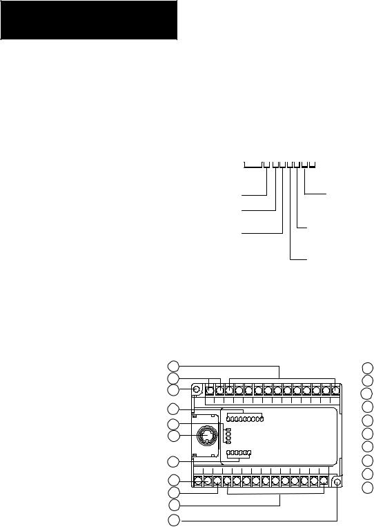
1761-L20AWA-5A |
Bulletin Number 
Base Unit
Unit I/O Count: 20
Input Signal:
A = 120V ac
B = 24V dc
 Analog I/O
Analog Circuits:
Inputs = 4
Outputs = 1
Power Supply: A = 120/240V ac B = 24V dc
Output Type:
W = Relay
B = MOSFET
A = Triac
The hardware features of the controller are:
1
2
3
4
5
6
7
8
9
10
3
|
1 |
Input terminals |
|
|
2 |
dc output terminals (or not used) |
|
|
3 |
Mounting hole |
|
|
4 |
Input LEDs |
|
IN |
5 |
Status LEDs |
|
POWER |
6 |
RS-232 communication channel |
|
RUN |
|||
FAULT |
7 |
|
|
FORCE |
Output LEDs |
||
OUT |
|||
8 |
Power supply line power |
||
|
|||
|
9 |
Ground screw |
|
|
10 |
Output terminals |
|
|
|
20142 |
1±2

Master Control Relay
Chapter 1
Installing Your Controller
A hard-wired master control relay (MCR) provides a reliable means for emergency controller shutdown. Since the master control relay allows the placement of several emergency-stop switches in different locations, its installation is important from a safety standpoint. Overtravel limit switches or mushroom head push buttons are wired in series so that when any of them opens, the master control relay is de-energized. This removes power to input and output device circuits. Refer to the figure on page 1±5.
ATTENTION: Never alter these circuits to defeat their function,
!since serious injury and/or machine damage could result.
Important: If you are using an external dc output power supply, interrupt the dc output side rather than the ac line side of the supply to avoid the additional delay of power supply turn-off.
The external ac line of the dc output power supply should be fused.
Connect a set of master control relays in series with the dc power supplying the input and output circuits.
Place the main power disconnect switch where operators and maintenance personnel have quick and easy access to it. If you mount a disconnect switch inside the controller enclosure, place the switch operating handle on the outside of the enclosure, so that you can disconnect power without opening the enclosure.
Whenever any of the emergency-stop switches are opened, power to input and output devices should be removed.
When you use the master control relay to remove power from the external I/O circuits, power continues to be provided to the controller's power supply so that diagnostic indicators on the processor can still be observed.
The master control relay is not a substitute for a disconnect to the controller. It is intended for any situation where the operator must quickly de-energize I/O devices only. When inspecting or installing terminal connections, replacing output fuses, or working on equipment within the enclosure, use the disconnect to shut off power to the rest of the system.
Important: Do not control the master control relay with the controller. Provide the operator with the safety of a direct connection between an emergency-stop switch and the master control relay.
1±3

Chapter 1
Installing Your Controller
Using Emergency-Stop Switches
When using emergency-stop switches, adhere to the following points:
•Do not program emergency-stop switches in the controller program. Any emergency-stop switch should turn off all machine power by turning off the master control relay.
•Observe all applicable local codes concerning the placement and labeling of emergency-stop switches.
•Install emergency-stop switches and the master control relay in your system. Make certain that relay contacts have a sufficient rating for your application. Emergency-stop switches must be easy to reach.
•In the following illustration, input and output circuits are shown with MCR protection. However, in most applications, only output circuits require MCR protection.
The following illustrations show the Master Control Relay wired in a grounded system.
Important: The illustrations only show output circuits with MCR protection. In most applications input circuits do not require MCR protection; however, if you need to remove power from all field devices, you must include MCR contacts in series with input power wiring.
1±4
Chapter 1
Installing Your Controller
Schematic (Using IEC Symbols)
L1 L2
 230V ac
Disconnect |
|
|
|
|
|
|
|
|
|
Fuse |
MCR |
|
|
|
|
|
230V ac |
|
|
|
|
|
I/O Circuits |
Isolation |
|
Operation of either of these contacts will |
|
|
|
Transformer |
|
remove power from the adapter external I/O |
|
|
|
X1 230V ac |
X2 |
circuits, stopping machine motion. |
|
Master Control Relay (MCR) |
|
|
|
|
|||
|
|
Emergency-Stop |
|
Start |
Cat. No. 700-PK400A1 |
|
|
|
Suppressor |
||
Fuse |
|
Push Button |
Overtravel |
Stop |
|
|
Cat. No. 700-N24 |
||||
|
|
|
Limit Switch |
|
|
|
|
|
|
|
|
|
|
|
|
|
MCR |
|
|
|
|
MCR |
Suppr. |
|
|
|
|
|
|
|
|
|
MCR |
|
|
|
230V ac |
|
|
|
I/O Circuits |
|
|
dc Power Supply. |
|
|
|
Use IEC 950/EN 60950 |
|
|
|
|
MCR |
|
|
Ð |
+ |
|
|
|
24V dc |
(Lo) |
(Hi) |
|
I/O Circuits |
Line Terminals: Connect to 230V ac |
|
|
|
terminals of controller Power Supply. |
Line terminals: Connect to 24V dc |
||
|
|
||
|
|
terminals of controller Power Supply. |
|
1±5

Chapter 1
Installing Your Controller
|
|
Schematic (Using ANSI/CSA Symbols) |
|
|
||
L1 |
|
L2 |
|
|
|
|
|
230V ac |
|
|
|
|
|
|
Disconnect |
|
|
|
|
|
|
|
|
|
|
Fuse |
MCR |
|
|
|
|
|
|
230V ac |
|
|
|
|
|
|
Output |
|
|
|
|
|
|
Circuits |
Isolation |
Operation of either of these contacts will |
|
|
|
||
Transformer |
remove power from the adapter external I/O |
|
|
|
||
|
|
circuits, stopping machine motion. |
|
|
Master Control Relay (MCR) |
|
X1 |
115V ac |
X2 |
|
|
|
|
|
|
Emergency-Stop |
|
|
Cat. No. 700-PK400A1 |
|
|
|
|
|
Suppressor |
||
|
Fuse |
Push Button |
Overtravel |
|
Start |
|
|
|
Limit Switch |
Stop |
Cat. No. 700-N24 |
||
|
|
|
|
|||
|
|
|
|
|
|
|
|
|
|
|
|
|
MCR |
|
|
|
|
|
MCR |
Suppr. |
|
|
|
|
|
|
|
|
|
|
|
|
MCR |
|
|
|
|
|
|
|
115V ac |
|
|
|
|
|
|
Output |
|
|
|
|
|
|
Circuits |
|
|
|
|
|
dc Power Supply. |
|
|
|
|
|
|
Use N.E.C. Class 2 |
|
|
|
|
|
|
for UL Listing. |
MCR |
|
|
|
|
|
|
|
|
|
|
|
|
Ð |
+ |
|
|
(Lo) |
(Hi) |
|
|
24V dc |
|
|
|
|
Output |
||
|
|
|
|
|
|
|
|
|
Line Terminals: Connect to 115V ac |
|
|
Circuits |
|
|
|
terminals of controller Power Supply. |
|
Line terminals: Connect to 24V dc |
||
|
|
|
|
|
||
|
|
|
|
|
terminals of controller Power Supply. |
|
1±6

Using Surge Suppressors
Chapter 1
Installing Your Controller
Inductive load devices such as motor starters and solenoids require the use of some type of surge suppression to protect the controller output contacts. Switching inductive loads without surge suppression can significantly reduce the lifetime of relay contacts. By adding a suppression device directly across the coil of an inductive device, you will prolong the life of the switch contacts. You also reduce the effects of voltage transients caused by interrupting the current to that inductive device, and prevent electrical noise from radiating into system wiring.
The following diagram shows an output with a suppression device. We recommend that you locate the suppression device as close as possible to the load device.
|
|
+ dc or L1 |
|
VAC/VDC |
|
|
OUT 0 |
Snubber |
|
|
|
|
OUT 1 |
|
|
OUT 2 |
|
ac or dc |
OUT 3 |
|
Outputs |
OUT 4 |
|
|
|
|
|
OUT 5 |
|
|
OUT 6 |
|
|
OUT 7 |
|
|
COM |
dc COM or L2 |
If you connect a micro controller FET output to an inductive load, we recommend that you use a 1N4004 diode for surge suppression, as shown in the following illustration.
+24V dc
VAC/VDC
OUT 0
OUT 1
OUT 2
Relay or Solid State |
OUT 3 |
|
dc Outputs |
||
|
||
OUT 4 |
||
|
OUT 5 |
1N4004 Diode |
OUT 6 |
|
OUT 7 |
24V dc common |
COM |
|
1±7
Chapter 1
Installing Your Controller
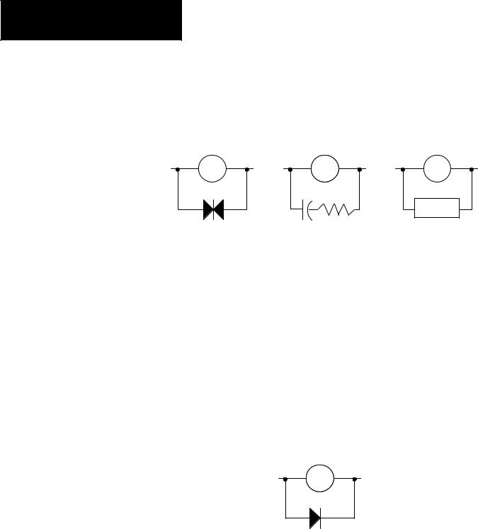
Suitable surge suppression methods for inductive ac load devices include a varistor, an RC network, or an Allen-Bradley surge suppressor, all shown below. These components must be appropriately rated to suppress the switching transient characteristic of the particular inductive device. See the table on page 1±9 for recommended suppressors.
Surge Suppression for Inductive ac Load Devices
Output Device |
Output Device |
Output Device |
|
|
Surge |
|
|
Suppressor |
Varistor |
RC Network |
|
If you connect a micro controller triac output to control an inductive load, we recommend that you use varistors to suppress noise. Choose a varistor that is appropriate for the application. The suppressors we recommend for triac outputs when switching 120V ac inductive loads are a Harris MOV, part number V175 LA10A, or an Allen-Bradley MOV, catalog number 599-K04 or 599-KA04. Consult the varistor manufacturer's data sheet when selecting a varistor for your application.
For inductive dc load devices, a diode is suitable. A 1N4004 diode is acceptable for most applications. A surge suppressor can also be used. See the table on page 1±9 for recommended suppressors.
As shown in the illustration below, these surge suppression circuits connect directly across the load device. This reduces arcing of the output contacts. (High transient can cause arcing that occurs when switching off an inductive device.)
Surge Suppression for Inductive dc Load Devices
Ð |
+ |
Output Device
Diode
(A surge suppressor can also be used.)
1±8

Chapter 1
Installing Your Controller
Recommended Surge Suppressors
We recommend the Allen-Bradley surge suppressors shown in the following table for use with Allen-Bradley relays, contactors, and starters.
Device |
Coil Voltage |
Suppressor Catalog |
|
Number |
|||
|
|
||
|
|
|
|
Bulletin 509 Motor Starter |
120V ac |
599-K04 |
|
Bulletin 509 Motor Starter |
240V ac |
599-KA04 |
|
|
|
|
|
Bulletin 100 Contactor |
120V ac |
199-FSMA1 |
|
Bulletin 100 Contactor |
240V ac |
199-FSMA2 |
|
|
|
|
|
Bulletin 709 Motor Starter |
120V ac |
1401-N10 |
|
|
|
|
|
Bulletin 700 Type R, RM Relays |
ac coil |
None Required |
|
|
|
|
|
Bulletin 700 Type R Relay |
12V dc |
700-N22 |
|
Bulletin 700 Type RM Relay |
12V dc |
700-N28 |
|
|
|
|
|
Bulletin 700 Type R Relay |
24V dc |
700-N10 |
|
Bulletin 700 Type RM Relay |
24V dc |
700-N13 |
|
|
|
|
|
Bulletin 700 Type R Relay |
48V dc |
700-N16 |
|
Bulletin 700 Type RM Relay |
48V dc |
700-N17 |
|
|
|
|
|
Bulletin 700 Type R Relay |
115-125V dc |
700-N11 |
|
Bulletin 700 Type RM Relay |
115-125V dc |
700-N14 |
|
|
|
|
|
Bulletin 700 Type R Relay |
230-250V dc |
700-N12 |
|
Bulletin 700 Type RM Relay |
230-250V dc |
700-N15 |
|
|
|
|
|
Bulletin 700 Type N, P, or PK Relay |
150V max, ac or DC |
700-N24 |
|
|
|
|
|
Miscellaneous electromagnetic devices |
150V max, ac or DC |
700-N24 |
|
limited to 35 sealed VA |
|||
|
|
||
|
|
|
Safety Considerations
Safety considerations are an important element of proper system installation. Actively thinking about the safety of yourself and others, as well as the condition of your equipment, is of primary importance. We recommend reviewing the following safety considerations.
Disconnecting Main Power
! |
ATTENTION: Explosion Hazard Ð Do not replace components |
or disconnect equipment unless power has been switched off and |
|
the area is known to be non-hazardous. |
The main power disconnect switch should be located where operators and maintenance personnel have quick and easy access to it. In addition to disconnecting electrical power, all other sources of power (pneumatic and hydraulic) should be de-energized before working on a machine or process controlled by a controller.
1±9

Chapter 1
Installing Your Controller
! |
ATTENTION: Explosion Hazard Ð Do not connect or |
|
disconnect while |
circuit is live unless area is known to be |
|
non-hazardous. |
|
|
|
|
|
Safety Circuits
Circuits installed on the machine for safety reasons, like overtravel limit switches, stop push buttons, and interlocks, should always be hard-wired directly to the master control relay. These devices must be wired in series so that when any one device opens, the master control relay is de-energized thereby removing power to the machine. Never alter these circuits to defeat their function. Serious injury or machine damage could result.
Power Considerations
Power Distribution
There are some points about power distribution that you should know:
•The master control relay must be able to inhibit all machine motion by removing power to the machine I/O devices when the relay is de-energized.
•If you are using a dc power supply, interrupt the load side rather than the ac line power. This avoids the additional delay of power supply turn-off. The dc power supply should be powered directly from the fused secondary of the transformer. Power to the dc input and output circuits is connected through a set of master control relay contacts.
Periodic Tests of Master Control Relay Circuit
Any part can fail, including the switches in a master control relay circuit. The failure of one of these switches would most likely cause an open circuit, which would be a safe power-off failure. However, if one of these switches shorts out, it no longer provides any safety protection. These switches should be tested periodically to assure they will stop machine motion when needed.
The following explains power considerations for the micro controllers.
Isolation Transformers
You may want to use an isolation transformer in the ac line to the controller. This type of transformer provides isolation from your power distribution system and is often used as a step down transformer to reduce line voltage. Any transformer used with the controller must have a sufficient power rating for its load. The power rating is expressed in volt-amperes (VA).
1±10

Chapter 1
Installing Your Controller
Power Supply Inrush
The MicroLogix power supply does not require or need a high inrush current. However, if the power source can supply a high inrush current, the MicroLogix power supply will accept it. There is a high level of inrush current when a large capacitor on the input of the MicroLogix is charged up quickly.
If the power source cannot supply high inrush current, the only effect is that the MicroLogix input capacitor charges up more slowly. The following considerations determine whether the power source needs to supply a high inrush current:
•power-up sequence of devices in system
•power source sag if it cannot source inrush current
•the effect of the voltage sag on other equipment
If the power source cannot provide high inrush current when the entire system in an application is powered, the MicroLogix powers-up more slowly. If part of an application's system is already powered and operating when the MicroLogix is powered, the source voltage may sag while the MicroLogix input capacitor is charging. A power source voltage sag can affect other equipment connected to the same power source. For example, a voltage sag may reset a computer connected to the same power source.
Loss of Power Source
The power supply is designed to withstand brief power losses without affecting the operation of the system. The time the system is operational during power loss is called ªprogram scan hold-up time after loss of power.º The duration of the power supply hold-up time depends on the type and state of the I/O, but is typically between 20 milliseconds and 3 seconds. When the duration of power loss reaches this limit, the power supply signals the processor that it can no longer provide adequate dc power to the system. This is referred to as a power supply shutdown.
Input States on Power Down
The power supply hold-up time as described above is generally longer than the turn-on and turn-off times of the inputs. Because of this, the input state change from ªOnº to ªOffº that occurs when power is removed may be recorded by the processor before the power supply shuts down the system. The user program should be written to take this effect into account.
Other Types of Line Conditions
Occasionally the power source to the system can be temporarily interrupted. It is also possible that the voltage level may drop substantially below the normal line voltage range for a period of time. Both of these conditions are considered to be a loss of power for the system.
1±11
Chapter 1
Installing Your Controller
Preventing Excessive Heat For most applications, normal convective cooling keeps the controller within the specified operating range. Ensure that the specified operating range is maintained. Proper spacing of components within an enclosure is usually sufficient for heat dissipation.
In some applications, a substantial amount of heat is produced by other equipment inside or outside the enclosure. In this case, place blower fans inside the enclosure to assist in air circulation and to reduce ªhot spotsº near the controller.
Additional cooling provisions might be necessary when high ambient temperatures are encountered.
Important: Do not bring in unfiltered outside air. Place the controller in an
|
|
|
enclosure to protect it from a corrosive atmosphere. Harmful |
||||
|
|
|
contaminants or dirt could cause improper operation or damage |
||||
|
|
|
to components. In extreme cases, you may need to use air |
||||
|
|
|
conditioning to protect against heat build-up within the |
||||
|
|
|
enclosure. |
|
|
||
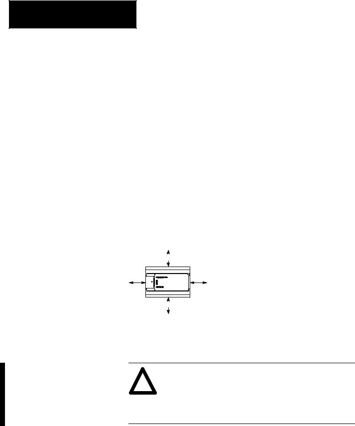
Controller Spacing |
The following figure shows the recommended minimum spacing for the |
||||||
|
controller. (Refer to appendix A for controller dimensions.) |
||||||
|
|
|
|
|
|
|
|
|
|
Top |
|
B |
|
|
|
|
Side |
|
|
Side |
|
A. Greater than or equal to 50.8 mm (2 in.). |
|
|
|
|
|
||||
|
|
|
|
||||
|
|
|
|
B. Greater than or equal to 50.8 mm (2 in.). |
|||
|
|
|
|
|
|
|
|
|
A |
|
|
A |
|
|
|
|
|
Bottom |
|
B |
|
|
|
|
|
|
|
|
|||
Mounting the Controller |
|
|
|
|
|
20142 |
|
|
|
|
|
|
|||
|
|
|
|
|
|||
This equipment is suitable for Class I, Division 2, Groups A, B, C, D or |
|||||||
|
non-hazardous locations only, when product or packaging is marked. |
||||||
ATTENTION ± Explosion Hazard:
!•Substitution of components may impair suitability for Class I, Division 2.
•This product must be installed in an enclosure. All cables connected to the product must remain in the enclosure or be protected by conduit or other means.
The controller should be mounted horizontally within an enclosure, using a DIN rail or mounting screws. Copy the template from page A±8 to help you space and mount the controller properly.
1±12

Chapter 1
Installing Your Controller
ATTENTION: Be careful of metal chips when drilling
!into the controller could cause damage. Do not drill holes above a mounted controller if the protective wrap is removed.mounting holes for your controller. Drilled fragments that fall
Use only the following communication cables in Class I, Division 2 Hazardous Locations.
Environment Classification |
Communication Cable |
|
|
|
|
Class I, Division 2 Hazardous |
1761-CBL-PM02 Series C |
|
Environment |
|
|
1761-CBL-HM02 Series C |
||
|
||
|
|
|
|
1761-CBL-AM00 Series C |
|
|
|
|
|
1761-CBL-AP00 Series C |
|
|
|
|
|
2707-NC8 Series B |
|
|
|
|
|
2707-NC9 Series B |
|
|
|
|
|
2707-NC10 Series B |
|
|
|
|
|
2707-NC11 Series B |
|
|
|
Using a DIN Rail
Use 35 mm (1.38 in.) DIN rails, such as item number 199-DR1 or 1492-DR5 from Bulletin 1492.
To install your controller on the DIN rail:
1.Mount your DIN rail. (Make sure that the placement of the controller on the DIN rail meets the recommended spacing requirements. Refer to controller dimensions in appendix A.)
2.Hook the top slot over the DIN rail.
3.While pressing the controller against the rail, snap the controller into position.
4.Leave the protective wrap attached until you are finished wiring the controller.
Side View
Protective Wrap
|
Mounting |
DIN |
Template |
Rail |
|
20146
B A |
Call-out |
Dimension |
|
|
|
DIN |
A |
84 mm (3.3 in.) |
Rail |
B |
33 mm (1.3 in.) |
C |
C |
16 mm (.63 in.) |
|
|
1±13

Chapter 1
Installing Your Controller
To remove your controller from the DIN rail:
1. Place a screwdriver in the DIN rail latch at |
Side View |
the bottom of the controller. |
|
2. Holding the controller, pry downward on |
|
the latch until the controller is released |
|
from the DIN rail. |
|
Using Mounting Screws
To install your controller using mounting screws:
Important: Leave the protective wrap attached until you are finished wiring the controller.
1. Use the mounting template from page A±8.
2. Secure the template to the mounting surface. (Make sure your controller is spaced properly.)
3.Drill holes through the template.
4.Remove the mounting template.
5.Mount the controller.
DIN
Rail
20147
Mounting
Template
Protective Wrap (remove after wiring)
Mounting Your Controller Vertically
Your controller can also be mounted vertically within an enclosure using mounting screws or a DIN rail. To insure the stability of your controller, we recommend using mounting screws.
To insure the controller's reliability, the following environmental specifications must not be exceeded.
Top |
A |
Description: |
Specification: |
|
|
||
|
|
Operating |
0°C to +40°C (+32°F to +113°F) |
|
|
Temperature |
|
Side |
Side |
Operating Shock |
9.0g peak acceleration (11±1 ms duration) |
|
A |
(Panel mounted) |
3 times each direction, each axis |
A |
Operating Shock |
7.0g peak acceleration (11±1 ms duration) |
|
|
|
||
|
|
(DIN rail mounted) |
3 times each direction, each axis |
Bottom |
A |
DC input voltage derated linearly from +30°C (30V to 26.4V). |
|
|
|
||
A.Greater than or equal to 50.8 mm (2 in.).
Note: When mounting your controller vertically, the nameplate should be facing downward.
1±14
Loading...