Rockwell Automation 1746-NO8V User Manual

Installation Instructions
SLC 500 8-Point Analog Output Module
(Catalog Numbers 1746-NO8I and 1746-NO8V)
Inside…............................................................................................page |
|
Important User Information .................................................................... |
2 |
For More Information .............................................................................. |
3 |
Hazardous Location Considerations ....................................................... |
4 |
Environnements dangereux .................................................................... |
4 |
Hardware Features ................................................................................. |
5 |
Determining Power Requirements.......................................................... |
6 |
Using an External 24V dc Power Supply (optional) ................................ |
6 |
Installation .............................................................................................. |
8 |
Wiring ................................................................................................... |
11 |
Configuration ........................................................................................ |
14 |
Specifications ....................................................................................... |
16 |
Rockwell Automation Support ................................................. |
Back Cover |
Publication 1746-IN026A-EN-P - July 2003

2 SLC 500 8-Point Analog Output Module
Important User Information
Because of the variety of uses for the products described in this publication, those responsible for the application and use of these products must satisfy themselves that all necessary steps have been taken to assure that each application and use meets all performance and safety requirements, including any applicable laws, regulations, codes and standards. In no event will Rockwell Automation be responsible or liable for indirect or consequential damage resulting from the use or application of these products.
Any illustrations, charts, sample programs, and layout examples shown in this publication are intended solely for purposes of example. Since there are many variables and requirements associated with any particular installation, Rockwell Automation does not assume responsibility or liability (to include intellectual property liability) for actual use based upon the examples shown in this publication.
Allen-Bradley publication SGI-1.1, Safety Guidelines for the Application, Installation and Maintenance of Solid-State Control (available from your local Rockwell Automation office), describes some important differences between solid-state equipment and electromechanical devices that should be taken into consideration when applying products such as those described in this publication.
Reproduction of the contents of this copyrighted publication, in whole or part, without written permission of Rockwell Automation, is prohibited.
Throughout this publication, notes may be used to make you aware of safety considerations. The following annotations and their accompanying statements help you to identify a potential hazard, avoid a potential hazard, and recognize the consequences of a potential hazard:
WARNING
Identifies information about practices or circumstances that can cause an explosion in a
!hazardous environment, which may lead to personal injury or death, property damage, or economic loss.
|
ATTENTION |
|
|
|
! |
|
Identifies information about practices or circumstances that can lead to personal injury |
|
|
or death, property damage, or economic loss. |
|
|
|
|
Identifies information that is critical for successful application and understanding of the |
|
IMPORTANT |
|
|
|
|
product. |
|
|
|
|
Publication 1746-IN026A-EN-P - July 2003

SLC 500 8-Point Analog Output Module |
3 |
|
|
For More Information
Related Publications
Table 1 List of Related Publications for 1746-NO8I and 1746-NO8V Modules
For |
Refer to this Document |
Pub. No. |
|
|
|
A more detailed description on how to install and |
SLC 500 8-Point Analog Output |
1746-UM026 |
use your 1746-NO8 module. |
Module User Manual |
|
|
|
|
A more detailed description on how to install and |
SLC 500 Modular Hardware Style User |
1747-UM011 |
use your modular SLC 500 system. |
Manual |
|
|
|
|
A more detailed description on how to install and |
SLC 500 Fixed Hardware Style |
1747-6.21 |
use your fixed SLC 500 system. |
Installation and Operation Manual |
|
|
|
|
A reference manual that contains status file data, |
SLC 500 Instruction Set Reference |
1747-RM001 |
instruction set, and troubleshooting information. |
Manual |
|
|
|
|
How to Get More Information
If you would like a manual, you can:
•download a free electronic version from the internet at www.theautomationbookstore.com
•purchase a printed manual by:
–contacting your local distributor or Rockwell Automation representative
–visiting www.theautomationbookstore.com and placing your order
–calling 1.800.963.9548 (USA/Canada) or 001.330.725.1547 (Outside USA/Canada)
Publication 1746-IN026A-EN-P - July 2003

4 SLC 500 8-Point Analog Output Module
Hazardous Location Considerations
This equipment is suitable for use in Class I, Division 2, Groups A, B, C, D or non-hazardous locations only. The following WARNING statement applies to use in hazardous locations.
WARNING |
EXPLOSION HAZARD |
|
•Substitution of components may impair suitability for Class
!I, Division 2.
•Do not replace components or disconnect equipment unless power has been switched off.
•Do not connect or disconnect components unless power has been switched off.
•All wiring must comply with N.E.C. article 501-4(b).
Environnements dangereux
Cet équipement est conçu pour être utilisé dans des environnements de Classe 1, Division 2, Groupes A, B, C, D ou non dangereux. La mise en garde suivante s’applique à une utilisation dans des environnements dangereux.
AVERTISSEMENT |
DANGER D’EXPLOSION |
|
•La substitution de composants peut rendre cet équipement
!impropre à une utilisation en environnement de Classe 1, Division 2.
•Ne pas remplacer de composants ou déconnecter l'équipement sans s'être assuré que l'alimentation est coupée.
•Ne pas connecter ou déconnecter des composants sans s'être assuré que l'alimentation est coupée.
Publication 1746-IN026A-EN-P - July 2003

SLC 500 8-Point Analog Output Module |
5 |
|
|
Hardware Features
The module contains a removable terminal block, providing connection for 8 analog output channels, which are specifically designed to interface with analog current and voltage devices. The 1746-NO8I provides eight channels of current outputs, while the 1746-NO8V provides eight channels of voltage outputs. There are no input channels on the module.
The module is configured via the programming software. There are no DIP switches.
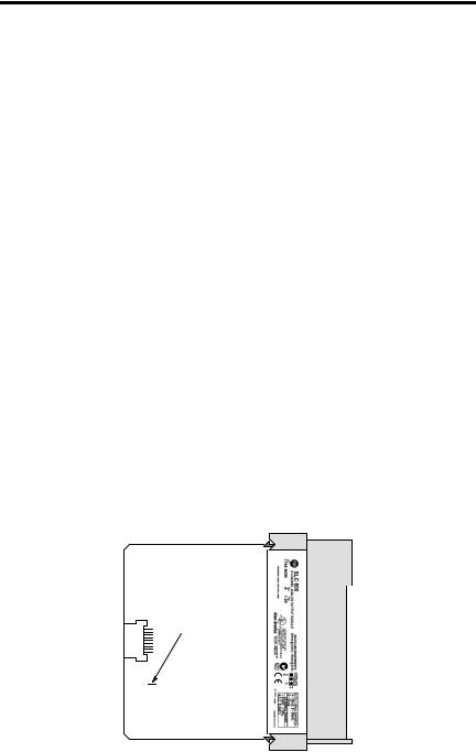
A jumper, J4, is used to select whether the 24V dc power is provided by the SLC backplane or an optional 24V dc external power supply.
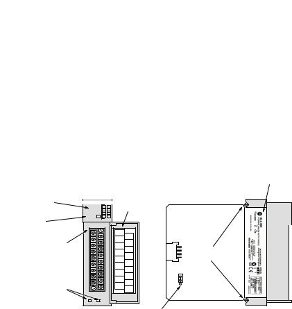
The following illustration displays the main hardware features.
Channel Status |
|
|
|
|
|
|
LEDs (Green) |
|
|
|
|
|
|
|
|
|
|
|
|
|
OUTPUT |
Door Label |
|||||
|
CHANNEL |
|
|
|
|
|
|
|
|
|
|
||
Module Status |
STATUS |
|
|
|
MODULE |
|
|
|
|
LED (Green) |
ANALOG |
|
|
|
|
|
|
|
|
|
I OUT 0 |
|
|
|
Removable |
|
ANL |
|
|
|
ANL |
|
|
|
|
I OUT 1 |
COM 0 |
|
|
Terminal Block |
I OUT 2 |
COM 1 |
|
|
I OUT 3 |
COM 2 |
|
|
|
|
|
ANL |
|
|
|
|
ANL |
|
|
|
I OUT 4 |
COM 3 |
|
|
|
|
ANL |
|
|
|
I OUT 5 |
COM 4 |
|
|
|
|
ANL |
|
|
|
I OUT 6 |
COM 5 |
|
|
|
|
ANL |
RACK |
1 |
|
I OUT 7 |
COM 6 |
|
|
|
|
ANL |
|
2 |
Cable Tie Slots |
+24 |
COM 7 |
EXT |
3 |
VDC |
DC |
|
|
|
|
|
COM |
|
|
J4 Jumper
Nameplate
Self-locking Tabs
Table 2 1746-NO8 Hardware Features
Hardware Feature |
Function |
|
|
Channel Status LED Indicators |
Displays channel operating and fault status. |
|
|
Module Status LED |
Displays module operating and fault status. |
|
|
Side Label (Nameplate) |
Provides module information. |
|
|
Removable Terminal Block |
Provides physical connection to input devices. |
|
|
Door Label |
Permits easy terminal identification. |
|
|
Cable Tie Slots |
Secures and routes wiring from the module. |
|
|
Self-Locking Tabs |
Secures module in the chassis slot. |
|
|
J4 Jumper |
Selects 24V dc power source. |
|
|
Nameplate |
Provides module information such as catalog number, backplane |
|
requirements, and output ranges. |
|
|
Publication 1746-IN026A-EN-P - July 2003

6 SLC 500 8-Point Analog Output Module
Determining Power Requirements
The module receives its power through the SLC 500 chassis backplane from the +5V dc/+24V dc chassis power supply. The +5V dc backplane supply powers the SLC circuitry, and the +24V dc backplane supply powers the module analog circuitry. The maximum current drawn by the module is shown in the table below.
Table 3 1746-NO8 Backplane Current Consumption
Specification |
1746-NO8I |
1746-NO8V |
|
|
|
Backplane Current Consumption (maximum) |
120 mA at 5V dc |
120 mA at 5V dc |
|
250 mA at 24V dc |
160 mA at 24V dc |
|
|
|
Backplane Current Consumption (maximum) |
120 mA at 5V dc |
120 mA at 5V dc |
when Using External 24V dc Power Supply(1) |
0 mA at 24V dc |
0 mA at 24V dc |
(1)The 1746-NO8I and 1746-NO8V output modules can use an external 24V dc power supply to reduce backplane loading. To use an external 24V dc power supply, you must set your module’s jumper J4 as indicated in the following section. To comply with the U.L. regulation, the external power supply must be rated N.E.C. Class 2. Do not use the 24V dc user power terminal on the chassis power supply to power the analog output module.
NOTE: The external 24V dc power supply terminal block ground connection (DC COM) is connected to the SLC power supply ground.
Add the values shown in the table above to the requirements of all other modules in the SLC chassis to prevent overloading the chassis power supply. Refer to your controller’s User Manual for power supply loading calculations and worksheets.
Using an External 24V dc Power Supply (optional)
The jumper, J4, is located in the bottom right corner of the module’s circuit board next to the power supply.
J4 jumper location
RACK
EXT
 3 2 1
3 2 1
Publication 1746-IN026A-EN-P - July 2003
 Loading...