


Bulletin 1395
Digital DC Drive
in Bulletin 2361
Motor Control Centers for Drive Systems
1250, 1650, 3000A DC
Series C
User
Manual

Important User Information
Solid-State equipment has operational characteristics differing from those of electromechanical equipment. “Safety Guidelines for the Application, Installation and Maintenance of Solid-State Controls”
(Publication SGI-1.1) describes some important differences between solid-state equipment and hard-wired electromechanical devices. Because of this difference, and also because of the wide variety of uses for solid-state equipment, all persons responsible for applying this equipment must satisfy themselves that each intended application of this equipment is acceptable.
In no event will Rockwell Automation be responsible or liable for indirect or consequential damages resulting from the use of application of this equipment.
The examples and diagrams in this manual are included solely for illustrative purposes. Because of the many variables and requirements associated with any particular installation, the Rockwell Automation cannot assume responsibility or liability for actual use based on the examples and diagrams.
No patent liability is assumed by Rockwell Automation with respect use of information, circuits, equipment, or software described in this manual.
Reproduction of the contents of this manual, in whole or in part, without written permission of Rockwell Automation is prohibited.
Throughout this manual we use notes to make you aware of safety considerations:
! |
ATTENTION: Identifies information about practices |
or circumstances that can lead to personal injury or |
|
death, property damage or economic loss. |
|
|
|
Attention statements help you to:
•identify a hazard
•avoid a hazard
•recognize the consequences
Datab is a trademark of W. H. Brady Company
CENTERLINE, PLC-5, DriveTools, and ControlNet are trademarks of Rockwell International or its subsidiaries.

Table of Contents
Preface |
Contents . . . . . . . . . . . . . . . . . . . . . . . . . . . . . . . . . . . . . . . . . |
. P-1 |
|
Who Should Use This Manual . . . . . . . . . . . . . . . . . . . . . . . . . . . |
P-1 |
|
Purpose of This Manual . . . . . . . . . . . . . . . . . . . . . . . . . . . . . . . |
P-1 |
|
Safety Precautions . . . . . . . . . . . . . . . . . . . . . . . . . . . . . . . . . . . |
P-2 |
|
Contents of this Manual . . . . . . . . . . . . . . . . . . . . . . . . . . . . . . . |
P-3 |
|
Related Documentation . . . . . . . . . . . . . . . . . . . . . . . . . . . . . . . |
P-4 |
|
Style of this Manual . . . . . . . . . . . . . . . . . . . . . . . . . . . . . . . . . . |
P-5 |
|
Terms and Abbreviations . . . . . . . . . . . . . . . . . . . . . . . . . . . . . . |
P-5 |
|
Receiving Your Drive System . . . . . . . . . . . . . . . . . . . . . . . . . . . |
P-5 |
|
Rockwell Automation Support . . . . . . . . . . . . . . . . . . . . . . . . . . . |
P-6 |
|
Local Product Support . . . . . . . . . . . . . . . . . . . . . . . . . . . . . . |
P-6 |
|
Technical Product Assistance . . . . . . . . . . . . . . . . . . . . . . . . . |
P-6 |
Chapter 1 |
Product Overview |
|
|
Contents . . . . . . . . . . . . . . . . . . . . . . . . . . . . . . . . . . . . . . . . . . |
1-1 |
|
Standard Features . . . . . . . . . . . . . . . . . . . . . . . . . . . . . . . . . . . |
1-1 |
|
Standard Options . . . . . . . . . . . . . . . . . . . . . . . . . . . . . . . . . . . . |
1-2 |
|
Hardware Overview . . . . . . . . . . . . . . . . . . . . . . . . . . . . . . . . . . |
1-3 |
|
Control Boards . . . . . . . . . . . . . . . . . . . . . . . . . . . . . . . . . . . . . . |
1-4 |
|
Main Control Board . . . . . . . . . . . . . . . . . . . . . . . . . . . . . . . . . |
1-5 |
|
Door-Mounted Programming Terminal . . . . . . . . . . . . . . . . . . |
1-6 |
|
Adapter Boards . . . . . . . . . . . . . . . . . . . . . . . . . . . . . . . . . . . |
1-6 |
|
Control/Power Interface Boards . . . . . . . . . . . . . . . . . . . . . . . . . |
1-7 |
|
Power Stage Interface Board . . . . . . . . . . . . . . . . . . . . . . . . . |
1-8 |
|
Unit Power Supply Board . . . . . . . . . . . . . . . . . . . . . . . . . . . . |
1-9 |
|
Feedback Board . . . . . . . . . . . . . . . . . . . . . . . . . . . . . . . . . . |
1-10 |
|
24V DC Power Supply . . . . . . . . . . . . . . . . . . . . . . . . . . . . . . |
1-10 |
|
Gate Interface Board . . . . . . . . . . . . . . . . . . . . . . . . . . . . . . . |
1-11 |
|
Power Components . . . . . . . . . . . . . . . . . . . . . . . . . . . . . . . . . |
1-12 |
|
Incoming Power Components . . . . . . . . . . . . . . . . . . . . . . . . |
1-12 |
|
Incoming Devices . . . . . . . . . . . . . . . . . . . . . . . . . . . . . . . |
1-12 |
|
AC Input Busbars . . . . . . . . . . . . . . . . . . . . . . . . . . . . . . . |
1-12 |
|
Main Disconnect (Optional) . . . . . . . . . . . . . . . . . . . . . . . . |
1-12 |
|
AC Line Fuses (Optional) . . . . . . . . . . . . . . . . . . . . . . . . . . |
1-12 |
|
Control and Field Power . . . . . . . . . . . . . . . . . . . . . . . . . . |
1-13 |
|
AC Line RC Suppressor (Optional) . . . . . . . . . . . . . . . . . . . |
1-13 |
Publication 2361-5.01 July 1998
toc–ii |
Table of Contents |
Armature Power Components . . . . . . . . . . . . . . . . . . . . . . . . 1-14
Armature Bridge . . . . . . . . . . . . . . . . . . . . . . . . . . . . . . . . 1-14
DC Contactor . . . . . . . . . . . . . . . . . . . . . . . . . . . . . . . . . . 1-16
Field Power Components . . . . . . . . . . . . . . . . . . . . . . . . . . . 1-17
Field Bridge . . . . . . . . . . . . . . . . . . . . . . . . . . . . . . . . . . . 1-18
Field-Pulse Transformer Board . . . . . . . . . . . . . . . . . . . . . 1-18
Chapter 2 |
Your 1250A DC Drive |
|
|
Contents . . . . . . . . . . . . . . . . . . . . . . . . . . . . . . . . . . . . . . . . . . |
2-1 |
|
Introduction . . . . . . . . . . . . . . . . . . . . . . . . . . . . . . . . . . . . . . . . |
2-1 |
|
Drive Layout . . . . . . . . . . . . . . . . . . . . . . . . . . . . . . . . . . . . . . . . |
2-2 |
|
Drive Schematics . . . . . . . . . . . . . . . . . . . . . . . . . . . . . . . . . . . . |
2-3 |
|
Symbol Reference Chart . . . . . . . . . . . . . . . . . . . . . . . . . . . . . . . |
2-6 |
|
Drive Structure . . . . . . . . . . . . . . . . . . . . . . . . . . . . . . . . . . . . . . |
2-8 |
|
Conclusion . . . . . . . . . . . . . . . . . . . . . . . . . . . . . . . . . . . . . . . . . |
2-8 |
Chapter 3 |
Your 1650A DC Drive |
|
|
Contents . . . . . . . . . . . . . . . . . . . . . . . . . . . . . . . . . . . . . . . . . . |
3-1 |
|
Introduction . . . . . . . . . . . . . . . . . . . . . . . . . . . . . . . . . . . . . . . . |
3-1 |
|
Drive Layout . . . . . . . . . . . . . . . . . . . . . . . . . . . . . . . . . . . . . . . . |
3-2 |
|
Drive Schematics . . . . . . . . . . . . . . . . . . . . . . . . . . . . . . . . . . . . |
3-3 |
|
Symbol Reference Chart . . . . . . . . . . . . . . . . . . . . . . . . . . . . . . . |
3-6 |
|
Drive Structure . . . . . . . . . . . . . . . . . . . . . . . . . . . . . . . . . . . . . . |
3-8 |
|
Conclusion . . . . . . . . . . . . . . . . . . . . . . . . . . . . . . . . . . . . . . . . . |
3-8 |
Chapter 4 |
Your 3000A DC Drive |
|
|
Contents . . . . . . . . . . . . . . . . . . . . . . . . . . . . . . . . . . . . . . . . . . |
4-1 |
|
Introduction . . . . . . . . . . . . . . . . . . . . . . . . . . . . . . . . . . . . . . . . |
4-1 |
|
Drive Layout . . . . . . . . . . . . . . . . . . . . . . . . . . . . . . . . . . . . . . . . |
4-2 |
|
Drive Schematics . . . . . . . . . . . . . . . . . . . . . . . . . . . . . . . . . . . . |
4-3 |
|
Symbol Reference Chart . . . . . . . . . . . . . . . . . . . . . . . . . . . . . . . |
4-6 |
|
Drive Structure . . . . . . . . . . . . . . . . . . . . . . . . . . . . . . . . . . . . . . |
4-8 |
|
Conclusion . . . . . . . . . . . . . . . . . . . . . . . . . . . . . . . . . . . . . . . . . |
4-8 |
Publication 2361-5.01 July 1998
|
Table of Contents |
toc–iii |
|
Chapter 5 |
Installing Your Drive |
|
|
|
Contents . . . . . . . . . . . . . . . . . . . . . . . . . . . . . . . . . . . . . . . . |
. . 5-1 |
|
|
Resources . . . . . . . . . . . . . . . . . . . . . . . . . . . . . . . . . . . . . . . . |
. 5-1 |
|
|
Physically Installing the Drive at Your Site . . . . . . . . . . . . . . . . |
. 5-2 |
|
|
Inspecting the Air Baffles . . . . . . . . . . . . . . . . . . . . . . . . . . . |
. 5-2 |
|
|
Preparing AC Input Entry . . . . . . . . . . . . . . . . . . . . . . . . . . . . . |
. 5-2 |
|
|
Installing and Configuring Your Drive . . . . . . . . . . . . . . . . . . . . |
. 5-4 |
|
|
Drive Disconnect . . . . . . . . . . . . . . . . . . . . . . . . . . . . . . . . . |
. 5-4 |
|
|
Wiring Recommendations . . . . . . . . . . . . . . . . . . . . . . . . . . . |
. 5-4 |
|
|
Drive Grounding . . . . . . . . . . . . . . . . . . . . . . . . . . . . . . . . . . |
. 5-5 |
|
|
Power Wiring . . . . . . . . . . . . . . . . . . . . . . . . . . . . . . . . . . . . |
. 5-5 |
|
|
Field Transformer . . . . . . . . . . . . . . . . . . . . . . . . . . . . . . . . . |
. 5-6 |
|
|
Installing the Field Transformer . . . . . . . . . . . . . . . . . . . . . |
. 5-7 |
|
|
Circuit Board Jumper Connections . . . . . . . . . . . . . . . . . . . . |
. 5-9 |
|
|
Armature Current Ratings . . . . . . . . . . . . . . . . . . . . . . . . . . . |
5-12 |
|
Chapter 6 |
Starting Up Your Drive |
|
|
|
Contents . . . . . . . . . . . . . . . . . . . . . . . . . . . . . . . . . . . . . . . . . |
. 6-1 |
|
|
Introduction . . . . . . . . . . . . . . . . . . . . . . . . . . . . . . . . . . . . . . . |
. 6-1 |
|
|
Voltage Measurements . . . . . . . . . . . . . . . . . . . . . . . . . . . . . . . |
. 6-1 |
|
|
Rated Armature and Field Currents . . . . . . . . . . . . . . . . . . . . . . |
. 6-2 |
|
Appendix A |
Drive Specifications |
|
|
|
Contents . . . . . . . . . . . . . . . . . . . . . . . . . . . . . . . . . . . . . . . . . |
. A-1 |
|
|
General Specifications . . . . . . . . . . . . . . . . . . . . . . . . . . . . . . . |
. A-1 |
|
|
Unit Specifications . . . . . . . . . . . . . . . . . . . . . . . . . . . . . . . . . . |
. A-2 |
|
|
Electrical Specifications . . . . . . . . . . . . . . . . . . . . . . . . . . . . . . |
. A-3 |
|
|
Power Dissipation . . . . . . . . . . . . . . . . . . . . . . . . . . . . . . . . . . |
. A-4 |
|
|
Circuit Breaker Settings . . . . . . . . . . . . . . . . . . . . . . . . . . . . . . |
. A-5 |
|
|
Circuit Breaker Derating . . . . . . . . . . . . . . . . . . . . . . . . . . . . . . |
. A-6 |
|
|
Input Busbars . . . . . . . . . . . . . . . . . . . . . . . . . . . . . . . . . . . . . . |
. A-7 |
|
|
Air Baffle Layouts . . . . . . . . . . . . . . . . . . . . . . . . . . . . . . . . . . . |
. A-9 |
|
Publication 2361-5.01 July 1998

toc–iv Table of Contents
Appendix B Catalog Numbers and Spare Parts Kits
Contents . . . . . . . . . . . . . . . . . . . . . . . . . . . . . . . . . . . . . . . . . . B-1
Understanding Catalog Numbers . . . . . . . . . . . . . . . . . . . . . . . . B-1
Determining Catalog Numbers . . . . . . . . . . . . . . . . . . . . . . . . B-1
DC Drive Catalog Numbers . . . . . . . . . . . . . . . . . . . . . . . . . . . . . B-3
DC Drive Spare Parts Kits . . . . . . . . . . . . . . . . . . . . . . . . . . . . . . B-6
What Does a Spare Parts Kit Include? . . . . . . . . . . . . . . . . . . . B-6
Which Table Do I Use? . . . . . . . . . . . . . . . . . . . . . . . . . . . . . . B-6
Significance of Level Numbers . . . . . . . . . . . . . . . . . . . . . . . . B-6
Definition of Terms Used to Describe "Qty in Kit" . . . . . . . . . . B-7
Catalog Number Description . . . . . . . . . . . . . . . . . . . . . . . . . . B-7
Publication 2361-5.01 July 1998

Preface
Preface
Contents
Who Should Use This Manual
Purpose of This Manual
This preface will introduce you to the contents and purpose of this manual. The following topics will be discussed in this preface:
Topic |
Page |
Who Should Use This Manual |
P-1 |
|
|
Purpose of This Manual |
P-1 |
|
|
Safety Precautions |
P-2 |
|
|
Contents of This Manual |
P-3 |
|
|
Related Documentation |
P-4 |
|
|
Style of This Manual |
P-5 |
|
|
Terms and Abbreviations |
P-5 |
|
|
Receiving Your Drive System |
P-5 |
|
|
Rockwell Automation Support |
P-6 |
|
|
This manual is intended for those who are responsible for installing or operating a Rockwell Automation high-horsepower 1395 drive.
If you do not have a basic understanding of this unit, please refer to the drive documentation, or contact your local Rockwell Automation Drive Systems representative for more information before using this product.
This manual is a supplement to Publication 1395-5.40, titled 1395 Digital DC Drive–User Manual . This manual will cover:
•hardware overviews
•specifications
•installation instructions
•configuration and setup information
•spare parts
Publication 2361-5.01 July 1998

P-2
Safety Precautions
The following general precautions apply to Bulletin 2361 drive system lineups:
! |
ATTENTION: Only those familiar with the drive |
system, the products used in the system, and the |
|
associated machinery should plan or implement the |
|
|
installation, startup, and future maintenance of the |
|
system. Failure to comply can result in personal injury |
|
and/or equipment damage. |
ATTENTION: Verify that all sources of AC and DC power are deenergized and locked out or tagged out in accordance with the requirements of ANSI/NFPA 70E, Part II.
ATTENTION: The system may contain stored energy devices. To avoid the hazard of electrical shock, verify that all voltage on capacitors has been discharged before attempting to service, repair, or remove a drive system or its components. You should only attempt the procedures in this manual if you are qualified to do so and are familiar with solid-state control equipment and the safety procedures in ANSI/NFPA 70E.
ATTENTION: An incorrectly applied or incorrectly installed drive system can result in component damage and/or a reduction in product life. Wiring or application errors–such as undersizing the motor, inco rrect or inadequate AC supply, and excessive ambient temperatures–can result in the malfunction of hte drive equipment.
ATTENTION: This drive system contains parts and assemblies that are sensitive to ESD (electrostatic discharge). Static control precautions are required when installing, testing, or repairing this assembly. Component damage can result if ESD control procedures are not followed. If you are not familiar with static control procedures, refer to Rockwell Automation publication 8000-4.5.2, Guarding Against Electrostatic Damage, or another adequate handbook on ESD protection.
Publication 2361-5.01 July 1998

P-3
Contents of this Manual
Chapter |
Title |
Contents |
|
Preface |
Purpose, background, and scope of this manual |
|
|
|
1 |
Product Overview |
Theory of operation, features, and standard options |
|
|
|
2 |
Your 1250A DC Drive |
Features, components, and schematics of the 1250A drive (R-frame) |
|
|
|
3 |
Your 1650A DC Drive |
Features, components, and schematics of the 1650A drive (S-frame) |
|
|
|
4 |
Your 3000A DC Drive |
Features, components, and schematics of the 3000A drive (T-frame) |
|
|
|
5 |
Installing Your Drive |
Installation procedures and connection details |
|
|
|
6 |
Starting Up Your Drive |
Information for starting up your drive |
|
|
|
A |
Drive Specifications |
Electrical, environmental, and operational specifications |
|
|
|
B |
Catalog Numbers and Spare Parts Kits |
Explanation of catalog numbers and listings of spare part kits |
|
|
|
Publication 2361-5.01 July 1998

P-4
Related Documentation
Several of the following documents will be needed to understand and install your drive and its components. To obtain a copy of any Rockwell Automation publication, please contact your local Rockwell Automation office or distributor.
For |
Read This Document |
Document Number |
|
Information on the 1395 digital DC drives |
Bulletin 1395 Digital DC Drive–User Manual |
1395-5.40 |
|
Troubleshooting information for 1395 drives |
Bulletin 1395 Digital DC Drive–Troubleshooting |
1395-5.45 |
|
|
Manual |
|
|
Using the Bulletin 1300 programming terminal |
Bulletin 1300 Programming Terminal–User Manual |
1300-5.5 |
|
PLC-5™ information |
PLC-5 Controllers Brochure |
1785-1.2 |
|
Additional Information on joining and splicing |
Joining and Splicing Vertical Sections–Instructions |
2100-5.1 |
|
together MCCs |
|
|
|
Details on receiving, handling, and storing |
Receiving, Handling, and Storing Motor Control |
2100-5.5 |
|
MCCs |
Centers–Instructions |
|
|
Provides procedures for those tasks that need |
Bulletin 2300 Installation Manual |
2300-5.1 |
|
to be done at the customer’s site before system |
|
|
|
start up |
|
|
|
Information and installation instructions for the |
Bulletin 1395 Node Adapter Board–Installation and |
1395-5.9 |
|
1395 Node Adapter Board |
Operation Manual |
|
|
Information and installation instructions for the |
1395 Discrete Adapter Board–Installation and |
1395-5.12 |
|
1395 Discrete Adapter Board |
Operation Manual |
|
|
Information and installation instructions for the |
Bulletin 1395 ControlNet Communication Board– |
1395-5.37 |
|
1395 ControlNet Communication Board |
User Manual |
|
|
Information and installation instructions for the |
Bulletin 1395 Multi-Communication |
1395-5.33 |
|
1395 Multi-Communication Board |
Board–Hardware/Software Reference Manual |
|
|
Information and installation instructions for the |
Bulletin 1395 Digital Reference Adapter |
1395-5.55 |
|
1395 Digital Reference Adapter Board |
Board–Hardware/Software Reference Manual |
|
|
A description of DriveTools™ software |
DriveTools Software Brochure |
9303-1.0 |
|
Information on FD86N enclosures |
FD86N Drive Systems Enclosure Hardware– |
S-3062 |
|
|
Installation Manual |
|
|
Standards for electrical procedures (wiring |
National Electrical Code |
ANSI / NFPA 70 |
|
sizes, grounding, etc.) |
(Published by the National Fire Protection |
|
|
|
Association of Boston, MA) |
|
|
An article on safety procedures |
Standard for Electrical Safety Requirements for |
ANSI / NFPA 70E |
|
|
Employee Workplaces |
|
|
A complete listing of current documentation, |
Allen-Bradley Publication Index |
SD499 |
|
including ordering instructions. Also indicates |
|
|
|
whether the documents are available on CD- |
|
|
|
ROM or in multi-languages |
|
|
|
A glossary of industrial automation terms and |
Industrial Automation Glossary |
AG-7.1 |
|
abbreviations |
|
|
|
Publication 2361-5.01 July 1998
P-5
Style of this Manual |
The following conventions are used throughout this manual: |
•‘ATTENTION’ statements, preceded with the symbol shown,
 indicate a circumstance that could could lead to personal injury, ! death, damage to property, or economic loss
•‘Important ’ statements indicate key information for successfully performing procedures and understanding the product
&• Reference statements, preceded with the symbol shown, lead you
to other resources of information and instruction
•Horsepower ratings are provided at the start of each drive chapter
•Schematic and layout component abbreviations are explained in component reference charts in each drive chapter
Terms and Abbreviations
The following terms and abbreviations are used in this manual:
Term |
Definition |
armature |
rotating part of a motor |
|
|
bridge |
assembly for power (AC/DC) conversion |
|
|
busbar |
a large tin-plated copper conductor, used for high-power input and output |
|
|
feedback |
status signals/voltages sent from components or external devices |
|
|
gate |
an electrical switch |
|
|
MCC |
motor control center, an enclosure for drive systems |
|
|
MOV |
metal-oxide varistor, used for voltage spike protection |
|
|
SCR |
silicon-controlled rectifier, used in power conversion |
|
|
snubber |
a resistor/capacitor assembly, used for limiting excess voltage |
|
|
Receiving Your Drive System
You, the Customer, are responsible for thoroughly inspecting the equipment before accepting the shipment from the freight company. Check the item(s) that you receive against your purchase order. If any items are obviously damaged, do not accept the delivery until the freight agent has noted the damage on the freight bill. Should you discover any concealed damage during unpacking, you are responsible for notifying the freight agent. In such a case, leave the shipping container intact and request that the freight agent make a visual inspection of the equipment.
Publication 2361-5.01 July 1998

P-6
Rockwell Automation Support
Rockwell Automation offers support services worldwide, with Sales/ Support Offices, authorized distributors, and authorized Systems Integrators located throughout the United States, plus Rockwell Automation representatives in every major country in the world.
Local Product Support
Please contact your local Rockwell Automation representative for:
•sales and order support
•product technical training
•warranty support
•support service agreements
Technical Product Assistance
If you need to contact us for technical assistance, please review the product and troubleshooting information in this manual first.
For the quickest possible response, please have the catalog numbers of your products ready when you call.
Publication 2361-5.01 July 1998

Chapter 1
Product Overview
Contents
Standard Features
The high-horsepower line of 1395 DC drives are Bulletin 1395 regulator products, with a high-horsepower silicon-controlled rectifier (SCR) bridge, packaged in a Bulletin 2361 CENTERLINE™ motor control center, providing DC power for your high-horsepower applications.
This first chapter will introduce you to the high-horsepower Bulletin 1395 drive covering these topics:
Topic |
Page |
Standard Features |
1-1 |
|
|
Standard Options |
1-2 |
|
|
Hardware Overview |
1-3 |
|
|
Control Components |
1-4 |
|
|
Control/Power Interface Components |
1-7 |
|
|
Power Components |
1-12 |
|
|
The high-horsepower Bulletin 1395 drive includes the following standard features:
•NEMA Class I construction
•High AIC instantaneous trip circuit breaker or line fuses for the AC input, armature cell fuses, and a DC output contactor
•a six pulse, full-wave rectified armature converter
•43A single-phase field regulator
•regenerative (1250, 1650, and 3000A) or non -regenerative (1250 and 1650A units only)
•6:1 constant horsepower range
•digital control for current, velocity, and configuration
•auto tuning for velocity loop, current loop, field flux table
Publication 2361-5.01 July 1998
1-2 |
Product Overview |
Standard Options
•programmable functions (independent acceleration/deceleration adjustment, preset speeds, current limit, tapered current limit, tach loss recovery, system reset)
•protective features (instantaneous overcurrent, motor overload, feedback loss, field loss, field economy, tach loss recovery, system reset)
•CENTERLINE Bulletin 2361 Motor Control Center enclosure
The following options are available for the high-horsepower 1395 drives:
•115V AC discrete adapter board
•24V DC dis crete adapter board
•node adapter board
•multi-communications adapter board
•door-mounted DHT or EHT programming terminal
•‘start/running’ and ‘cl ear fault/drive faulted’ door-mounted illuminated pushbuttons
•‘drive stop’, ‘hardwired stop’, ‘jog forward’, and ‘jog reverse’ door-mounted pushbuttons
•‘power on’ door-mounted pilot light
•door-mounted speed potentiometer
•1-2-3 speed selector
•blower starter (NEMA, IEC)
•90A single-phase field regulator
•control circuit transformer
•top-hat input enclosure (standard for 3000A drive)
•line RC suppressor
•AC power thru bus
Note: Additional options are listed in Appendix B.
Publication 2361-5.01 July 1998

Product Overview |
1-3 |
Hardware Overview
The hardware components shown in form the high-horsepower 1395 DC drive. These drive components can be broken down into the following three categories:
Hardware |
Description |
Control |
Controls the drive system and interfaces with external devices |
Control/Power Interface Interfaces the control components with the power components
Power Converts AC input to a DC supply for the motor
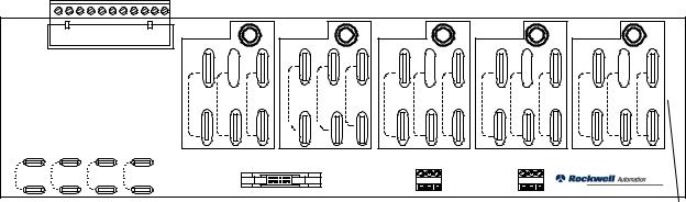
Figure 1.1
Drive Components
3-Phase AC Power
J7 J6
J5
Main Control Board
J2
J4 J1
Programming
Terminal
DHT/DMT
TB3
|
|
|
|
Circuit Breaker |
|
|
|
|
Field Transformer |
|
|
|
|
(Only Used For AC Inputs of |
|
|
|
|
575 and 660V AC) |
|
|
Control |
|
TB8 |
|
|
Transformer |
Fuses |
|
|
Unit |
|
|
|
|
|
|
|
|
|
Power Supply |
|
AC Line Voltage Feedback |
|
|
|
|
|
|
|
J1 |
24V DC |
|
|
|
|
Feedback |
|
|
|
|
Power Supply |
Armature Current Feedback |
|
|
|
|
MOVs |
|
|
J7 |
Feedback Board |
|
|
|
|
|
|
|
J8 |
J2 |
J40 |
Field Current Feedback |
|
|
|
|||
|
Power Stage |
|
Armature DC Voltage Feedback |
|
|
|
|
|
|
Interface Board |
|
|
|
|
J9
|
J3A |
Gate |
Armature |
|
|
|
|
J6 |
- |
Interface |
3-Phase |
|
Field PT & |
||
J3D |
Pulse |
Single-Phase |
|||||
|
Board |
Snubber |
|||||
|
|
Transformer |
SCR Armature |
SCR Field |
|||
|
|
|
|
||||
|
|
|
Bridge |
Bridge |
J1 |
||
|
|
|
Boards |
||||
|
|
|
|
|
|
- |
|
|
+ |
|
|
M1 |
|
|
|
|
TB7 |
|
Motor |
|
|
A2 |
Armature |
A1 |
|
Encoder Feedback |
|
|
|
F1 |
F2 |
F3 |
F4 |
Encoder |
|
|
|
CONTROL |
CONTROL/POWER INTERFACE |
POWER |
Publication 2361-5.01 July 1998
1-4 |
Product Overview |
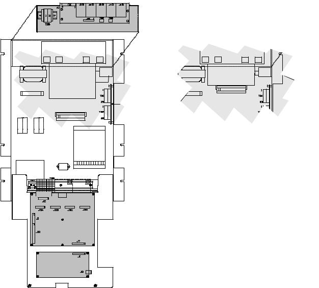
Control Boards
The control boards manage and control the system, processing status information from system components and commanding drive components and activities.
Figure 1.2
Control Boards
M ain C ontrol B oa rd |
A dapter B oards |
Feedb ac k Board |
Feed b a ck B oard |
||
|
M a in Con trol Board |
||
|
(beh in d ad ap ter board s) |
||
C H 1 |
|
|
|
F C T |
|
|
|
F1 4 F 1 5 |
Discrete o r |
|
|
Digital |
Com m u nic atio n |
||
|
|||
|
Refere nc e |
Ad apter B oard |
|
|
Ad ap te r Board |
(Po rt B ) |
|
|
(P ort A ) |
|
|
|
O P TIO N AL |
O P TIO N A L |
|
|
|
M P |
|
|
|
24 V D C S u pp ly |
|
M ain Control |
|
|
|
Boa rd |
|
|
|
Publication 2361-5.01 July 1998
Product Overview |
1-5 |
Main Control Board
The main control board is the center of the control processing. This board has a number of test points and jumpers that are used during startup and troubleshooting. Refer to the troubleshooting manual for more information on test points and jumpers.
Figure 1.3
Main Control Board
J 2 |
C on nection to P ow er |
|
|
J 4 |
|
|
J 5 |
|||
|
|
|
C onne ction to |
|
|
C on nection to P ow er |
||||
|
S tag e Inte rface B oard |
|
|
P rogram m ing Term in al |
|
S tag e Inte rface B oard |
||||
|
|
TP 2 |
|
|
|
TP 5 |
|
|
|
|
|
|
TP 1 3 |
1 |
2 |
3 |
|
TP 9 |
T P 6 |
|
|
|
|
TP 1 2 |
|
|
|
|||||
|
TP 1 1 |
J 1 0 |
|
|
|
|
||||
|
|
|
|
|
|
|
|
|
||
|
|
TP 1 5 |
|
|
|
|
|
TP 2 1 |
|
|
C onnection |
|
|
|
|
|
|
|
|||
|
1 |
2 |
3 |
|
T P 24 |
|
|
|
||
T o |
|
TP 2 3 |
J 9 |
|
|
|
|
|||
|
|
|
|
|
|
|
|
|||
E ncoder |
|
|
|
|
|
TP 25 |
|
|
||
|
TP 3 2 |
|
|
|
|
|
T P2 7 TP 26 |
|||
|
|
1 2 3 |
|
|
|
|
||||
|
|
|
|
|
TP 3 3 |
TP 3 4 |
T P 28 |
|||
|
|
TP 3 5 |
J 8 |
|
|
|||||
|
|
|
|
|
|
|
|
T P3 1 TP 29 |
||
|
|
|
|
|
|
|
|
|
||
T P 17 TP 8 TP 3 9
T P4 2
T P5 0
V P
TP 4 5
TP 4 6
S P
T P3 8 TP 3 0
TP 1 9
|
|
C P |
TP 1 0 |
|
|
|
|
|
T P 43 |
|
T P 41 |
|
|
|
|
TP 1 |
|
|
T P 20 |
T P4 7 |
TP 4 4 |
|
T P2 0 |
|
|
|
TP 49 |
|
|
|
T P 58 |
|
1 |
J1 4 |
|
2 |
|
|
3 |
|
T P 54 |
TP 5 3 |
TP 5 8 |
ISO + 1 2 V |
IG N D |
IS O + 5 V |
TP 5 1 T P 52 TP 5 6 T P 55 T P5 7 |
|
|
+ 5 V D GN D -1 2 V + 1 2 V A G N D |
|
|
|
P ort A |
|
|
|
P ort B |
J7 |
(To A dapter Board) |
|
J6 |
|
(To A dapter Board ) |
|
|
|
|||
|
|
|
|
|
|
|
|
|
|
|
|
Publication 2361-5.01 July 1998
1-6 |
Product Overview |
Door-Mounted Programming Terminal
The door-mounted Bulletin 1300 programming terminal is the interface module used to program and control the drive (typically used in standalone applications). This terminal has an LCD screen and a 24-key environment-safe keypad.
Adapter Boards
Optional adapter boards (such as the discrete adapter board, digital reference adapter board, node adapter board, and multicommunication adapter board) connect the drive to networks and provide I/O capabilities.
&Adapter board and programming terminal publications are listed in the preface of this manual. Please refer to the appropriate manuals for more information.
Publication 2361-5.01 July 1998
Product Overview |
1-7 |
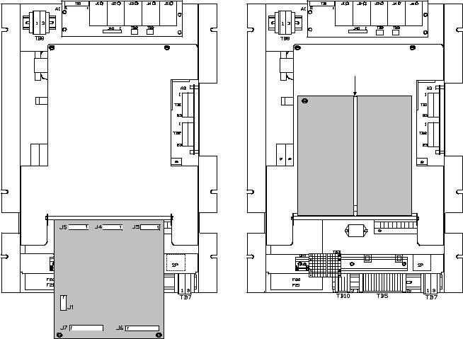
Control/Power Interface Boards
Control/power interface boards are used to provide a link between control boards (which are responsible for managing the drive), and power components (which are closely associated with the actual drive hardware and operations).
The following items are used to provide this interfacing:
•power stage interface board
•unit power supply board
•feedback board
These items are located on the control module in the disconnect bay of the drive, and are arranged as shown below. Accessibility to the power stage interface board and the unit power supply is gained by lowering the front panel.
Figure 1.4
Control/Power Interface Boards
Feedb ack B o ard |
|
C H1 |
|
F C T |
F1 4 |
F1 6 |
F1 5 |
F4 |
F2 0
F2 1
Field Pu lse T ra nsform er an d S n u bb er Board
2 M O V
3 M O V
43 A F ield B ridg e
G ate In terfac e
B oard
FA N 4
24 V D C S u p ply
1 |
2 3 |
4 |
5 |
7 |
8 |
9 |
1 0 |
M P
A lterna te Field B ridge |
|
Co nfiguratio n |
|
C H1 |
|
Op tion 1 4FX |
2M OV |
3M OV |
|
Fie ld B rid g e |
|
F C T |
|
FA N 4 |
|
J9
T B 1
Po w er S ta ge Interfa ce B oa rd
Unit P ow er Supply B o ard
Publication 2361-5.01 July 1998
1-8 |
Product Overview |
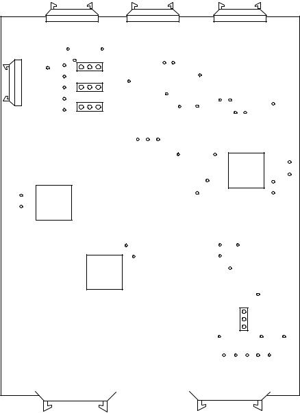
Power Stage Interface Board
The power stage interface board is used as the chief interface between the main control board and other boards of the system. This board is responsible for distributing power and control signals to and from the main control board, gate interface board, field-pulse transformer board, feedback board, and unit power supply. Refer to Figure 1.1 to see how this board is connected in the drive.
Figure 1.5
Power Stage Interface Board
|
|
|
|
C o nn e ctio n to U n it P o w e r |
|
|||||||
|
|
|
|
S up ply a nd T E |
|
|||||||
|
|
|
|
|
|
|
|
|
|
|
|
|
|
|
|
|
|
|
|
|
|
|
|
|
|
J 8 |
|
|
|
|
|
|
J 9 |
|
|
|||
|
|
|
|
|
|
|
|
|
|
|
||
|
|
|
|
|
|
|
|
|
|
|
||
|
|
C o nn e ctio n to M a in Co n tro l Bo a rd |
|
|
T B 1 |
|
C o nn e ctio n to M a in Co n tro l Bo a rd |
|
||||
|
|
|
|
|
|
|
|
|
|
|||
|
|
|
|
|
|
|
|
|
|
|
|
|
|
|
|
|
|
|
|
|
|
|
|
|
|
J 6 |
|
J 2 |
|
|
Co n ne c tio n to |
Co n ne ctio n to |
|||
|
|
|||
|
F ie ld Tra n sfo rm e r |
|
F e e db a ck B o a rd |
TP 1
(+ 2 4 V )
|
|
|
|
|
|
|
|
|
|
|
J 3D |
|
J 3C |
J 3B |
|
|
J3 A |
|
|
||
|
|
C o nn e ctio ns to |
|
|
|
|
|
|
||
|
|
G a te Inte rfa ce B o a rd |
|
|
|
|
|
|
||
|
|
|
|
|
|
|
C o nn e ctio n to |
|
|
|
|
|
|
|
|
|
|
|
|
||
|
|
|
|
|
|
M a in C o nta cto r, P ilo t R e la y, |
|
|
||
|
|
|
|
|
|
a nd U nit P o w e r S up ply |
|
|
||
|
|
|
|
|
|
|
|
|
|
|
T P 2
J1
J 11
TP 3
TP 8 |
T P 7 |
T P 6 |
T P 5 |
J 12 |
|
||||
(-1 2 V) |
(G nd ) |
(+ 1 2 V ) |
(+ 5 V) |
|
|
|
|
T P 9 |
C o nn e cte d to T B 3 |
|
|
|
|
(S ta nd a rd In te rfac e ) |
|
|
|
C o n ne ctio n to |
|
|
|
|
U n it P ow e r S u pp ly |
|
J 7
J1 0
&The test points and jumpers shown in the diagram are used for startup and troubleshooting procedures. Refer to the troubleshooting manual for more information on test points and jumpers.
Publication 2361-5.01 July 1998
Product Overview |
1-9 |
The power stage interface board provides the following services between the main control board and other boards in the system:
•furnishes DC control power to the main control board (from the unit power supply)
•provides 3-phase line synchronization signals to the main control board
•accepts signals from the main control board and produces the logic and drivers for armature and field-pulse transformers
•accepts signals for start/stop logic, protection I/O, and drivers for operating the main DC contactor
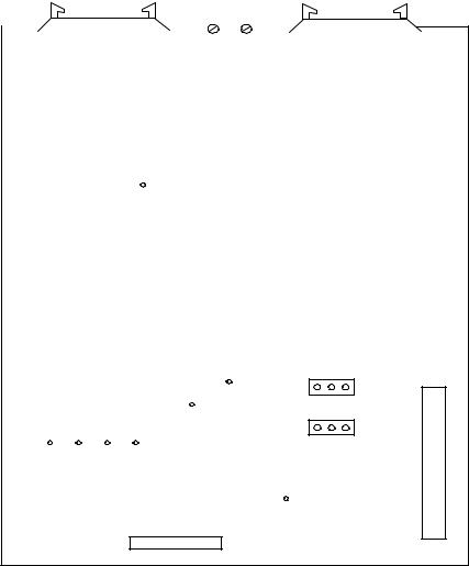
Unit Power Supply Board
The unit power supply board converts 115V AC input into regulated +5V DC and ±12V DC control voltages. These control voltages are routed through the power stage interface board to provide power to all the printed circuit boards.
Figure 1.6
Unit Power Supply Board
Con nection to Power S tag e Interfa ce Board
(+ 5V an d ±12V)
1
2
J1 3
F1
Con nection to Pow er Stag e Interface Board (115V A C)
Publication 2361-5.01 July 1998
1-10 |
Product Overview |
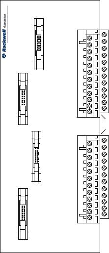
Feedback Board
The feedback board receives status information from the drive components, scales it to a signal level, and supplies it to the main control board (through the power stage interface board).
Figure 1.7
Feedback Board
TB 1 |
|
|
|
|
A |
|
|
B |
|
|
C |
|
|
VA+ |
|
|
VA- |
|
|
|
|
|
|
|
|
|
|
|
|
|
|||||
|
|
|
|
|
|
|
|
|
|
|
|
|
|
|
|
|
|
|
|
|
150 VAC |
301VAC |
576VAC |
150 VAC |
301VAC |
576VAC |
150 VAC |
301VAC |
576VAC |
150 VAC |
301VAC |
576VAC |
150 VAC |
301VAC |
576VAC |
|
|
|
TO |
TO |
TO |
||||||||||||
|
|
|
TO |
TO |
TO |
TO |
TO |
TO |
TO |
TO |
TO |
TO |
TO |
TO |
|||
|
|
|
300 VAC |
575VAC |
690VAC |
300 VAC |
575VAC |
690VAC |
300 VAC |
575VAC |
690VAC |
300 VAC |
575VAC |
690VAC |
300 VAC |
575VAC |
690VAC |
|
|
|
|
|
|
||||||||||||
(1) |
(2) |
(3) |
(4) |
J4 0 |
|
|
|
|
T B 2 |
|
|
T B 3 |
|
|
|
|
|
|
|
|
|
|
|
|
|
|
|
|
|
|
|
|
|
|
|
|
|
|
|
|
|
|
|
|
FEEDBACK BURDEN RESISTOR |
FEEDBACK BURDEN RESISTOR ARMATURE |
|
|
|
||||
Ju m p er Conn ection |
To Pow er S tag e |
N ot U sed |
Ju m p er C onn ections |
(Field Current) |
In terfac e Board |
|
(A C In pu t V oltag e) |
The feedback board has terminals for the 3-phase AC inputs (A, B, and C) and for the armature power (VA+ and VA-), a series of jumper connections to adjust for AC input voltage, jumper connections for the field current, a bus connection to the power stage interface board, two terminals blocks for placing burden resistors in parallel to the circuit, and a Phoenix connection terminal block connected to other drive components.
Note: Jumper settings are defined in the installation chapter of this manual.
24V DC Power Supply
There are three 24V DC power supply units that may be installed in the drive. There is a feedback board supply, an optional air flow sensor supply, and an optional control board supply (used to power an optional adapter board). These supply units are fed from the 115V AC control power circuit.
Publication 2361-5.01 July 1998
Product Overview |
1-11 |
Gate Interface Board
The gate interface board is the junction between the power stage interface board and the individual armature-pulse transformer boards. This board has four bus connections to the power stage interface board and four Phoenix terminal blocks distributing signals to the armature-pulse transformer boards.
Figure 1.8
Gate Interface Board
C onne ctions to P ow e r Stage
Inte rface Bo ard
TB1
J4
J3
J2
J1
TB2
Co nne ction s to Arm a ture-P ulse Tra nsfo rm e r Bo ards
Publication 2361-5.01 July 1998
1-12 |
Product Overview |
Power Components
This section will break down and define the incoming power, armature power, and field supply components.
Incoming Power Components
Incoming Devices
The 1250 and 1650A DC drives are intended to be used straight from the customer-supplied, power controlled incoming lines, without any additional isolation transformer or line chokes (however, adding either of these would increase isolation to other equipment on the power lines).
The 3000A DC drive does not require an isolation transformer or line reactors if it is the only equipment on the power lines. However, if it shares power with other equipment on the same power lines, it will be necessary to use either line reactors or an isolation transformer ahead of the drive.
The system designer needs to provide proper circuit impedence to limit the short circuit currents according to the breaker derating charts given in Appendix A.
Some drives may require an output inductor in series with the armature, especially for older machines which do not have enough internal inductance for a proper armature commutation process.
AC Input Busbars
Tin plated busbars are supplied for all input connections through the top of the disconnect bay. Busbar dimension diagrams are given in Appendix A.
Main Disconnect (Optional)
A 3-phase circuit breaker can be supplied on the incoming line for each high-horsepower drive. Appendix A lists circuit breaker specifications, and shows diagrams of the circuit breakers settings for the 1250, 1650, and 3000A DC drives.
AC Line Fuses (Optional)
AC line fuses can be supplied for the 3-phase incoming power.
Note: Units require either a main disconnect or AC line fuses.
Publication 2361-5.01 July 1998
Product Overview |
1-13 |
Control and Field Power
The first (L1) and third (L3) phase of the incoming power are tapped off and fused to provide single-phase AC power to the primary of control power transformer (115V AC), field supply circuit (460V AC maximum), and 24V DC power supply.
Note: For drives using a 575 or 660V AC input, a step-down transformer will be required for the field supply circuit (see Figure 1.12).
AC Line RC Suppressor (Optional)
The optional AC line RC suppressor is a device used for limiting line voltage spikes in drives when the medium voltage source to the primary of the distribution transformer is switched. The option is offered for a distribution transformer primary voltage of 2300V or greater.
Publication 2361-5.01 July 1998
1-14 |
Product Overview |
|
|
|
|
|
|
|
|
|
|
|
|
|
|
|
Armature-Pulse |
|
|
|
|
|
|
|
Transformer Board |
SNUBBER |
|
|
|
|
|||
|
|
|
|
|
|
||
|
|
|
|
|
|
||
|
|
|
|
|
|
|
|
|
|
|
|
|
|
|
|
|
|
|
|
|
|
|
|
|
|
|
|
|
|
|
|
|
|
|
|
|
|
|
|
|
|
|
|
|
|
|
|
3-Phase AC Input
Armature-Pulse
Transformer Board
SNUBBER
Armature Power Components
The armature power components work together to convert the 3- phase AC input to a DC output used for powering your motor armature.
The following items make up the armature power circuitry:
•armature bridge (and its subordinate components)
•cell fuses
•gate boards
•DC contactor
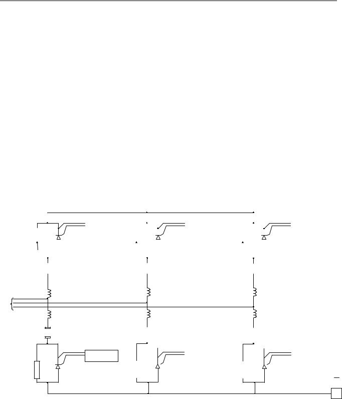
Armature Bridge
The armature bridge is designed to convert incoming AC power to DC power. The non-regenerative bridge is shown in Figure 1.9. Cell fuses protect the thyristors in the event of a bridge failure.
Figure 1.9
Armature Bridge (Non-Regenerative)
|
|
|
|
|
|
|
|
|
|
|
|
|
|
Main |
|
|
|
|
||||
|
|
|
|
|
|
|
|
|
|
|
|
|
|
Contactor |
|
|
|
|
||||
|
|
|
|
|
|
|
|
|
|
|
|
|
|
|
|
|
|
|
|
|
|
|
|
|
|
|
|
|
|
|
|
|
|
|
|
|
|
|
|
|
|
|
|
|
|
|
|
|
|
|
|
|
|
|
|
|
|
|
|
|
|
|
|
|
|
|
||
|
|
|
|
|
|
|
|
|
|
|
|
|
|
|
|
|
|
|
A1 |
|
||
|
|
|
|
|
|
|
Armature-Pulse |
|
|
|
|
|
|
|
|
Armature-Pulse |
|
|
|
|||
|
|
|
|
|
|
|
Transformer Board |
|
|
|
|
|
|
|
|
Transformer Board |
|
|
|
|
|
|
SNUBBER |
|
|
|
|
SNUBBER |
|
|
|
|
|
|
|
|
|
|
|||||||
|
|
|
|
|
|
|
|
|
|
|
|
|
|
|
|
|
|
|
|
|||
|
|
|
|
|
|
|
|
|
|
|
|
|
|
|
|
|
|
|
|
|||
|
|
|
|
|
|
|
|
|
|
|
|
|
|
|
|
|
|
|||||
|
|
|
|
|
|
|
|
|
|
|
|
|
|
|
|
|
|
|
|
|
|
|
|
|
|
|
|
|
|
|
|
|
|
|
|
|
|
|
|
|
|
|
|
|
|
|
|
|
|
|
|
|
|
|
|
|
|
|
|
|
|
|
|
|
|
|
|
|
|
|
|
|
|
|
|
|
|
|
|
|
|
|
|
|
|
|
|
|
|
|
|
|
|
|
|
|
|
|
|
|
|
|
|
|
|
|
|
|
|
|
|
|
|
|
|
|
|
|
|
|
|
|
|
|
|
|
|
|
|
|
|
|
|
|
|
|
|
Armature
Voltage
|
|
|
|
|
|
|
|
|
|
|
|
|
|
|
|
|
|
|
|
|
|
|
|
|
|
|
|
|
|
|
|
|
|
|
|
|
|
|
|
|
|
|
|
|
|
|
|
|
|
|
|
|
|
|
|
|
|
|
|
|
|
|
|
|
|
|
|
|
|
|
|
|
|
|
|
|
|
|
|
|
|
|
|
|
|
|
|
|
|
|
|
|
|
|
|
|
|
|
|
|
|
|
|
|
|
|
|
|
|
|
|
|
|
|
|
|
|
|
|
|
|
Armature-Pulse |
|
|
|
|
|
|
|
|
|
Armature-Pulse |
|
|
|
|
|
|
|
|
Transformer Board |
|
|
|
|
|
|
|
|
|
Transformer Board |
SNUBBER |
|
|
|
|
|
|
|
|
|
SNUBBER |
|
|
|
|
|
|
|
|
|
|
|
|
|
|
|
|
|
|
|
||||||||
|
|
|
|
|
|
|
|
|
|
|
|
|
|
|
|
|
|
|
A2
Publication 2361-5.01 July 1998

Armature-Pulse |
Transformer Board |
|
|
3-P h ase A C Input
Armature-Pulse |
Transformer Board |
|
|
SNUBBER
SNUBBER
Product Overview |
1-15 |
The regenerative bridge, shown in Figure 1.10, allows the bridge to regenerate, or to direct power backwards onto the incoming lines.
Figure 1.10
Armature Bridge (Regenerative)
|
|
|
|
|
|
|
|
|
|
|
|
|
|
|
|
|
|
|
|
|
|
|
|
|
|
|
|
|
|
|
|
|
|
M ain |
|
|
|
|
|
|
||
|
|
|
|
|
|
|
|
|
|
|
|
|
|
|
|
|
|
|
|
|
|
|
|
|
|
|
|
|
|
|
|
|
|
Contactor |
|
|
||||||
|
|
|
|
|
|
|
|
|
|
|
|
|
|
|
|
|
|
|
|
|
|
|
|
|
|
|
|
|
|
|
|
|
|
|
|
|
|
|
|
|
|
|
|
|
|
|
|
|
|
|
|
|
|
|
|
|
|
|
|
|
|
|
|
|
|
|
|
|
|
|
|
|
|
|
|
|
|
|
|
|
|
|
|
|
|
|
|
|
|
|
|
|
|
|
|
|
|
|
|
|
|
|
|
|
|
|
|
|
|
|
|
|
|
|
|
|
|
|
|
|
|
|
|
|
|
|
|
|
|
|
|
|
|
|
|
Pulse-Armature Board Transformer |
|
|
|
|
|
|
|
|
|
|
|
|
|
Pulse-Armature Board Transformer |
|
|
|
|
|
|
|
|
|
|
|
|
|
Board Transformer |
|
|
|
A1 |
|
||
|
|
|
|
|
|
|
|
Armature-Pulse Transformer Board |
|
SNUBBER |
|
|
|
|
|
|
|
|
|
Armature-Pulse Transformer Board |
|
SNUBBER |
|
|
|
|
|
|
|
|
Pulse-Armature |
|
|
|
|
|||||||
|
|
|
|
|
||||||||||||||||||||||||||||||||||||||
|
|
|
|
|
||||||||||||||||||||||||||||||||||||||
|
|
|
|
|
|
|
|
|
|
|
|
|
|
|
|
|
|
|
|
|
|
|
|
|
|
|||||||||||||||||
|
|
|
|
|
|
|
|
|
|
|
|
|
|
|
|
|
|
|
|
|
|
|
|
|
|
|
|
|
|
|
||||||||||||
|
|
|
|
|
|
|
|
|
|
|
|
|
|
|
|
|
|
|
|
|
|
|
|
|
|
|
|
|
|
|
||||||||||||
|
|
|
|
|
|
|
|
|
|
|
|
|
|
|
|
|
|
|
|
|
|
|
|
|
|
|
|
|
|
|
|
|
|
|
|
|
|
|||||
|
|
|
|
|
|
|
|
|
|
|
|
|
|
|
|
|
|
|
|
|
|
|
|
|
|
|
|
|
|
|
|
|
|
|
|
|
|
|
|
|
|
|
|
|
|
|
|
|
|
|
|
|
|
|
|
|
|
|
|
|
|
|
|
|
|
|
|
|
|
|
|
|
|
|
|
|
|
|
|
|
|
|
|
|
|
|
|
|
|
|
|
|
|
|
|
|
|
|
|
|
|
|
|
|
|
|
|
|
|
|
|
|
|
|
|
|
|
|
|
|
|
|
|
|
|
|
|
|
|
|
|
|
|
|
|
|
|
|
|
|
|
|
|
|
|
|
|
|
|
|
|
|
|
|
|
|
|
|
|
|
|
|
|
|
|
|
|
|
|
|
|
A rm ature
Vo ltag e
|
|
|
|
|
|
|
|
|
|
|
|
|
|
|
|
|
|
|
|
|
|
|
|
|
|
|
|
|
|
|
|
|
|
|
|
|
|
|
|
|
|
|
|
|
|
|
|
|
|
|
|
|
|
|
|
|
|
|
|
|
|
|
|
|
|
|
|
|
|
|
|
|
|
|
|
|
|
|
|
|
|
|
|
|
|
|
|
|
|
|
|
|
|
|
|
|
|
|
|
|
|
|
|
|
|
|
|
|
|
|
|
|
|
|
|
|
|
|
|
|
|
|
|
|
|
|
|
|
|
|
|
|
|
|
|
|
|
|
|
|
|
|
|
|
|
|
|
|
|
|
|
|
|
|
|
|
|
|
|
|
|
|
|
|
|
|
|
|
|
|
|
|
|
|
|
|
|
|
|
|
|
|
|
|
|
Armature-Pulse |
Transformer Board |
|
|
|
|
|
|
|
|
|
|
|
|
|
Armature-Pulse |
Transformer Board |
|
|
|
|
|
|
|
|
|
|
|
|
|
|
|
|
|
|
|
|
|
|
|
|
Board Transformer |
Pulse-Armature |
|
|
|
|
|
|
|
|
|
|
Pulse-Armature Board Transformer |
|
|
|
|
|
|
|
|
|
|
|
Board Transformer |
Pulse-Armature |
|
|
|
|
|||||||
|
|
|
|
|
|
|
|
|
|
|
|
|
|
|
|
|
|
|
|
|
|
|
|
|
|
|
|
|
|
|
|||||||||||||
|
|
|
|
|
|
|
|
|
SNUBBER |
|
|
|
|
|
|
|
|
|
|
SNUBBER |
|
|
|
|
|
|
|
|
|
|
|
|
|||||||||||
|
|
|
|
|
|
|
|
|
|
|
|
|
|
|
|
|
|
|
|
|
|
|
|
|
|
|
|
|
|
|
|||||||||||||
|
|
|
|
|
A2 |
|
|||||||||||||||||||||||||||||||||||||
|
|
|
|
|
|
|
|
|
|
|
|
|
|
|
|
|
|
|
|
|
|
|
|
|
|
|
|
|
|
|
|
|
|
|
|
|
|
||||||
|
|
|
|
|
|
|
|
|
|
|
|
|
|
|
|
|
|
|
|
|
|
|
|
|
|
|
|
|
|
|
|
|
|
|
|
|
|
|
|
|
|
|
|
|
|
|
|
|
|
|
|
|
|
|
|
|
|
|
|
|
|
|
|
|
|
|
|
|
|
|
|
|
|
|
|
|
|
|
|
|
|
|
|
|
|
|
|
|
|
|
|
|
|
|
|
|
|
|
|
|
|
|
|
|
|
|
|
|
|
|
|
|
|
|
|
|
|
|
|
|
|
|
|
|
|
|
|
|
|
|
|
|
|
|
|
|
|
|
|
|
|
|
|
|
|
|
|
|
|
|
|
|
|
|
|
|
|
|
|
|
|
|
|
|
|
|
|
|
|
|
|
|
|
|
|
The 30 00 A unit us es s olid co re (ferrite ) ch okes on the A C line.
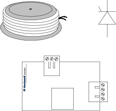
Silicon-Controlled Rectifiers (SCRs)
Each drive uses silicon-controlled rectifiers (SCRs) in the thyristor bridge to switch the incoming 3-phase AC power to DC output power.
These SCRs allow current to flow from anode to cathode when two conditions are met. First, like a diode, it must be forward biased. Second, an appropriate pulse must be applied to the gate (through the pulse transformer board).
The current will continue through the SCR until the voltage across it reverses and the current drops to zero (called line commutation). Figure 1.11 shows a picture of an SCR, depicting its polarity.
Publication 2361-5.01 July 1998
1-16 |
Product Overview |
Snubbers
Snubbers (resistor/capacitor assemblies) are installed in parallel with the SCRs, working with the cell reactors to provide adequate voltage suppression when the SCRs switch off.
Armature-Pulse Transformer Boards
Armature-pulse transformer boards provide the appropriate gate voltage and current to trigger an SCR. In addition, these boards provide gate driver isolation from the control logic. Figure 1.11 shows an armature-pulse transformer board.
DC Contactor
The main DC contactor is used to break the DC current to the motor armature. Coil voltage to the contactor is controlled by contacts from the pilot relay.
Figure 1.11
Armature Bridge Hardware
S ilicon -Controlled Rectifier (SCR )
A n ode
G ate |
A n ode |
|
G ate
Leads
Cath od e
C ath od e
A rm ature -Pulse Transform er B oard
J2 |
J1
Publication 2361-5.01 July 1998
 Loading...