


Stepper Controller
Module
(Catalog No. 1746-HSTP1)
User Manual

Important User Information Because of the variety of uses for the products described in this publication, those responsible for the application and use of this
control equipment must satisfy themselves that all necessary steps have been taken to assure that each application and use meets all performance and safety requirements, including any applicable laws, regulations, codes and standards.
The illustrations, charts, sample programs and layout examples shown in this guide are intended solely for purposes of example. Since there are many variables and requirements associated with any particular installation, Allen-Bradley does not assume responsibility or liability (to include intellectual property liability) for actual use based upon the examples shown in this publication.
Allen-Bradley publication SGI-1.1, Safety Guidelines for the Application, Installation and Maintenance of Solid-State Control
(available from your local Allen-Bradley office), describes some important differences between solid-state equipment and electromechanical devices that should be taken into consideration when applying products such as those described in this publication.
Reproduction of the contents of this copyrighted publication, in whole or part, without written permission of Rockwell Automation, is prohibited.
Throughout this manual we use notes to make you aware of safety considerations:
ATTENTION |
Identifies information about practices or |
|
circumstances that can lead to personal injury or |
||
! |
||
death, property damage or economic loss |
Attention statements help you to:
•identify a hazard
•avoid a hazard
•recognize the consequences
IMPORTANT |
Identifies information that is critical for successful |
|
application and understanding of the product. |
||
|
||
|
||
|
|
Allen-Bradley is a trademark of Rockwell Automation
European Communities (EC)
Directive Compliance
If this product has the CE mark it is approved for installation within the European Union and EEA regions. It has been designed and tested to meet the following directives.
EMC Directive
This product is tested to meet the Council Directive 89/336/EC Electromagnetic Compatibility (EMC) by applying the following standards, in whole or in part, documented in a technical construction file:
•EN 50081-2 EMC — Generic Emission Standard, Part 2 — Industrial Environment
•EN 50082-2 EMC — Generic Immunity Standard, Part 2 — Industrial Environment
This product is intended for use in an industrial environment.
Low Voltage Directive
This product is tested to meet Council Directive 73/23/EEC Low Voltage, by applying the safety requirements of EN 61131-2 Programmable Controllers, Part 2 - Equipment Requirements and Tests. For specific information required by EN 61131-2, see the appropriate sections in this publication, as well as the Allen-Bradley publication Industrial Automation Wiring and Grounding Guidelines For Noise Immunity, publication 1770-4.1.
This equipment is classified as open equipment and must be mounted in an enclosure during operation to provide safety protection.

Table of Contents
Table of Contents
Preface |
Using This Manual |
|
|
Overview . . . . . . . . . . . . . . . . . . . . . . . . . . . . . . . . . . . . . |
P-1 |
|
Contents of this Manual. . . . . . . . . . . . . . . . . . . . . . . . . . . |
P-1 |
|
Intended Audience . . . . . . . . . . . . . . . . . . . . . . . . . . . . . . |
P-2 |
|
Conventions . . . . . . . . . . . . . . . . . . . . . . . . . . . . . . . . . . . |
P-2 |
|
Rockwell Automation Support . . . . . . . . . . . . . . . . . . . . . . |
P-2 |
|
Local Product Support . . . . . . . . . . . . . . . . . . . . . . . . . |
P-3 |
|
Technical Product Assistance . . . . . . . . . . . . . . . . . . . . |
P-3 |
|
On the Web . . . . . . . . . . . . . . . . . . . . . . . . . . . . . . . . . . . |
P-3 |
Chapter 1 |
Module Overview |
|
|
Chapter Objectives . . . . . . . . . . . . . . . . . . . . . . . . . . . . . . |
1-1 |
|
Stepper Controller . . . . . . . . . . . . . . . . . . . . . . . . . . . . . . . |
1-1 |
|
Operating Modes . . . . . . . . . . . . . . . . . . . . . . . . . . . . . . . |
1-2 |
|
Configuration Mode . . . . . . . . . . . . . . . . . . . . . . . . . . . . . |
1-2 |
|
Command Mode Operation . . . . . . . . . . . . . . . . . . . . . . . . |
1-3 |
|
Diagnostic Mode . . . . . . . . . . . . . . . . . . . . . . . . . . . . . . . . |
1-3 |
|
LED Indicator Diagnostics . . . . . . . . . . . . . . . . . . . . . . . . . |
1-4 |
|
Input/Output Terminals. . . . . . . . . . . . . . . . . . . . . . . . . . . |
1-5 |
|
Terminal Block Release Screws . . . . . . . . . . . . . . . . . . . . . |
1-5 |
Chapter 2 |
Installation and Wiring |
|
|
Chapter Objectives . . . . . . . . . . . . . . . . . . . . . . . . . . . . . . |
2-1 |
|
General Precautions . . . . . . . . . . . . . . . . . . . . . . . . . . . . . |
2-1 |
|
Installation . . . . . . . . . . . . . . . . . . . . . . . . . . . . . . . . . . . . |
2-1 |
|
Wiring . . . . . . . . . . . . . . . . . . . . . . . . . . . . . . . . . . . . . . . |
2-2 |
|
Starting and Stopping the Module . . . . . . . . . . . . . . . . . . . |
2-2 |
|
Wiring for a Differential Interface. . . . . . . . . . . . . . . . . . . . |
2-2 |
|
Wiring to Optocoupler Interface . . . . . . . . . . . . . . . . . . . . |
2-3 |
|
Wiring to Optocoupler Interface (Continued) . . . . . . . . . . . |
2-5 |
|
Wiring Information for TTL Interface . . . . . . . . . . . . . . . . . |
2-5 |
|
Typical Input Circuitry. . . . . . . . . . . . . . . . . . . . . . . . . . . . |
2-6 |
|
Typical Encoder Timing Diagram. . . . . . . . . . . . . . . . . . . . |
2-7 |
|
Encoder Feedback Connections . . . . . . . . . . . . . . . . . . . . . |
2-8 |
i |
Publication 999-121 - December 1999 |

Table of Contents ii
Chapter 3 Start Up and Troubleshooting
Chapter Objectives . . . . . . . . . . . . . . . . . . . . . . . . . . . . . . 3-1
System Start Up. . . . . . . . . . . . . . . . . . . . . . . . . . . . . . . . . 3-1
Normal Operation . . . . . . . . . . . . . . . . . . . . . . . . . . . . . . . 3-1
Troubleshooting . . . . . . . . . . . . . . . . . . . . . . . . . . . . . . . . 3-1
Safety Precautions . . . . . . . . . . . . . . . . . . . . . . . . . . . . . . . 3-3
Removing the Module . . . . . . . . . . . . . . . . . . . . . . . . . . . . 3-3
Chapter 4 |
Module Operation |
|
|
Chapter Objectives . . . . . . . . . . . . . . . . . . . . . . . . . . . . . . |
4-1 |
|
Module Overview . . . . . . . . . . . . . . . . . . . . . . . . . . . . . . . |
4-1 |
|
Operating Modes . . . . . . . . . . . . . . . . . . . . . . . . . . . . . . . |
4-1 |
|
Configuration. . . . . . . . . . . . . . . . . . . . . . . . . . . . . . . . |
4-1 |
|
Command . . . . . . . . . . . . . . . . . . . . . . . . . . . . . . . . . . |
4-2 |
|
Operation Using the Pulse and Direction Outputs . . . . . |
4-2 |
|
Fixed Speed Operation . . . . . . . . . . . . . . . . . . . . . . . . |
4-2 |
|
Origin (Home) Search Sequence of Operation. . . . . . . . |
4-3 |
|
Resetting the Current Absolute Position. . . . . . . . . . . . . |
4-3 |
Chapter 5 |
Configuration and Programming |
|
|
Chapter Objectives . . . . . . . . . . . . . . . . . . . . . . . . . . . . . . |
5-1 |
|
Programming Conventions . . . . . . . . . . . . . . . . . . . . . . . . |
5-1 |
|
Configuration and Status Bits . . . . . . . . . . . . . . . . . . . . . . . |
5-1 |
|
Program Scan . . . . . . . . . . . . . . . . . . . . . . . . . . . . . . . . . . |
5-1 |
|
SLC Processor Configuration . . . . . . . . . . . . . . . . . . . . . . . |
5-1 |
|
Processor configuration using APS . . . . . . . . . . . . . . . . |
5-2 |
|
Processor configuration using HHT (Catalog 1747–PT1). 5-2 |
|
|
Module Configuration . . . . . . . . . . . . . . . . . . . . . . . . . . . . |
5-3 |
|
General Information. . . . . . . . . . . . . . . . . . . . . . . . . . . |
5-3 |
|
Configuration Error . . . . . . . . . . . . . . . . . . . . . . . . . . . |
5-3 |
|
Configuration mode output image table . . . . . . . . . . . . |
5-3 |
|
Configuration mode input image table . . . . . . . . . . . . . |
5-6 |
|
Invalid Configurations . . . . . . . . . . . . . . . . . . . . . . . . . |
5-6 |
|
Programming Command Mode . . . . . . . . . . . . . . . . . . . . . |
5-8 |
|
Output Words – SLC Processor to Stepper Controller. . . |
5-8 |
|
Output Command Word 0 Bit Definition . . . . . . . . . . . . . . . . . . |
. 5-8 |
|
Command Mode Output Words. . . . . . . . . . . . . . . . . . . . . . . . . . |
. 5-8 |
|
Output Command Bits for Word 0 . . . . . . . . . . . . . . . . |
5-10 |
|
Absolute/relative move commands . . . . . . . . . . . . . . . . |
5-11 |
|
Homing Routines . . . . . . . . . . . . . . . . . . . . . . . . . . . . . . . |
5-14 |
|
Home to Limit Switch. . . . . . . . . . . . . . . . . . . . . . . . . . |
5-14 |
|
Home to Proximity Limit Switch and Home Limit Switch 5-14 |
|
Publication 999-121 - December 1999
Table of Contents |
iii |
|
|
Home to Proximity Limit Switch and Marker . . . . . . . . . 5-14
Programming Simple Moves . . . . . . . . . . . . . . . . . . . . . . . 5-16
General Information. . . . . . . . . . . . . . . . . . . . . . . . . . . 5-16
Data File Structures . . . . . . . . . . . . . . . . . . . . . . . . . . . 5-16
Using the N Files for Motion Commands . . . . . . . . . . . . 5-17
Quadrature Encoder Input . . . . . . . . . . . . . . . . . . . . . . 5-17
Use of Direct Inputs. . . . . . . . . . . . . . . . . . . . . . . . . . . 5-17
Programming Blended Moves . . . . . . . . . . . . . . . . . . . . . . 5-18
General Information. . . . . . . . . . . . . . . . . . . . . . . . . . . 5-18
Blend move programming routine . . . . . . . . . . . . . . . . 5-19
Module Status Inputs. . . . . . . . . . . . . . . . . . . . . . . . . . . . . 5-22
Input Word 0. . . . . . . . . . . . . . . . . . . . . . . . . . . . . . . . 5-22
Input Word 1. . . . . . . . . . . . . . . . . . . . . . . . . . . . . . . . 5-24
Input Words 2 and 3 . . . . . . . . . . . . . . . . . . . . . . . . . . 5-25
Input Words 4 and 5 . . . . . . . . . . . . . . . . . . . . . . . . . . 5-25
Diagnostics Feedback Test. . . . . . . . . . . . . . . . . . . . . . . . . 5-25
Configuration Data for Loop Back Diagnostic Test. . . . . 5-26
Ladder Instructions for Loop Back Diagnostics Test . . . . 5-26
Command Mode Input Words . . . . . . . . . . . . . . . . . . . . . . . . . . . 5-28
Chapter 6 |
Application Examples |
|
|
Chapter Objectives . . . . . . . . . . . . . . . . . . . . . . . . . . . . . . |
6-1 |
|
Data table used for the program listing for |
|
|
Sample Module Check Procedure . . . . . . . . . . . . . . . . . |
6-1 |
|
Program Listing for Sample Module Check Procedure . . |
6-1 |
|
Entering Negative Position Data . . . . . . . . . . . . . . . . . . |
6-4 |
|
Converter Example . . . . . . . . . . . . . . . . . . . . . . . . . . . |
6-5 |
Appendix A |
Specifications |
|
|
Industry Standards . . . . . . . . . . . . . . . . . . . . . . . . . . . . . . |
A-1 |
|
General Specifications . . . . . . . . . . . . . . . . . . . . . . . . . . . . |
A-1 |
|
LED Indicators . . . . . . . . . . . . . . . . . . . . . . . . . . . . . . . |
A-1 |
|
Power Requirements . . . . . . . . . . . . . . . . . . . . . . . . . . |
A-2 |
|
System Limitations . . . . . . . . . . . . . . . . . . . . . . . . . . . . |
A-2 |
|
Discrete Inputs . . . . . . . . . . . . . . . . . . . . . . . . . . . . . . |
A-2 |
|
Discrete Outputs . . . . . . . . . . . . . . . . . . . . . . . . . . . . . |
A-2 |
|
Input/Output Terminals . . . . . . . . . . . . . . . . . . . . . . . . |
A-3 |
|
Environmental Operating Conditions . . . . . . . . . . . . . . |
A-3 |
|
Storage Temperature . . . . . . . . . . . . . . . . . . . . . . . . . . |
A-3 |
|
Feedback Circuitry . . . . . . . . . . . . . . . . . . . . . . . . . . . . |
A-3 |
|
Program Storage Requirements . . . . . . . . . . . . . . . . . . . |
A-3 |
|
Processor Compatibility . . . . . . . . . . . . . . . . . . . . . . . . |
A-3 |
Publication 999-121 - December 1999

Table of Contents iv
Appendix B Input/Output Quick Reference
Index
Publication 999-121 - December 1999

Preface
Overview
Contents of this Manual
Using This Manual
Read this chapter to familiarize yourself with the rest of the manual. It provides information concerning the:
•contents of this manual
•intended audience
•conventions used
•hazards of injury or equipment damage
This manual provides specific information relevant to the Stepper Controller Module, Catalog Number 1746–HSTP1. The following table identifies the chapters, titles and contents.
Chapter |
Title |
Contents |
|
|
|
Preface |
Using This Manual |
An overview of this manual |
|
|
|
1 |
Module Overview |
Module Overview, its operation and |
|
|
hardware features |
|
|
|
2 |
Installation and |
Interconnection diagrams for various |
|
Wiring |
hardware interfaces for communication |
|
|
with the Stepper Controller. |
|
|
|
3 |
Start Up and |
Start up, normal states of LED indicators, |
|
Troubleshooting |
troubleshooting and error handling |
|
|
information. |
|
|
|
4 |
Module Operation |
Describes interface selection, the Module’s |
|
|
use of inputs and outputs, and operating |
|
|
modes |
|
|
|
5 |
Configuration and |
Provides the steps necessary to configure |
|
Programming/Status |
the SLC™ Processor and Stepper Controller |
|
|
|
6 |
Application Examples |
Illustrated sequencer, configuration and |
|
|
command data files. |
|
|
|
Appendix A |
Specifications |
Temperature, humidity, input output, |
|
|
voltage, timing and cabling information. |
|
|
|
Appendix B |
Input/Output Quick |
A quick reference for the Input/Output |
|
Reference |
config and command bits and words. |
|
|
|
1 |
Publication 999-121 - December 1999 |

P-2 Using This Manual
Intended Audience
Conventions
Rockwell Automation
Support
This manual is designed for the qualified first time user who has a working knowledge of SLC 500™ products. If necessary, obtain the proper training before using the Stepper Controller.
The following terms are used throughout this manual:
Input file – refers to the Module's Input Data file. This file is updated during the SLC Processor input scan
Output file – refers to the Module's Output Data file. This file is updated during the SLC Processor output scan.
Module – refers to the Stepper Controller, catalog number 1746-HSTP1
Physical outputs – refers to actual outputs on the Stepper Controller
SLC Processor – refers to an SLC 500 family processor
Stepper Translator – refers to the interface between the Stepper Controller and the stepper motor that converts pulse train outputs into power signals used to run the motor.
Position Loop – refers to the ability of a controller to accurately position a mechanism to a precise point based on a dynamic comparison of command data and feedback from a sensor.
Engineering Units – refer to decimal fractions of units of measurement; e.g., inches, millimeters and degrees.
CW – refers to rotation or movement in a clockwise direction.
CCW – refers to rotation or movement in a counter-clockwise direction.
Rockwell Automation offers support services worldwide, with over 75 sales/support offices, 512 authorized distributors, and 260 authorized systems integrators located throughout the United States. In addition, Rockwell Automation representatives are located in every major country in the world.
Publication 999-121 - December 1999
Using This Manual |
P-3 |
|
|
Local Product Support
Contact your local Rockwell Automation representative for:
•sales and order support
•product technical training
•warranty support
•support service agreements
Technical Product Assistance
On the Web
If you need to contact Rockwell Automation for technical assistance, please review the information in this manual. If the problem persists, call your local Rockwell Automation representative.
The Rockwell Automation Technical Support number is:
1-603-443-5419
For information about Allen-Bradley, visit the following World Wide Web site:
http://www.ab.com/
Publication 999-121 - December 1999
P-4 Using This Manual
Publication 999-121 - December 1999

Chapter 1
Chapter Objectives
Stepper Controller
Module Overview
The Module overview will permit you to understand the basic functions of the Module and hardware requirements.
The Module, catalog number 1746–HSTP1, is an SLC 500 family compatible device. It can be used with any SLC 500 Processor.
The Module is configured through the SLC 500 backplane and requires no switch settings. Motion can be programmed in either direction for over ±8,000,000 counts of absolute position.
An optional incremental encoder may be used to verify the position reached by the axis. The Module does not automatically close a position loop in engineering units. The feedback hardware can accept frequencies of up to 250 kHz for use as either loop back diagnostics or differential incremental encoder feedback devices.
The Module can be programmed for either incremental or absolute moves, depending on the application.
The Module supports two differential outputs, to suit the type of Stepper Translator used, which provide the following control commands:
•CW or non-directional pulse output
•CCW or direction signal output
Discrete inputs are provided for:
•External Interrupt
•Home Limit Switch
•Home Proximity Input
•CW Travel Limit Switch Input
•CCW Travel Limit Switch Input
•Pulse Train Enable/Disable Input
1 |
Publication 999-121 - December 1999 |
1-2 Module Overview
Operating Modes
Configuration Mode
Differential inputs are provided for:
•Encoder Channel A and A NOT
•Encoder Channel B and B NOT
•Encoder Marker Channel
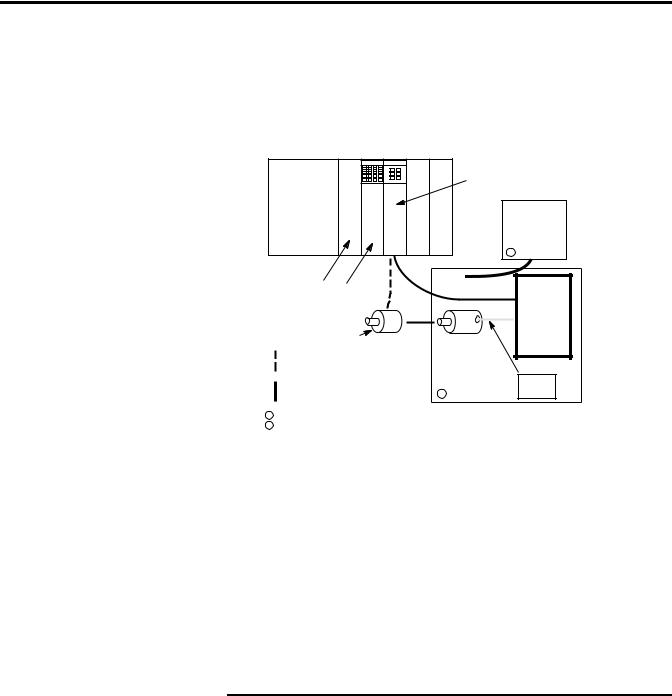
Figure 1.1 Stepper Module Overview
Stepper
Controller
SLC
Power
Supply 7 to 24V DC
User Power
Supply
|
|
1 |
SLC |
|
|
Processor Standard |
|
|
I/O Module |
|
Stepper |
|
|
|
|
|
Translator |
Optional |
Stepper |
|
Encoder |
|
|
Motor |
|
|
Optional Feedback Wiring |
|
|
|
|
|
Control Wiring to Translator |
|
Power |
2 |
Wires |
1 The 24V may be obtained from the SLC Power Supply depending on application power requirements. 2 Motor and translator furnished by the customer.
The Module operates in three different modes: configuration, command, and diagnostic. The three operating modes are summarized below.
The configuration mode is commanded by setting the mode flag (bit 15 in output word 0) to 1. In this mode, the Module is configured through the SLC Processor to perform specific operations that the user desires. The configuration mode defines the basic operation of the Module.
|
The Module does not operate until it has been |
|
IMPORTANT |
||
configured at least once. |
||
|
||
|
||
|
|
Publication 999-121 - December 1999
Module Overview |
1-3 |
|
|
Command Mode Operation
Diagnostic Mode
The Module can be configured to:
•Determine which inputs are used.
•Determine the active level of inputs used.
•Set whether just the encoder marker or a prox limit switch and encoder marker combination is used for homing.
•Determine if a quadrature encoder will be used.
•Select whether the Module output is a pulse train with direction command or a CW pulse train and CCW pulse train.
•Select between configuration mode and command mode.
NOTE: Some output combinations are not valid. For example, using feedback diagnostics and quadrature encoder or using a marker pulse and a home limit switch. If any invalid combinations are sent, the configuration error input bit will be set.
All stepper motor operations are performed in command mode. This mode is entered by setting the mode flag (bit 15 in output word 0) to 0.
In command mode, the SLC Processor can issue commands and activate different operations or moves. The actions you can command are:
•Absolute Moves
•Relative Moves
•Hold Moves
•Resume Moves
•Immediate Stop Operations
•Homing Operations
•Jogging Operations
•Blend Moves
•Preset Operations
•Reset Errors
Use the configuration mode to select the diagnostic mode of operation. Once selected, the diagnostic mode allows you to test your program and wiring by connecting the loop back wires at the translator. The purpose of loop back diagnostics is to test the system wiring for electrical noise. The number of pulses received at the feedback should equal the commanded number of pulses at the end of the move. If they are not equal, the system may be experiencing problems due to electrical noise.
Publication 999-121 - December 1999

1-4 Module Overview
LED Indicator Diagnostics |
There are five diagnostic LED indicators provided as shown below. |
|||||||||
|
|
|
|
Their purpose is to aid in identifying operational problems. |
||||||
|
|
|
|
Figure 1.2 LED Indicators |
|
|
|
|||
|
|
|
|
|
|
|
|
|
|
|
|
Processor and System O.K. |
|
|
|
|
|
|
|
||
|
|
|
|
|
|
|
|
|||
|
|
|
|
|
|
|
|
|
|
|
|
Commanding a |
|
|
|
STEPPER |
|
Controller Commanding |
|||
|
Counterclockwise Move |
|
|
|
|
RUN |
|
Clockwise Motion |
||
|
|
|
|
|
|
|||||
|
An error occurred during |
|
|
|
|
No configuration file present |
||||
|
|
|
|
|
|
|||||
|
command mode operations |
|
|
CCW |
|
or invalid configuration |
||||
|
|
|
|
|
|
CW |
||||
|
|
|
|
|
|
ERR |
FLT |
|||
|
|
|
|
|
|
|
|
|
|
|
|
|
|
|
|
|
|
|
|
|
RUN |
|
|
|
|
|
|
|
|
|
|
|
|
|
|
|
|
||
|
|
|
|
|
|
|
|
||
|
CCW |
|
|
|
CW |
|
|||
|
|
|
|
|
|
|
|
||
|
ERR |
|
|
|
FLT |
|
|||
|
|
|
|
|
|
|
|
|
|
|
|
|
|
|
|
|
|
|
|
|
|
|
|
|
|
|
|
|
|
|
|
|
|
|
|
|
|
|
|
|
|
|
|
|
|
|
|
|
|
|
|
|
|
|
|
|
|
|
|
|
|
|
|
|
|
|
|
|
|
|
|
|
|
|
|
|
|
|
|
|
|
|
|
|
|
|
|
|
|
|
|
|
|
|
|
|
|
|
|
|
|
|
|
|
|
|
|
|
|
|
|
|
|
|
|
|
|
|
|
|
|
|
|
|
|
|
|
|
|
|
|
|
|
|
|
|
|
|
|
|
|
|
|
|
|
|
|
|
|
|
|
|
|
|
|
|
|
|
|
|
|
|
|
|
|
|
|
|
|
|
|
|
|
|
|
|
|
|
|
|
|
|
|
|
|
|
|
|
|
|
|
|
|
|
|
|
|
|
|
|
|
|
|
|
|
|
|
|
|
|
|
|
|
|
|
|
|
|
|
|
|
|
|
|
|
|
|
|
|
|
|
|
|
|
|
|
|
|
|
|
|
|
|
|
|
|
|
|
|
|
|
|
|
|
|
|
|
|
|
|
|
|
|
|
|
|
|
|
|
|
|
|
|
|
|
|
|
|
|
|
|
|
|
|
|
|
|
|
|
|
|
|
|
|
|
|
|
|
|
|
|
|
|
|
|
|
|
|
|
|
|
|
|
|
|
|
|
|
|
|
|
|
|
|
|
|
|
|
|
|
|
|
|
|
|
|
|
|
|
|
|
|
|
|
|
|
|
|
|
Publication 999-121 - December 1999
Module Overview |
1-5 |
|
|
Input/Output Terminals
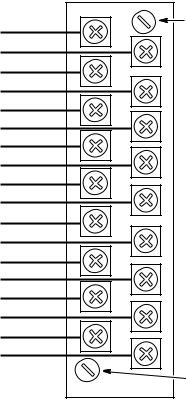
These terminals supply power and inputs to the Module and outputs to attached devices. Each can accommodate two #14 gauge wires.
Figure 1.3 Input/Output Terminals
7-24V DC user power |
(1) |
Release Screw |
(CCW loosen) |
||
CW + or non directional pulse output |
(2) |
|
CW - or non directional pulse output |
(3) |
|
CCW + pulse or direction signal output |
(4) |
|
CCW - pulse or direction signal output |
(5) |
|
External interrupt input |
(6) |
|
Home limit switch input |
(7) |
|
Home Proximity limit switch input |
(8) |
|
CW limit switch input |
(9) |
|
CCW limit switch input |
(10) |
|
Pulse train enable/disable input |
(11) |
|
A Hi (Loopback + non directional pulse) |
(12) |
|
A Lo (Loopback - non directional pulse) |
(13) |
|
B Hi (Loopback + direction) |
(14) |
|
B Lo (Loopback - direction |
(15) |
|
+ Encoder Marker |
(16) |
|
- Encoder Marker |
(17) |
|
0 V user power (DC common) |
(18) |
|
Release Screw (CCW loosen)
Terminal Block Release
Screws
These captive screws are attached to the terminal block. As the screws are loosened, the terminal block moves away from the Module. This feature facilitates replacement of the Module without rewiring.
Publication 999-121 - December 1999

1-6 Module Overview
Publication 999-121 - December 1999
Chapter 2
Chapter Objectives
General Precautions
Installation
Installation and Wiring
This chapter provides information which permits you to properly unpack, install and wire the interfaces between the Module and the various Stepper Translators that can be used with the Module. Also covered are typical input circuitry (direct input and encoder input), and encoder timing information and encoder feedback connections.
In addition to the precautions listed throughout this manual, the following statements which are general to the system must be read and understood.
ATTENTION
!
This drive contains ESD (Electrostatic Discharge) sensitive parts and assemblies. Static control precautions are required when installing, testing, servicing or repairing this assembly. Component damage may result if ESD static control procedures are not followed. If you are not familiar with static control procedures, reference A–B publication 8000– 4.5.2, “Guarding Against Electrostatic Damage” or any other applicable ESD protection handbook.
An incorrectly applied or installed Module can result in component damage or a reduction in product life. Wiring or application errors, such as, undersizing the motor, incorrect or inadequate AC supply, or excessive ambient temperatures may result in malfunction of the system.
Only personnel familiar with the Module and associated machinery should plan or implement the installation, start-up and subsequent maintenance of the system. Failure to comply may result in personal injury and/or equipment damage.
1.Install the Module in the designated slot in your SLC controller rack. Refer to your SLC controller user manual.
2.Wire the input and output devices as instructed in the following information.
1 |
Publication 999-121 - December 1999 |
2-2 Installation and Wiring
Wiring
Refer to the following information on typical interface requirements before beginning this procedure.
ATTENTION
!
The following information is merely a guide for proper installation. The Allen-Bradley Company cannot assume responsibility for the compliance or the noncompliance to any code, national, local or otherwise for the proper installation of this drive or associated equipment. A hazard of personal injury and/or equipment damage exists if codes are ignored during installation.
To meet the installation requirements of Underwriters Laboratories Inc. standard UL 508 for industrial control equipment, follow the guidelines below.
•Use 60/75° C copper wire when wiring the 1746–HSTP1 system.
•Tighten the terminals on the 1746-HSTP1 to 5 lb/in.
•Use Class 1 or Class 2 wiring for the terminals on the 1746– HSTP1 system.
For more information, refer to standard UL 508 or the National Electric Code.
Starting and Stopping the
Module
ATTENTION
!
The Module Enable/Disable control circuitry includes solid-state components. If hazards due to accidental contact with moving machinery or unintentional flow of liquid, gas or solids exist, an additional hardwired stop circuit is required.
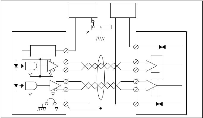
Wiring for a Differential Interface
Several manufacturers of Stepper Translators provide differential inputs. If your Stepper Translator can accept differential line driver outputs, follow the interconnection diagram below to connect the Stepper Controller to the translator.
Publication 999-121 - December 1999
Installation and Wiring |
2-3 |
|
|
Typical Input Connection
(Refer to page 6-6)
Stepper Controller
Voltage
Regulator
Figure 2.1 Differential Input
|
7-24V DC |
|
User |
|
|
Power Supply |
|
|
|
|
|
(+) |
(-) |
(-) |
(+) |
|
16 AWG |
|
|
|
16 AWG |
|
|
|
Electrical Cabinet |
|
|
1 |
Ground Bus |
|
|
|
|
|
|
2 |
|
|
|
3 |
|
|
|
4 |
|
|
|
5 |
|
|
|
18 |
|
|
|
Driver |
|
External |
Internal |
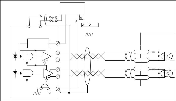
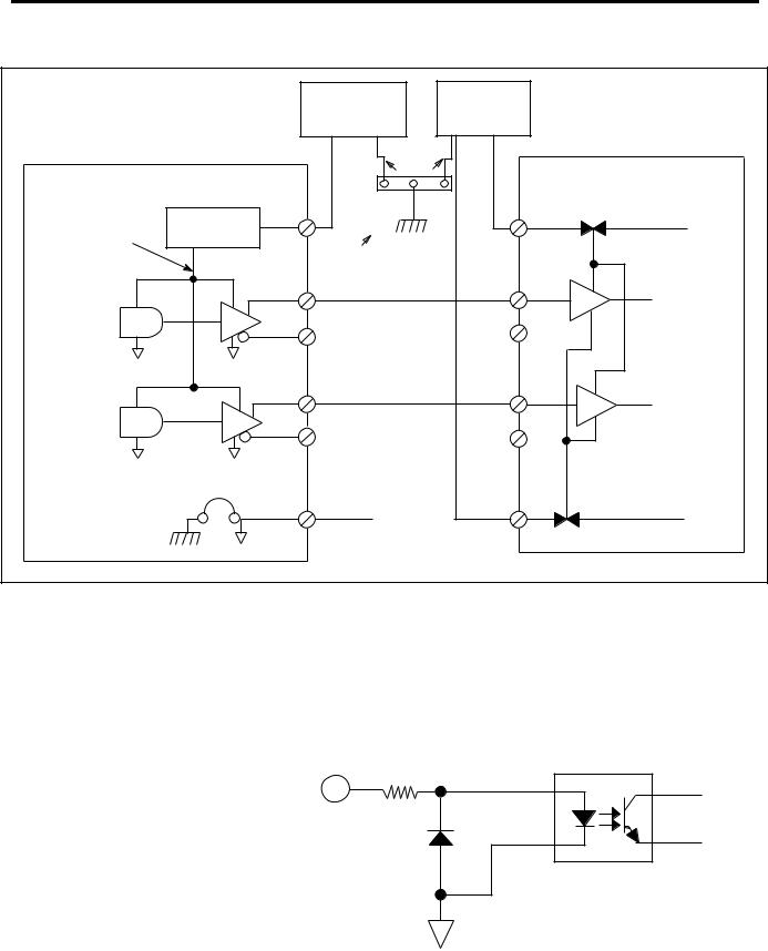
Wiring to Optocoupler Interface
The following diagrams show the circuitry used to interface the Module to a Stepper Translator through two different optocoupler devices. The first diagram shows an optocoupler designed for a common power supply connection. The second diagram shows an individually isolated optocoupler. It is your responsibility to determine which type is used in your specific application, and to ensure that connections are properly made.
Publication 999-121 - December 1999
2-4 |
Installation and Wiring |
|
|
|
|
|
|
Figure 2.2 Optocoupler Input Common Supply |
|||
|
Typical Input Connection |
|
7-24V DC |
|
5V DC |
|
|
|
|
||
|
(Refer to page 6-6) |
|
|
|
|
|
|
(+) |
(-) |
(+) |
(-) |
|
|
|
|
16 AWG |
|
|
Stepper Controller |
|
16 AWG |
|
Driver |
|
|
|
|
||
|
Voltage |
1 |
|
Electrical Cabinet |
|
|
|
Ground Bus |
|
||
|
Regulator |
|
|
|
|
|
|
|
|
|
|
|
|
2 |
|
|
|
|
|
3 |
|
|
|
|
|
4 |
|
|
|
|
|
5 |
|
|
|
|
|
18 |
|
|
|
Publication 999-121 - December 1999
Installation and Wiring |
2-5 |
|
|
Wiring to Optocoupler |
Figure 2.3 Individually Isolated Optocoupler |
Interface (Continued) |
|
|
|
|
7-24V DC |
|
Typical Input |
(+) |
(-) |
||
Connection |
||||
|
|
|||
|
|
|
16 AWG |
|
|
|
|
16 AWG |
|
10 |
9 |
|
|
|
CCW Limit |
CW Limit |
|
|
|
Stepper Controller |
|
|
Typical Driver |
|
|
|
1 |
Electrical Cabinet |
|
|
Voltage |
Ground Bus |
||
|
Regulator |
|
|
|
|
|
2 |
220 W |
|
|
|
+PLS |
||
|
|
3 |
Pulse Input |
|
|
|
-PLS |
||
|
|
|
||
|
|
|
-20mA Max. |
|
|
|
4 |
220 W |
|
|
|
+CW/CCW |
||
|
|
5 |
Direction Input |
|
|
|
-CW/CCW |
||
|
|
|
||
|
|
|
-20mA Max. |
|
|
|
18 |
|
|
Wiring Information for TTL Interface
The following wiring diagram shows the connections between the Module and a Stepper Translator that requires a TTL Interface. The 5-volt supply to the TTL interface can be either internal to the translator itself or a separate power supply selected by the user. This design is probably the most sensitive to noise due to the single ended, high-speed nature of the TTL device. For this reason, it should be used only where the Stepper Translator is close to the Module, that is, no more than five cable feet, in an enclosure that is well shielded from EMI noise when the enclosure doors are closed.
Publication 999-121 - December 1999
2-6 Installation and Wiring
Figure 2.4 TTL Interface
Typical Input Connection |
|
7-24V DC |
|
|
5V |
|
|
|
|
|
|
|
|
(Refer to page 6-6) |
|
|
|
(-) |
(+) |
|
|
|
(+) |
(-) |
|
||
|
|
|
16 AWG |
|
Driver |
|
Stepper Controller |
|
|
|
|
|
|
|
|
|
|
|
|
|
|
Voltage |
1 |
|
|
External |
Internal |
|
|
|
|
|
|
|
5V DC |
Regulator |
16 AWG |
Electrical Cabinet |
|
|
|
|
|
|
|
|||
|
|
|
|
|
||
|
|
|
Ground Bus |
|
|
|
|
|
2 |
|
|
|
|
|
|
3 |
|
|
|
|
|
|
4 |
|
|
|
|
|
|
5 |
|
|
|
|
|
|
18 |
|
|
|
|
Typical Input Circuitry
Two basic circuits are used for inputs to the Module. One type is the direct input circuit for home limit switches, overtravel limits, and interrupt devices. The second type is for encoder inputs. Both circuits are shown below.
Figure 2.5 Direct input equivalent circuit
2.2K
Publication 999-121 - December 1999
Installation and Wiring |
2-7 |
|
|
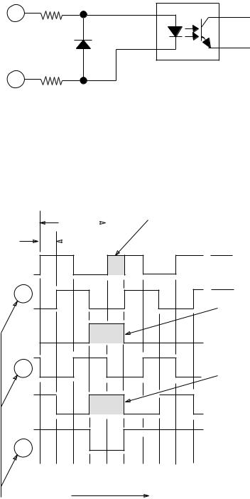
Figure 2.6 Encoder input equivalent circuit
HI
210
LO
210
Typical Encoder Timing
Diagram
A typical encoder timing diagram is shown below. For actual connections, consult your encoder manufacturer's timing diagram. For all encoder types, if the direction (phasing) of the feedback is backwards, correct this condition by reversing the channel A and channel B connections.
|
1 Cycle |
|
|
STEP 3 |
|
|
|
|
Channel A is high at least part |
||
|
|
|
|
|
|
|
|
|
|
|
of marker interval. Connect to |
90’ |
|
|
|
|
CH A. HI" of termination point |
|
|
|
|
||
|
|
|
|
|
|
Hi
Channel A
B
Z |
Optional
A
B
Lo
STEP 1
High marker interval. Connect to + encoder marker.
STEP 2
B is high for at least part of marker interval. Connect to CH B. HI"
Z
CCW rotation viewing shaft
Wire CH B, CH A, and CH Z to CH B LO, CH A LO, and CH Z LO, respectively on the terminal block.
Publication 999-121 - December 1999
2-8 Installation and Wiring
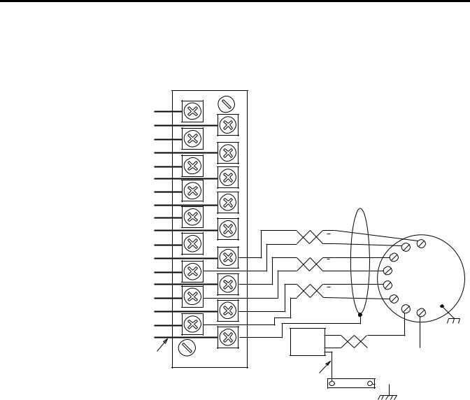
Encoder Feedback
Connections
The following two diagrams illustrate encoder connections to the Module inputs for both 5-volt and 15-volt encoder power supplies. The -notes" included with each diagram provide specifics on wiring.
Figure 2.7 5-volt encoder feedback connections
7-24V DC user power |
(1) |
CW + or non directional pulse output |
(2) |
CW - or non directional pulse output |
(3) |
CW + pulse or direction signal output |
(4) |
CCW - pulse or direction signal output |
(5) |
External interrupt input |
(6) |
Home limit switch input |
(7) |
Home Proximity limit switch input |
(8) |
CW limit switch input |
(9) |
CCW limit switch input |
(10) |
Pulse train enable/disable input |
(11) |
A Hi (Loopback + non directional pulse) |
(12) |
A Lo (Loopback - non directional pulse) |
(13) |
B Hi (Loopback + direction) |
(14) |
B Lo (Loopback - direction |
(15) |
+ Encoder Marker |
(16) |
- Encoder Marker |
(17) |
0 V user power (DC common) |
(18) |
16 AWG
1A
|
A |
|
|
|
|
1 |
B |
|
H |
A |
|
|
|
|
|||
|
B |
B |
A-B 845H |
3 |
|
1 |
Z |
I |
|
||
C |
Optical |
|
|||
|
Z |
Encoder |
|
||
|
J |
|
|
|
|
|
|
D |
|
G |
|
|
|
|
F |
||
|
|
|
|
|
|
DC |
+5V |
|
|
Case Ground |
|
|
|
|
|
|
|
SOURCE |
|
|
|
|
|
|
Return |
|
|
|
|
16 AWG |
|
|
|
|
|
|
|
Electrical Cabinet |
|
|
|
|
|
Ground Bus |
|
|
|
Notes: |
1. |
Use 3-pair, #22 gauge individually twisted and shielded pair, |
|
|
Belden 9504 or equivalent. |
|
2. |
Use 1-pair, #18 gauge twisted and shielded cable. |
|
3. |
Encoders must have +5V compatible differential line drive |
|
|
outputs on channels A, B, and Z. (DS8830, or equivalent.) (A-B |
|
|
845H) |
|
4. |
+5V from encoder power source – connect encoder return to 0V |
|
|
user power (DC common) at the power supply sources. |
Publication 999-121 - December 1999
 Loading...