


Reference Manual
Bulletin 1606 Switched Mode Power Supplies
Catalog Number: 1606-XLSRED40
Index
|
|
Page |
|
|
|
Page |
1. |
Intended Use ....................................................... |
3 |
14. |
Certifications .................................................... |
12 |
|
2. |
Installation Requirements................................... |
3 |
15. |
Physical Dimensions and Weight ..................... |
13 |
|
3. |
Input and Output Characteristics ....................... |
4 |
16. |
Accessories ........................................................ |
14 |
|
4. |
Power Losses........................................................ |
5 |
17. |
Application Notes............................................. |
15 |
|
5. |
Lifetime Expectancy and MTBF........................... |
6 |
17.1. |
Recommendations for Redundancy......... |
15 |
|
6. |
Terminals and Wiring.......................................... |
7 |
17.2. Inductive and Capacitive Loads................ |
15 |
||
7. |
Functional Diagram............................................. |
8 |
17.3. |
Lateral Installation Clearances ............ |
15 |
|
8. |
Front Side and User Elements............................. |
8 |
17.4. 1+1 Redundancy up to 20A...................... |
16 |
||
9. |
EMC...................................................................... |
9 |
17.5. N+1 Redundancy, Example with 60A ...... |
16 |
||
10. |
Environment ...................................................... |
10 |
17.6. |
Mounting Orientations ............................ |
17 |
|
11. |
Protection Features ........................................... |
11 |
|
|
|
|
12. |
Safety Features.................................................. |
11 |
|
|
|
|
13. |
Dielectric Strength ............................................ |
11 |
|
|
|
|
Terminology and Abbreviations
•PE and  symbol—PE is the abbreviation for Protective Earth and has the same meaning as the symbol
  .
.
•Earth, Ground—This document uses the term “earth” which is the same as the U.S. term “ground”.
•T.b.d.—To be defined, value or description will follow later.
•DC 24V—A figure displayed with the AC or DC before the value represents a nominal voltage with standard tolerances (usually ±15%) included. E.g.: DC 12V describes a 12V battery whether it is full (13.7V) or flat (10V)
•24Vdc—A figure with the unit (Vdc) at the end is a momentary figure with no additional tolerance included.
•may, shall, should—Three key words indicating, respectively: flexibility of choice with no implied preference, a mandatory requirement, flexibility of choice
•1+1 Redundancy—Use of two identical power supplies in parallel to provide continued operation following most failures in a single power supply. The two power supply outputs should be isolated from each other by using diodes or other switching arrangements. E.g. two 10A power supplies are needed to achieve a 10A redundant system.
•N+1 Redundancy—Use of three or more identical power supplies in parallel to provide continued operation following most failures in a single power supply. All power supply outputs should be isolated from each other by using diodes or other switching arrangements. E.g. to achieve a 40A redundant system, five 10A power supplies are required in a N+1 redundant system.
|
|
N+1 |
|
|
|
|
|
Redundancy |
|
|
|
AC |
AC |
AC |
AC |
AC |
AC |
DC |
DC |
DC |
DC |
DC |
DC |
IN 1 |
IN 2 |
IN 1 |
IN 2 |
IN 1 |
IN 2 |
OUT |
OUT |
OUT |
|||
|
+ |
- |
|
|
|
|
Load |
|
|
|
|
1+1 |
|
Redundancy |
|
AC |
AC |
DC |
DC |
IN 1 |
IN 2 |
OUT |
|
+ |
- |
Load |
|
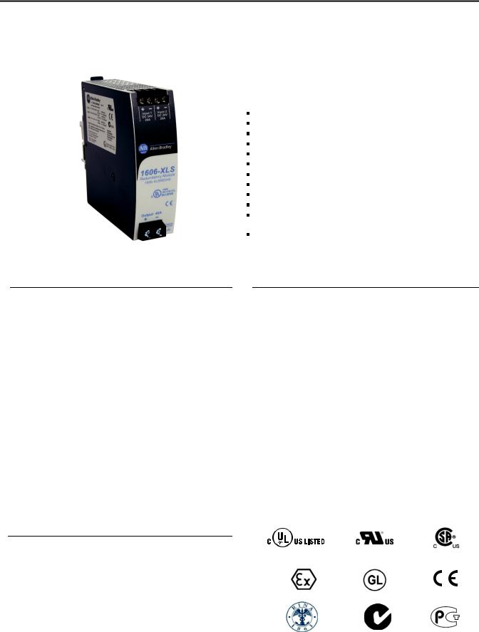
Bulletin 1606 Switched Mode Power Supplies
Mosfet Redundancy Module
For N+1 and 1+1 Redundant Systems Dual Input with Single Output Suitable for all Power Supplies
Only 72mV Voltage Drop at 20A Output Current
Only 2.15W Loss at 20A and 6.3W at 40A Output Current 160% (65A) Peak Load Capability
Reverse Input Polarity Protection Full Power Between -40°C and +70°C Width only 36mm
Rugged Metal Housing Easy Wiring:
Distribution Terminal for Negative Pole Included 3 Year Warranty
 Description
The 1606-XLSRED40 is a redundancy module which can be used to build 1+1 and N+1 redundant systems. It is equipped with two input channels, which can be connected to power supplies with up to 20A output current and one output, which can carry nominal currents up to 40A. The module is suitable for power supplies with constant current overload behavior as well as any kind of “Hiccup” overload behavior.
The novelty of this redundancy module is the utilization of mosfets instead of diodes for the decoupling of the two input channels. This reduces the heat generation and the voltage drop between input and output. The redundancy module does not require an additional auxiliary voltage and is self-sufficient even in case of a short circuit across the output.
Due to the low power losses, the unit is very slender and only requires 36mm width on the DIN rail. Large connection terminals allow for a safe and fast installation with a large international approval package. This unit is suitable for nearly every application.
 Catalog Numbers
Redundancy 1606-XLSRED40 12-28V Standard unit
Module
Accessory |
1606-XLC |
Wall/panel mount |
|
|
bracket |
 Specification Quick Reference
|
|
Input voltage |
|
DC 12-28V |
±30% |
|
|
|
Input voltage |
|
8.4-36.4Vdc |
|
|
|
|
range |
|
|
|
|
|
|
Input current |
|
2x 0-20A |
continuous |
|
|
|
|
|
2x 20-32.5A |
for 5 seconds |
|
|
|
Output current |
|
0-40A |
continuous |
|
|
|
|
|
40-65A |
for 5 seconds |
|
|
|
|
|
65A |
at cont. overload |
|
|
|
|
|
|
or short circuit |
|
|
|
Input to output |
typ. 72mV |
input: 2x10A |
|
|
|
|
voltage drop |
|
typ. 112mV |
input: 1x20A |
|
|
|
|
|
typ. 140mV |
input: 2x20A |
|
|
|
Power losses |
|
typ. 700mW |
at no load |
|
|
|
|
|
typ. 2.15W |
input: 2x10A |
|
|
|
|
|
typ. 2.65W |
input: 1x20A |
|
|
|
|
|
typ. 6.3W |
input: 2x20A |
|
|
|
Temperature range |
-40°C to +70°C |
operational, |
|
|
|
|
|
|
|
no de-rating req. |
|
|
|
Dimensions |
|
36x124x127mm*) WxHxD |
|
|
|
|
*) plus 4mm in depth for the screw terminal |
|
|
||
|
|
Certification Marks |
|
|
||
|
|
|
|
|||
|
|
IND. CONT. EQ. |
UL 60950-1 |
|
|
|
|
|
|
|
|||
|
|
UL 508 |
|
Class I Div 2 |
|
|
|
|
|
|
|
||
|
|
IECEx |
ATEX |
Marine |
EMC, LVD |
|
|
|
II 3G Ex nA IIC T4 Gc |
|
|||
|
All parameters are specified at 24V, 40A output current, 25°C ambient and after a 5 minutes run-in time, unless noted otherwise. |
2 |
Rockwell Automation Publication 1606-RM010A-EN-P — February 2014 |

Bulletin 1606 Switched Mode Power Supplies
1. Intended Use
•This redundancy module is designed for installation in an enclosure and is intended for general use such as in industrial control, office, communication and instrumentation equipment.
•This redundancy module can be used with any type of power supply as long as the maximum ratings are not exceeded. It is suitable for power supplies with constant current overload behavior as well as any kind of “Hiccup” overload behavior.
•Do not use this redundancy module in equipment where malfunction may cause severe personal injury or threaten human life.
•This device is designed for use in hazardous, non-hazardous, ordinary or unclassified locations.
2. Installation Requirements
•This device may only be installed and put into operation by qualified personnel.
•This device does not contain serviceable parts.
•If damage or malfunction should occur during installation or operation, immediately turn power off and send unit to the factory for inspection.
•Mount the unit on a DIN rail so that the input terminals are located on top and the output terminals on the bottom of the unit. For other mounting orientations, see derating requirements in the present document (refer to section 17.6).
•This device is designed for convection cooling and does not require an external fan. Do not obstruct airflow and do not cover ventilation grid (e.g. cable conduits) by more than 30%!
•Keep the following installation clearances: 40mm on top, 20mm on the bottom, 5mm on the left and right sides are recommended when the device is loaded permanently with more than 50% of the rated power. Increase the side clearance to 15mm in case the adjacent device is a heat source (e.g. another power supply). See section 17.3 for further information in combination with poser supplies.
SHOCK HAZARD: Do not use the power supply without proper grounding (Protective Earth). Use the terminal on the input block for earth connection and not one of the screws on the housing.
-Turn power off before working on the device. Protect against inadvertent re-powering
-Make sure that the wiring is correct by following all local and national codes
-Do not modify or repair the unit
-Do not open the unit as high voltages are present inside
-Use caution to prevent any foreign objects from entering the housing
-Do not use in wet locations or in areas where moisture or condensation can be expected
-Do not touch during power-on, and immediately after power-off. Hot surfaces may cause burns.
WARNING: EXPLOSION HAZARDS!
Substitution of components may impair suitability for this environment. Do not disconnect the unit unless power has been switched off or the area is known to be non-hazardous.
A suitable enclosure must be provided for the end product which has a minimum protection of IP54 and meets the requirements of the EN 60079-15:2010.
Notes for use in hazardous location areas:
•The unit is suitable for use in Class I Division 2 Groups A, B, C, D locations and for use in Group II Category 3 (Zone 2) environments and is evaluated according to EN 60079-0:2009 and EN 60079-15:2010.
All parameters are specified at 24V, 40A output current, 26°C ambient and after a 5 minutes run-in time, unless noted otherwise. |
|
Rockwell Automation Publication 1606-RM010A-EN-P — February 2014 |
3 |

Bulletin 1606 Switched Mode Power Supplies
 3. Input and Output Characteristics
Number of inputs |
- |
2 |
|
|
Number of outputs |
- |
1 |
|
|
Input voltage |
nom. |
DC 12-28V ±30% |
The input circuitry must meet the SELV requirements |
|
|
|
|
|
stipulated by IEC/EN/UL 60950-1. |
Input voltage range |
- |
8.4-36.4Vdc |
|
|
|
|
|
|
|
Voltage drop, input to output |
typ. |
140mV |
at 2x20A, see Fig. 3-1 |
|
|
|
typ. |
72mV |
at 2x10A, see Fig. 3-1 |
|
|
typ. |
112mV |
at 1x20A, see Fig. 3-2 |
Input current |
nom. |
2x 0-20A |
continuous |
|
|
|
nom. |
2x 20-32.5A |
for 5 seconds |
|
|
max |
2x 32.5A |
at continuous overload or short circuit |
Peak input current |
max. |
1000A |
for max. 1ms per input |
|
Output current |
nom. |
40A |
continuous |
|
|
|
nom. |
40-65A |
for 5 seconds |
|
|
max. |
65A |
at continuous overload or short circuit |
Reverse current |
max. |
1mA |
at 24V, per input, -40°C to +70°C |
|
Reverse voltage |
max. |
40Vdc |
voltage applied to the output, continuously allowed |
|
Output capacitance |
typ. |
320μF |
|
|
Note: |
Ensure that the continuous output current does not exceed 65A. Check the short-circuit current of the power sources and if the |
|||
|
power source can deliver more than 65A together, use an appropriate fuse on the output. |
|||
Fig. 3-1 Input to output voltage drop when both inputs draw current
(typical 1+1 redundant case, when the output voltages of the two units are equal)
160mV |
Voltage Drop, typ |
|
|
|
|
|
|
XLSRED40 |
|
Output |
Variable |
|||
|
|
|
|
|
|
|
|
|
|
|||||
|
|
|
|
|
|
24V,20A |
|
I1 |
|
|
IOUT |
|
Load, |
|
140mV |
|
|
|
|
|
|
|
|
|
0-40A |
||||
|
A... 25°C |
|
B |
A |
|
|
+ |
A |
|
|
A |
|
|
|
120mV |
|
|
|
|
|
V U1 |
Input 1 |
Output |
UOUT |
V |
|
|||
|
B... 60°C |
|
|
|
|
|
- |
|
||||||
100mV |
|
|
|
|
|
|
|
|
|
|
|
|
|
|
80mV |
|
|
|
|
|
|
|
|
|
|
|
|
|
|
60mV |
|
|
|
|
|
24V,20A |
|
I2 |
|
|
|
|
|
|
40mV |
|
|
|
|
|
|
|
|
|
|
|
|||
|
|
|
|
|
|
|
+ |
A |
|
|
|
|
|
|
20mV |
|
Input / Output Current |
|
|
- |
V U2 |
Input 2 |
|
|
|
|
|||
0mV |
|
|
|
|
|
|
|
|
|
|||||
|
|
|
|
|
|
|
|
|
|
|
|
|
||
Output: |
0 |
10A |
20A |
30A |
40A |
I1 |
= I2 |
|
U1 = U2 |
|
Voltage Drop = U1 - UOUT |
|||
Input: |
0 |
2x5A |
2x10A |
2x15A |
2x20A |
|
|
|||||||
|
|
|
|
|
|
|
|
|
||||||
Fig. 3-2 Input to output voltage drop when only one input draws current
Voltage Drop, typ. |
|
|
|
|
XLSRED40 |
|
Output |
Variable |
|||
160mV |
|
|
|
|
|
|
|
|
|
||
|
|
|
|
24V,20A |
I1 |
|
|
OUT |
|
Load, |
|
140mV |
|
|
|
|
|
|
I |
|
0-20A |
||
A... 25°C |
|
|
|
+ |
A |
|
|
A |
|
|
|
120mV |
|
|
|
V U1 |
Input 1 |
Output |
UOUT |
V |
|
||
B... 60°C |
|
|
|
- |
|
|
|
|
|
|
|
100mV |
|
|
B |
A |
|
|
|
|
|
|
|
|
|
|
|
|
|
|
|
|
|||
80mV |
|
|
|
|
|
|
|
|
|
|
|
60mV |
|
|
|
|
|
|
|
|
|
|
|
40mV |
|
|
|
|
Not used or |
|
|
|
|
|
|
|
|
|
|
power supply |
|
Input 2 |
|
|
|
|
|
20mV |
|
|
|
|
|
|
|
|
|
||
|
|
|
|
with lower |
|
|
|
|
|
||
|
Output Current |
|
|
|
|
|
|
||||
0mV |
|
voltage |
|
|
|
|
|
|
|||
|
|
|
|
|
|
|
|
|
|
|
|
0 |
5A |
10A |
15A |
20A |
|
|
|
Voltage Drop = U1 - UOUT |
|||
|
All parameters are specified at 24V, 40A output current, 26°C ambient and after a 5 minutes run-in time, unless noted otherwise. |
4 |
Rockwell Automation Publication 1606-RM010A-EN-P — February 2014 |

Bulletin 1606 Switched Mode Power Supplies
 4. Power Losses
DC 24V
Power losses |
typ. |
2.15W |
input: 2x10A |
|
typ. |
6.3W |
input: 2x20A |
|
typ. |
2.6W |
input: 1x20A, |
|
|
|
(only one input is connected to input voltage) |
Standby power losses |
typ. |
0.35W |
at no output current, |
|
|
|
(only one input is connected to input voltage) |
|
typ. |
0.7W |
at no output current, |
|
|
|
(both inputs are connected to input voltages) |
Fig. 4-1 Power losses when both inputs draw equal current
Power Losses, typ. |
|
|
|
|
|
|
|
|
|
XLSRED40 |
|
Output |
Variable |
|||
|
|
|
|
|
|
|
|
|
|
|
|
|||||
|
|
|
|
|
|
|
|
|
24V,20A |
|
I1 |
|
|
IOUT |
|
Load, |
7W |
|
|
|
|
|
|
|
|
|
|
|
|
0-40A |
|||
|
|
|
|
|
|
|
|
|
+ |
A |
|
|
A |
|
|
|
6.0 |
|
|
|
|
|
|
|
|
e.g. |
|
V U1 |
Input 1 |
Output |
UOUT |
V |
|
A... 25°C |
|
|
|
|
|
|
24.5V |
- |
|
|||||||
5.0 |
|
|
|
|
|
|
|
|
|
|
|
|
|
|||
B... 60°C |
|
|
|
B |
A |
|
|
|
|
|
|
|
|
|||
4.0 |
|
|
|
|
|
|
|
|
|
|
|
|
||||
|
|
|
|
|
|
|
|
|
|
|
|
|
|
|||
|
|
|
|
|
|
|
|
|
|
|
|
|
|
|
|
|
3.0 |
|
|
|
|
|
|
|
|
24V,20A |
|
I2 |
|
|
|
|
|
2.0 |
|
|
|
|
|
|
|
|
|
|
|
|
|
|
||
|
|
|
|
|
|
|
|
|
+ |
A |
|
|
|
|
|
|
1.0 |
|
|
|
|
|
|
|
|
e.g. |
|
V U2 |
Input 2 |
|
|
|
|
|
|
|
Output Current |
|
24.5V |
- |
|
|
|
|
||||||
0 |
|
|
|
|
|
|
|
|
|
|
||||||
|
|
|
|
|
|
|
|
|
|
|
||||||
|
|
|
|
|
|
|
|
|
|
|
|
|
|
|
|
|
0 |
5 |
10 |
15 |
20 |
25 |
30 |
35 |
40A |
I1 = I2 |
|
U1 = U2 |
|
Losses = ( U1* I1 + U2* I2 ) - UOUT * IOUT |
|||
Fig. 4-2 Power losses when only one input is used
Power Losses, typ. |
|
|
|
|
|
|
XLSRED40 |
|
Output |
Variable |
||||
|
|
|
|
|
|
|
|
|
|
|
||||
|
|
|
|
|
|
|
|
|
|
|
|
|
||
4W |
|
|
|
|
|
|
|
24V,20A |
I1 |
|
|
IOUT |
|
Load, |
|
|
|
|
|
|
|
|
|
|
0-20A |
||||
3.5 |
|
|
|
|
|
|
|
+ |
A |
|
|
A |
|
|
A... 25°C |
|
|
|
|
|
|
V U1 |
Input 1 |
Output |
UOUT |
V |
|
||
3.0 |
|
|
|
|
|
|
|
|||||||
B... 60°C |
|
|
|
|
|
- |
|
|
|
|
|
|
||
2.5 |
|
|
|
|
|
|
B |
A |
|
|
|
|
|
|
2.0 |
|
|
|
|
|
|
|
|
|
|
|
|
||
|
|
|
|
|
|
|
|
|
|
|
|
|
|
|
1.5 |
|
|
|
|
|
|
|
|
|
|
|
|
|
|
1.0 |
|
|
|
|
|
|
|
|
|
Input 2 |
|
|
|
|
0.5 |
|
|
|
|
|
|
|
|
|
|
|
|
|
|
|
|
|
Output Current |
|
|
|
|
|
|
|
||||
0 |
|
|
|
|
|
|
|
|
|
|
||||
|
|
|
|
|
|
|
|
|
Losses = U1 |
* I1 - UOUT * IOUT |
|
|
|
|
0 |
2.5 |
5 |
7.5 |
10 |
12.5 |
15 |
17.5 20A |
|
|
|
|
|||
|
|
|
|
|
|
|||||||||
Note: As soon as voltage is applied on input 2, an additional 0.35W will be consumed. It is not relevant whether this channel contributes to the output current or not.
All parameters are specified at 24V, 40A output current, 26°C ambient and after a 5 minutes run-in time, unless noted otherwise. |
|
Rockwell Automation Publication 1606-RM010A-EN-P — February 2014 |
5 |

Bulletin 1606 Switched Mode Power Supplies
 5. Lifetime Expectancy and MTBF
The redundancy module has two input channels which are completely independent from each other. Each control circuit, auxiliary voltage source, or other circuitry in the module are designed separately for each input. The dual input redundancy module can be considered as two single redundancy modules combined together in one housing. The only common point is the circuit trace that ties the two separate circuits together at the output.
The MTBF figures below are for the entire dual input module. If the MTBF number of only one path is needed, simply double the value from the table.
Input / output current |
Input: 2x10A |
Input: 2x20A |
|
|
conditions |
Output: 20A |
Output: 40A |
|
|
|
|
|
|
|
Lifetime expectancy*) |
649 000h *) |
246 000h *) |
at 24V and 40°C |
|
|
|
1 835 000h *) |
696 000h *) |
at 24V and 25°C |
MTBF**) |
SN 29500, IEC 61709 |
3 386 000h |
2 706 000h |
at 24V 40°C |
|
|
5 667 000h |
4 686 000h |
at 24V 25°C |
MTBF**) |
MIL HDBK 217F |
116 000h |
97 000h |
Ground Fixed GF40 (24V and 40°C) |
|
|
155 000h |
128 000h |
Ground Fixed GF25 (24V and 25°C) |
|
|
612 000h |
522 000h |
Ground Benign GB40 (24V and 40°C) |
|
|
813 000h |
687 000h |
Ground Benign GB25 (24V and 25°C) |
*) The Lifetime expectancy shown in the table indicates the minimum operating hours (service life) and is determined by the lifetime expectancy of the built-in electrolytic capacitors. Lifetime expectancy is specified in operational hours and is calculated according to the capacitor’s manufacturer specification. The manufacturer of the electrolytic capacitors only guarantees a maximum life of up to 15 years (131 400h). Any number exceeding this value is a calculated theoretical lifetime which can be used to compare devices.
**) MTBF stands for Mean Time Between Failure, which is calculated according to statistical device failures, and indicates reliability of a device. It is the statistical representation of the likelihood of a unit to fail and does not necessarily represent the life of a product. The MTBF figure is a statistical representation of the likelihood of a device to fail. A MTBF figure of e.g. 1 000 000h means that
statistically one unit will fail every 100 hours if 10 000 units are installed in the field. However, it can not be determined if the failed unit has been running for 50 000h or only for 100h.
|
All parameters are specified at 24V, 40A output current, 26°C ambient and after a 5 minutes run-in time, unless noted otherwise. |
6 |
Rockwell Automation Publication 1606-RM010A-EN-P — February 2014 |
 Loading...