


1756-M02AS
Table of contents
 Loading...
Installation Instructions
SSI Servo Module
(Catalog Number 1756-M02AS)
The Synchronous Serial Interface (SSI) Servo Module mounts in a
ControlLogix™ chassis and uses a removable terminal block (RTB) to
connect all field-side wiring.
Before you install your module you should have:
• installed and grounded a 1756 chassis and power supply.
• ordered and received an RTB and its components for your
application.
To: See page:
Note the Power Requirements 4
Identifying Module Components 5
Installing the Module 6
Keying the Module & Removable Terminal Block/Interface Module 7
Wiring a Removable Terminal Block (RTB) 8
Wiring to a Servo Module 10
Wiring Registration Sensors 11
Wiring the Home Limit Switch 12
Wiring the OK Contacts 12
Assembling the Removable Terminal Block and the Housing 13
Installing the Removable Terminal Block onto the Module 13
Checking the LED Indicators 14
Removing the Removable Terminal Block from the Module 19
Removing the Module 20
1756-M02AS Specifications 21
Rockwell Automation Support Back Cover
Publication 1756-IN595A-EN-P - March 2004
2 SSI Servo Module
Important User Information
Solid state equipment has operational characteristics differing from those of
electromechanical equipment. Safety Guidelines for the Application, Installation and
Maintenance of Solid State Controls (Publication SGI-1.1 available from your local Rockwell
Automation sales office or online at http://www.ab.com/manuals/gi) describes some
important differences between solid state equipment and hard-wired electromechanical
devices. Because of this difference, and also because of the wide variety of uses for solid
state equipment, all persons responsible for applying this equipment must satisfy
themselves that each intended application of this equipment is acceptable.
In no event will Rockwell Automation, Inc. be responsible or liable for indirect or
consequential damages resulting from the use or application of this equipment.
The examples and diagrams in this manual are included solely for illustrative purposes.
Because of the many variables and requirements associated with any particular installation,
Rockwell Automation, Inc. cannot assume responsibility or liability for actual use based on
the examples and diagrams.
No patent liability is assumed by Rockwell Automation, Inc. with respect to use of
information, circuits, equipment, or software described in this manual.
Reproduction of the contents of this manual, in whole or in part, without written permission
of Rockwell Automation, Inc. is prohibited.
Throughout this manual we use notes to make you aware of safety considerations.
WARNING
Identifies information about practices or circumstances that can cause an explosion in a
hazardous environment, which may lead to personal injury or death, property damage,
or economic loss.
IMPORTANT
ATTENTION
SHOCK HAZARD
BURN HAZARD
Publication
Identifies information that is critical for successful application and understanding of the
product.
Identifies information about practices or circumstances that can lead to personal injury
or death, property damage, or economic loss. Attentions help you:
• identify a hazard
• avoid a hazard
• recognize the consequence
Labels may be located on or inside the drive to alert people that dangerous voltage may
be present.
Labels may be located on or inside the drive to alert people that surfaces may be
dangerous temperatures.
1756-IN595A-EN-P - March 2004
Environment and Enclosure
SSI Servo Module 3
ATTENTION
This equipment is intended for use in a Pollution Degree 2 industrial
environment, in overvoltage Category II applications (as defined in IEC
publication 60664-1), at altitudes up to 2000 meters without derating.
This equipment is considered Group 1, Class A industrial equipment
according to IEC/CISPR Publication 11. Without appropriate precautions,
there may be potential difficulties ensuring electromagnetic compatibility in
other environments due to conducted as well as radiated disturbance.
This equipment is supplied as “open type” equipment. It must be mounted
within an enclosure that is suitably designed for those specific environmental
conditions that will be present and appropriately designed to prevent
personal injury resulting from accessibility to live parts. The interior of the
enclosure must be accessible only by the use of a tool. Subsequent sections of
this publication may contain additional information regarding specific
enclosure type ratings that are required to comply with certain product safety
certifications.
See NEMA Standards publication 250 and IEC publication 60529, as
applicable, for explanations of the degrees of protection provided by
different types of enclosure. Also, see the appropriate sections in this
publication, as well as the Allen-Bradley publication 1770-4.1 (“Industrial
Automation Wiring and Grounding Guidelines”), for additional installation
requirements pertaining to this equipment.
Preventing Electrostatic Discharge
ATTENTION
This equipment is sensitive to electrostatic discharge, which can cause
internal damage and affect normal operation. Follow these guidelines
when you handle this equipment:
• Touch a grounded object to discharge potential static.
• Wear an approved grounding wriststrap.
• Do not touch connectors or pins on component boards.
• Do not touch circuit components inside the equipment.
• If available, use a static-safe workstation.
When not in use, store the equipment in appropriate static-safe
packaging.
Publication
1756-IN595A-EN-P - March 2004
4 SSI Servo Module
Removal and Insertion Under Power
WARNING
When you insert or remove the module while backplane power
is on, an electrical arc can occur. This could cause an explosion
in hazardous location installations. Be sure that power is
removed or the area is nonhazardous before proceeding.
Repeated electrical arcing causes excessive wear to contacts on both the
module and its mating connector. Worn contacts may create electrical
resistance that can affect module operation.
Note the Power Requirements
This module receives power from the 1756 chassis power supply and requires
two sources of power from the backplane:
• 700mA at 5.1 V dc
• 2.5 mA at 24V dc
Add this current to the requirements of all other modules in this chassis to
prevent overloading the backplane power supply.
Publication
1756-IN595A-EN-P - March 2004
SSI Servo Module 5
Identifying Module Components
You received two components with your order:
• 1756-M02AS module
• RTB door label
If you did not receive these components, contact your Rockwell Automation
representative.
This module mounts in a 1756 chassis and uses a separately-ordered RTB or a
Bulletin 1492 Interface Module (IFM)
module uses one of the following RTBs:
• 1756-TBCH 36 position Cage clamp RTB
• 1756-TBS6H 36 position Spring clamp RTB
Use an extended-depth cover (1756-TBE) for applications with heavy gauge
wiring or requiring additional routing space. When using an IFM, consult the
documentation that came with it to connect wiring.
(1)
to connect all field-side wiring. This
IMPORTANT
Before you install your module, you should:
• install and ground a 1756 chassis and power supply.
• order and receive an RTB or IFM, and its components, for
your application.
(1)
The ControlLogix system has been agency certified using only the ControlLogix RTBs (i.e. 1756-TBCH,
1756-TBNH, 1756-TBSH and 1756-TBS6H). Any application that requires agency certification of the
ControlLogix system using other wiring termination methods may require application specific approval
by the certifying agency.
Publication
1756-IN595A-EN-P - March 2004
6 SSI Servo Module
Installing the Module
You can install or remove the module while chassis power is applied.
WARNING
When you insert or remove the module while backplane power is
on, an electrical arc can occur. This could cause an explosion in
hazardous location installations. Be sure that power is removed
or the area is nonhazardous before proceeding.
Repeated electrical arcing causes excessive wear to contacts on both the
module and its mating connector. Worn contacts may create electrical
resistance that can affect module operation.
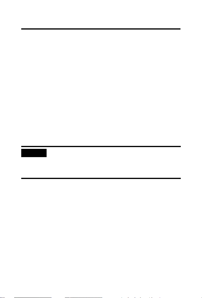
1. Align the circuit board with the top and bottom chassis guides.
Printed Circuit Board
20861-M
Figure 1 Circuit Board Alignment
Publication
1756-IN595A-EN-P - March 2004
SSI Servo Module 7
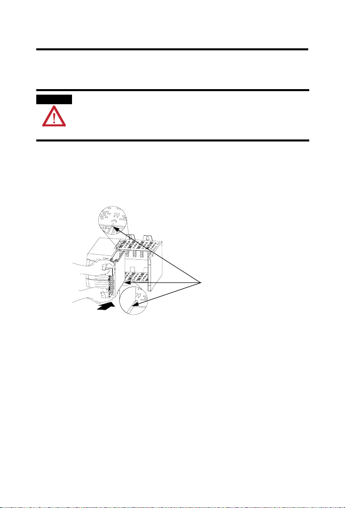
2. Slide the module into the chassis until module tabs ‘click’.
Locking Tab
20862-M
Figure 2 Module Locking Tabs
Keying the Module and Removable Terminal Block/Interface Module
Use the wedge-shaped keying tabs and U-shaped keying bands to prevent
connecting the wrong wires to your module.
Key positions on the module that correspond to unkeyed positions on the
RTB. For example, if you key the first position on the module, leave the first
position on the RTB unkeyed.
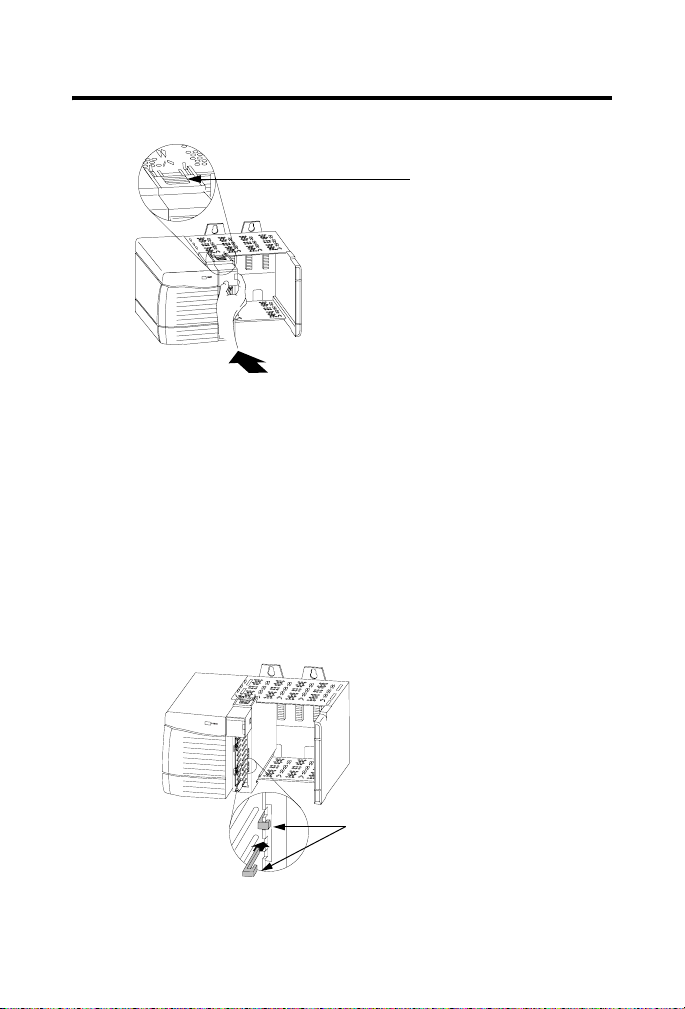
1. To key the module, insert the U-shaped band, as shown.
Figure 3 Keying Band
U-shaped
bands
20850–M
Publication
1756-IN595A-EN-P - March 2004
8 SSI Servo Module
2. Push the band until it snaps in place.
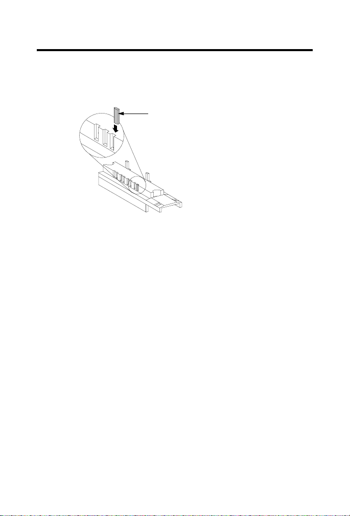
3. To key the RTB or IFM, insert the wedge-shaped tab with rounded
edge first, as shown.
Wedge-shaped tab
20851–M
Figure 4 Keying Band
4. Push the tab until it stops.
Reposition the tabs to rekey future module applications.
Wiring a Removable Terminal Block (RTB)
Your 1756-M02AS module uses two types of RTBs (each RTB comes with
housing) to connect wiring.
• Cage clamp - Catalog number 1756-TBCH
• Spring clamp - Catalog number 1756-TBS6H
Publication
1756-IN595A-EN-P - March 2004
Loading...