How it Works
Log In / Sign Up
Buy Points
How it Works
FAQ
Contact Us
Questions and Suggestions
Users
Rockwell Automation
Loading...
#
1405-M610
1405-M620
1407-CGCM
1408-EMxx
3
1408-UPxx
140EX
7
140EX-HE-RCB
140EX-HE-RMB
140G
140G-Fx
140G-G-EAB1B
140G-G-EAM1B
140G-G-EOPx
140G-G-EP3
140G-G-PRA
140G-G-TLCxtion
140G-G-UVx
140G-Gx-MG-Gx
140G-H-xxxx
2
140G-Ix
140G-Jx-MG-Jx
140G-K-EAM1A
2
140G-K-ECOPxe
140G-K-EXS3-EXS4
140G-K-PB3L-PB4L
140G-K-RMB
140G-K-RMX
140G-KTFx
140G-K-TLA
140G-K-TPA
140G-M-EAM
2
140G-M-ECM
140G-M-Fx
140G-M-RMB
140G-M-RMX
140G-M-TC3H
140G-M-TPA
140G-Mx-MG
140G-N7
140G-N8
140G-N-ECM
140G-N-EP
140G-N-NS
140G-N-PL
140G-N-RMB
140G-NRPx-RR
140G-N-SINT
140G-NS-PL
140G-NS-SCMx
140G-NTH3-E1
140G-NTK-E12
140G-Nx-NSx
2
140G-R-SCMx
140G-R-SNCx
2
140G-R-TLC63
140G-R-TLV3
140G-Rx
2
140G-x-EXT3
140G-x-MTL63
140M
4
140M-C2x
140M-C-M3
140M-C-TE1
140M-D8E
140M-F
140MG-H8E-J8Ex
140MX-C
140MX-C-ASAR01M01
140MX-C-DH
140U
140U H-Frame
3
140U-H-NH21
140U J-Frame
2
140U K-Frame
4
140U-K-NH12
140U-K-NVMxxx
140U-M-NH12
140U-M-NVMxxx
140U N-Fame
140U N-Frame
2
140U Q
11
140U-Q-NVMxxx
140U-xxx
3
1413-CAP-ME-PE
1413-ME-PEA
1414-CC20PTWZB
1414-CCZxxxxxxx
1414-CHDxxxxx
1414-CLMxxxxx
1414-CPNxxxxx
1414-CPZxxxxx
1414-CTIxxxxx
1414-CTQxxxxx
1414-CTZxx
1414-IFZ35FGDAA
1414-IHZxxxxx
1414-INZ10ZXPBP
1414-IPZxxxxx
1414-ISZxxxxx
1414-ITExxxxx
Loading...
Loading...
Nothing found
140G-NTK-E12
User Manual
41 pgs
1.54 Mb
0
Table of contents
Loading...
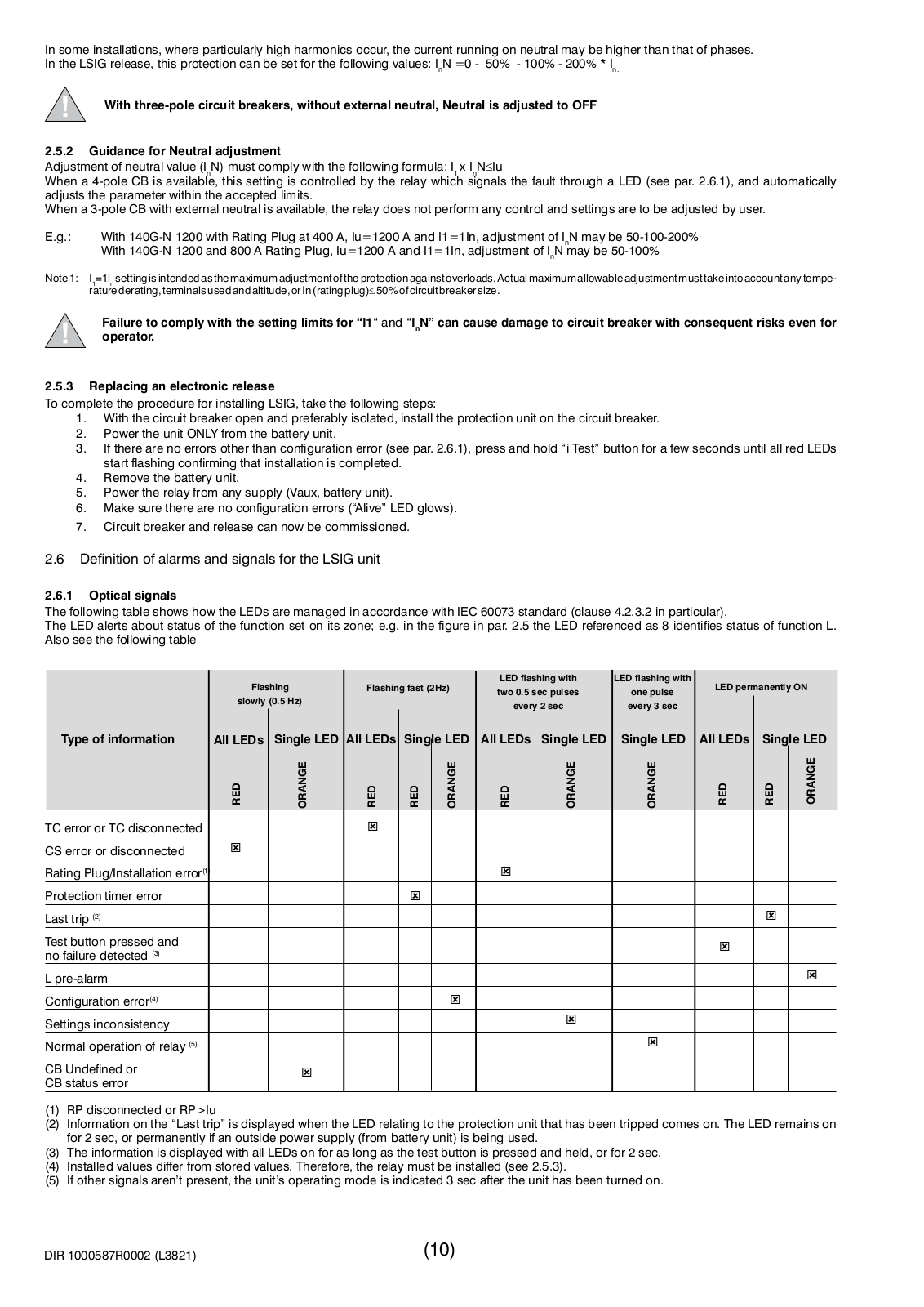
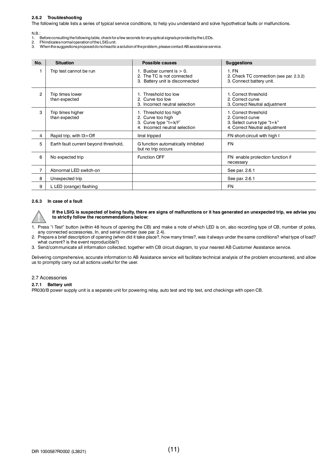
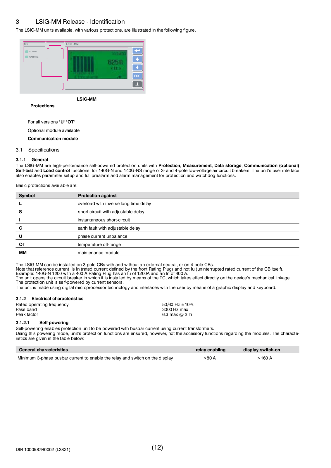
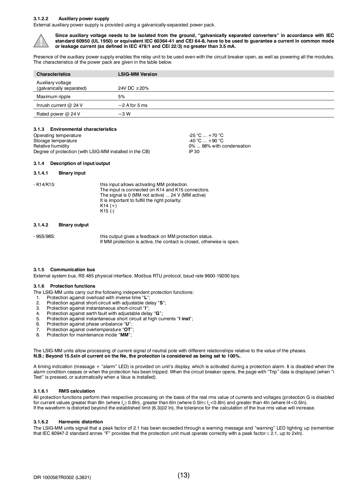
Rockwell Automation 140G-NTK-E12 User Manual
...
Rockwell Automation User Manual
Download
Specifications and Main Features
Frequently Asked Questions
User Manual
Download
Loading...
+
hidden pages
Unhide
You need points to download manuals.
1 point = 1 manual.
You can buy points or you can get point for every manual you upload.
Buy points
Upload your manuals