


USER MANUAL FOR SERIES B
SMC™-Flex
BULLETIN 150
Important User Information Because of the variety of uses for the products described in this publication, those responsible for the application and use of this control equipment must
satisfy themselves that all necessary steps have been taken to assure that each application and use meets all performance and safety requirements, including any applicable laws, regulations, codes and standards.
The illustrations, charts, sample programs and layout examples shown in this guide are intended solely for purposes of example. Since there are many variables and requirements associated with any particular installation, Allen-Bradley does not assume responsibility or liability (to include intellectual property liability) for actual use based upon the examples shown in this publication.
Allen-Bradley publication SGI-1.1, Safety Guidelines for the Application, Installation and Maintenance of Solid-State Control (available from your local Allen-Bradley office), describes some important differences between solid-state equipment and electromechanical devices that should be taken into consideration when applying products such as those described in this publication.
Reproduction of the contents of this copyrighted publication, in whole or part, without written permission of Rockwell Automation, is prohibited.
Throughout this manual we use notes to make you aware of safety considerations:
ATTENTION |
Identifies information about practices or circumstances |
|
that can lead to personal injury or death, property damage |
||
|
||
|
or economic loss |
!
Attention statements help you to:
•identify a hazard
•avoid a hazard
•recognize the consequences
|
Identifies information that is critical for successful |
|
IMPORTANT |
||
application and understanding of the product. |
||
|
||
|
||
|
|
Trademark List
Accu-Stop, Allen-Bradley Remote I/O, RSNetworx, PLC, PowerFlex, SLC, SMC, SMC-2, SMC-Flex, SMC PLUS, SMC Dialog Plus, SMB, and STC are trademarks of Rockwell Automation. ControlNet is a trademark of ControlNet International, Ltd. DeviceNet and the DeviceNet logo are trademarks of the Open Device Vendors Association (ODVA). Ethernet is a registered trademark of Digital Equipment Corporation, Intel, and Xerox Corporation. Modbus is a trademark or registered trademark of Schneider Automation Inc. Profibus is a registered trademark of Profibus International.
European Communities (EC)
Directive Compliance
If this product has the CE mark it is approved for installation within the European Union and EEA regions. It has been designed and tested to meet the following directives.
EMC Directive
This product is tested to meet the Council Directive 89/336/EC Electromagnetic Compatibility (EMC) per EN/IEC 60947-4-2.
This product is intended for use in an industrial environment.
Low Voltage Directive
This product is tested to meet Council Directive 73/23/EEC Low Voltage, per EN/IEC 60947-4-2.
This equipment is classified as open equipment and must be mounted in an enclosure during operation to provide safety protection.
Notes

Table of Contents
Chapter 1
Product Overview
Chapter 2
Installation
Other Related Documents ........................................................................... |
1-1 |
Description ................................................................................................. |
1-1 |
Operation .................................................................................................... |
1-2 |
Modes of Operation (Standard) .................................................................... |
1-2 |
Soft Start .............................................................................................. |
1-2 |
Selectable Kickstart .............................................................................. |
1-3 |
Current Limit Start ................................................................................ |
1-3 |
Dual Ramp Start ................................................................................... |
1-4 |
Full Voltage Start .................................................................................. |
1-4 |
Preset Slow Speed ............................................................................... |
1-5 |
Linear Speed Acceleration..................................................................... |
1-6 |
Soft Stop .............................................................................................. |
1-7 |
Control Options ........................................................................................... |
1-8 |
Modes of Operation (Pump Control) ............................................................. |
1-8 |
Pump Control Option ............................................................................ |
1-8 |
Modes of Operation (Braking Control) .......................................................... |
1-9 |
SMB Smart Motor Braking Option ......................................................... |
1-9 |
Accu-Stop Option ............................................................................... |
1-10 |
Slow Speed with Braking Option ......................................................... |
1-10 |
Protection and Diagnostics ........................................................................ |
1-11 |
Overload ............................................................................................ |
1-11 |
Underload ........................................................................................... |
1-11 |
Undervoltage ...................................................................................... |
1-13 |
Overvoltage ........................................................................................ |
1-13 |
Unbalance .......................................................................................... |
1-13 |
Stall Protection and Jam Detection ..................................................... |
1-14 |
Ground Fault ...................................................................................... |
1-15 |
Ground Fault Trip ............................................................................... |
1-16 |
Ground Fault Alarm ............................................................................ |
1-16 |
Thermistor/PTC Protection .................................................................. |
1-17 |
PTC Trip ............................................................................................. |
1-17 |
Excessive Starts/Hour ......................................................................... |
1-18 |
Overtemperature ................................................................................ |
1-18 |
Open Gate .......................................................................................... |
1-18 |
Line Faults ......................................................................................... |
1-18 |
Metering ................................................................................................... |
1-19 |
I/O ............................................................................................................ |
1-19 |
Communication ......................................................................................... |
1-20 |
Programming ............................................................................................ |
1-20 |
Status Indication ....................................................................................... |
1-21 |
Degree of Protection ................................................................................... |
2-1 |
Receiving .................................................................................................... |
2-1 |
Unpacking ................................................................................................... |
2-1 |
Inspecting ................................................................................................... |
2-1 |
Storing ........................................................................................................ |
2-1 |
Chapter 3
Wiring
Chapter 4
Programming
Lifting ......................................................................................................... |
2-2 |
General Precautions .................................................................................... |
2-3 |
Heat Dissipation .......................................................................................... |
2-3 |
Enclosures .................................................................................................. |
2-4 |
Mounting .................................................................................................... |
2-5 |
Power Factor Correction Capacitors .......................................................... |
2-12 |
Protective Modules ................................................................................... |
2-13 |
Motor Overload Protection ......................................................................... |
2-13 |
Two-speed Motors ............................................................................. |
2-13 |
Multi-motor Protection ....................................................................... |
2-13 |
Electromagnetic Compatibility (EMC) ......................................................... |
2-14 |
Enclosure ........................................................................................... |
2-14 |
Wiring ................................................................................................ |
2-14 |
Additional Requirements .................................................................... |
2-14 |
Terminal Locations ..................................................................................... |
3-1 |
Power Structure .......................................................................................... |
3-3 |
Power Wiring ....................................................................................... |
3-3 |
Line Connected .................................................................................... |
3-4 |
Delta Connected .................................................................................. |
3-4 |
Power Lugs ................................................................................................ |
3-5 |
Control Power ............................................................................................. |
3-7 |
Control Wiring ...................................................................................... |
3-7 |
Controllers rated 5…480 A .................................................................. |
3-7 |
Controllers rated 625…1250 A ............................................................ |
3-7 |
Control Wire Specifications ................................................................ |
3-11 |
Fan Power ................................................................................................ |
3-11 |
Fan Terminations ............................................................................... |
3-11 |
Control Terminal Designations .................................................................. |
3-12 |
Standard Controller Wiring Diagrams ........................................................ |
3-13 |
Soft Stop, Pump Control, and SMB Smart Motor Braking ........................... |
3-24 |
Preset Slow Speed .................................................................................... |
3-28 |
Slow Speed with Braking .......................................................................... |
3-30 |
Sequence of Operation .............................................................................. |
3-31 |
Special Application Considerations ............................................................ |
3-36 |
Use of Protective Modules ..................................................................... |
36 |
Multi-motor Applications ........................................................................... |
3-38 |
SMC-Flex Controller as a Bypass to an AC Drive ....................................... |
3-39 |
SMC-Flex Controller with a Bulletin 1410 Motor Winding Heater ............... |
3-40 |
Overview .................................................................................................... |
4-1 |
Keypad Description ..................................................................................... |
4-1 |
Programming Menu .................................................................................... |
4-1 |
Password .................................................................................................... |
4-5 |
Parameter Management ............................................................................. |
4-6 |
Random Access Memory (RAM) ........................................................... |
4-6 |
Read-only Memory (ROM) .................................................................... |
4-6 |
Electrically Erasable Programmable Read-only Memory (EEPROM) ....... |
4-6 |
Parameter Modification................................................................................ |
4-7 |
Soft Start .................................................................................................... |
4-8 |
Chapter 5
Metering
Chapter 6
Optional HIM Operation
Chapter 7
Communications
Chapter 8
Diagnostics
Current Limit Start ...................................................................................... |
4-8 |
Dual Ramp Start .......................................................................................... |
4-9 |
Full Voltage Start ....................................................................................... |
4-10 |
Linear Speed ............................................................................................. |
4-10 |
Programming Parameters ......................................................................... |
4-11 |
Standard ............................................................................................ |
4-11 |
Pump Control ..................................................................................... |
4-12 |
Braking Control .................................................................................. |
4-12 |
Basic Set Up ............................................................................................. |
4-14 |
Motor Protection ....................................................................................... |
4-15 |
Example Settings ...................................................................................... |
4-16 |
Undervoltage ...................................................................................... |
4-16 |
Overvoltage ........................................................................................ |
4-16 |
Jam ................................................................................................... |
4-16 |
Underload .......................................................................................... |
4-16 |
Overview ..................................................................................................... |
5-1 |
Viewing Metering Data ................................................................................ |
5-1 |
Overview ..................................................................................................... |
6-1 |
Human Interface Module ............................................................................. |
6-1 |
Standard .............................................................................................. |
6-1 |
Pump Control ....................................................................................... |
6-2 |
Braking Control .................................................................................... |
6-2 |
Overview ..................................................................................................... |
7-1 |
Communication Ports .................................................................................. |
7-1 |
Human Interface Module ............................................................................. |
7-2 |
Keypad Description .............................................................................. |
7-2 |
Connecting the Human Interface Module to the Controller .................... |
7-4 |
HIM Control Enable ............................................................................... |
7-4 |
Control Enable ............................................................................................. |
7-6 |
Loss of Communication and Network Faults ................................................ |
7-6 |
SMC-Flex Specific Information .................................................................... |
7-6 |
Default Input/Output Configuration .............................................................. |
7-7 |
Variable Input/Output Configuration ............................................................. |
7-7 |
SMC — Flex Bit Identification ..................................................................... |
7-8 |
Reference/Feedback ................................................................................... |
7-9 |
Parameter Information ................................................................................ |
7-9 |
Scale Factors for PLC Communication ......................................................... |
7-9 |
Read Example ...................................................................................... |
7-9 |
Write Example ...................................................................................... |
7-9 |
Display Text Unit Equivalents .................................................................... |
7-10 |
Configuring DataLinks ............................................................................... |
7-10 |
Rules for Using DataLinks .................................................................. |
7-10 |
Updating Firmware .................................................................................... |
7-10 |
Overview ..................................................................................................... |
8-1 |
Protection Programming ....................................................................... |
8-1 |
Chapter 9
Troubleshooting
Appendix A
Specifications
Fault Display ............................................................................................... |
8-1 |
Clear Fault .................................................................................................. |
8-2 |
Fault Buffer ................................................................................................. |
8-2 |
Fault Codes .......................................................................................... |
8-3 |
Fault and Alarm Auxiliary Indication for Fault or Alarm ................................ |
8-3 |
Fault Definitions .......................................................................................... |
8-4 |
Introduction ................................................................................................ |
9-1 |
Power Module Check .................................................................................. |
9-7 |
Shorted SCR Test ................................................................................. |
9-7 |
Functional Design Specifications ................................................................. |
A-1 |
Electrical Ratings ........................................................................................ |
A-2 |
Short Circuit Protection ............................................................................... |
A-3 |
Environmental ............................................................................................. |
A-5 |
Mechanical ................................................................................................. |
A-5 |
Other .......................................................................................................... |
A-6 |
Approximate Dimensions and Shipping Weights .......................................... |
A-6 |
Open Type Controllers .......................................................................... |
A-6 |
Enclosed Type Line-Connected Controllers ........................................... |
A-7 |
Appendix B |
Parameter Information ................................................................................ |
B-1 |
Parameter Information |
|
|
Appendix C |
Renewal Parts ............................................................................................ |
C-1 |
Renewal Parts |
|
|
Appendix D |
Contactor Replacement Installation Instructions for |
|
Accessories |
625…1250 A units ...................................................................................... |
D-1 |
Appendix E |
Accessories ................................................................................................ |
E-1 |
Accessories |
|
|
Appendix F |
Renewal Part Cross Reference .................................................................... |
F-1 |
Renewal Parts Cross Reference |
|
|

Chapter 1
Product Overview
Other Related Documents |
• |
Quick Start — Publication 150-QS001_ -EN-P |
|
|
• |
Renewal Part Instructions — 41053-277-01 |
(5…85 A) |
|
|
41053-328-01 |
(108…135 A) |
|
|
41053-228-01 |
(201…480 A) |
|
|
41053-367-01 |
(625…1250 A) |
|
• Selection Guide — Publication 150-SG009_ -EN-P |
||
|
• Application Guide — Publication 150-AT002_ -EN-P |
||
Description |
The SMC™-Flex controller offers a full range of starting modes as |
||
|
standard: |
|
|
|
• Soft Start with Selectable Kickstart |
|
|
|
• Current Limit with Selectable Kickstart |
|
|
|
• Dual Ramp Start with Selectable Kickstart |
|
|
|
• |
Full Voltage Start |
|
|
• |
Preset Slow Speed |
|
|
• Linear Speed Acceleration with Selectable Kickstart (requires |
||
|
|
Tach feedback) |
|
|
• |
Soft Stop |
|
|
Other features that offer further user benefit include: |
|
|
|
• |
Expanded protective features |
|
|
• |
Metering |
|
|
• |
I/O |
|
|
• |
Communication capability |
|
|
Innovative starting and stopping options provide enhanced |
||
|
performance: |
|
|
|
• |
Pump Control |
|
|
• |
Braking Control |
|
|
|
• Smart Motor Braking (SMB™) |
|
|
|
• Accu-Stop™ |
|
|
|
• Slow Speed with Braking |
|
These modes, features, and options are further described in this chapter.
Latest revision
1-2 |
Product Overview |
|
|
Operation
Modes of Operation (Standard)
The SMC-Flex controller can operate standard squirrel-cage induction motors rated 1…1250 A or Star-delta (wye-delta) type motors rated 1.8…1600 A; up to 690V AC, 50/60 Hz. Depending upon the controller type ordered, the control power input can range from 100…240V AC to 24V AC/DC. Please verify voltage on product, before applying power.
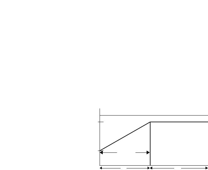
Soft Start
This mode has the most general application. The motor is given an initial torque setting, which is user-adjustable from 0…90% of locked rotor torque. From the initial torque level, the output voltage to the motor is steplessly increased during the acceleration ramp time. The acceleration ramp time is user-adjustable from 0…30 seconds. If the SMC-Flex controller senses that the motor has reached the up-to- speed condition during the voltage ramp operation, the internal bypass contactor will be pulled in.
Figure 1.1 Soft Start
|
|
Current Limit |
100% |
|
|
Percent Voltage |
|
|
Initial |
Ramp Time |
|
Torque |
|
|
|
Start |
Run |
Time in Seconds
Kickstart is also available with Soft Start.
Product Overview |
1-3 |
|
|
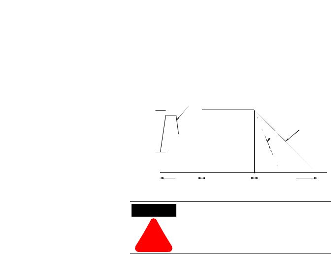
Selectable Kickstart
This feature provides a boost at startup to break away loads that require a pulse of high torque to get started. This is intended to provide a pulse of current that is selectable from 0…90% of locked rotor torque. Selectable kickstart is user-adjustable from
0.0…2.0 seconds.
Figure 1.2 Selectable Kickstart
Percent
Voltage
Selectable Kickstart
100%
Coast-to-rest
Soft Stop
Initial
Torque
Start 
 Run
Run 
 Soft Stop
Time (seconds)
Current Limit Start
This starting mode provides a true current limit start; it is used when limiting maximum starting current is necessary. The Current Limit level is user-adjustable from 50…600% of the motor full load ampere rating; and the current limit time is user-adjustable from 0…30 seconds. If the SMC-Flex controller senses that the motor has reached the up-to-speed condition during the current limit starting mode, the internal bypass contactor will be pulled in.
Figure 1.3 Current Limit Start
600%
Percent Full
Load Current
50%
Start
Time (seconds)
Kickstart is also available with Current Limit Start.

1-4 |
Product Overview |
|
|
Dual Ramp Start
This starting mode is useful on applications that have varying loads (and therefore varying starting torque requirements). Dual Ramp Start allows the user to select between two separate start profiles with separately adjustable ramp times and initial torque settings.
Figure 1.4 Dual Ramp Start
|
|
Current Limit 2 |
|
|
Current Limit 1 |
|
100% |
Ramp #2 |
Voltage |
Initial |
|
Torque #2 |
|
|
Percent |
|
Ramp #1 |
Initial |
|
|
|
Torque #1 |
|
 Start #1
 Run #1
Start #2 Run #2
Time in Seconds
Dual Ramp Start is available only with the standard controller.
Full Voltage Start
This starting mode is used for applications requiring across-the-line starting. The output voltage to the motor will reach full voltage within 1/4 second.
Figure 1.5 Full Voltage Start
100%
Percent Voltage
Time in Seconds
Product Overview |
1-5 |
|
|
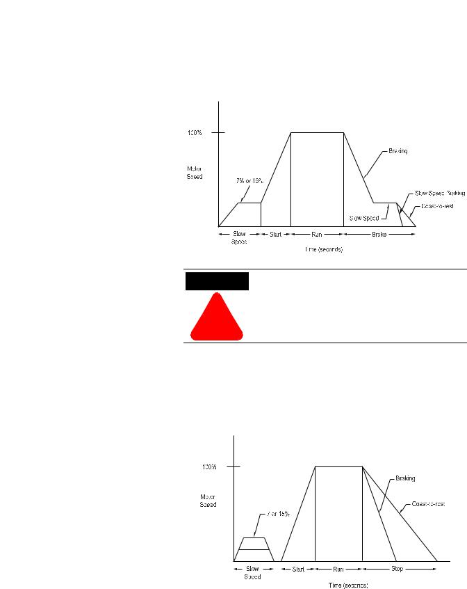
Preset Slow Speed
This option can be used in applications that require a slow speed jog for general purpose positioning. Preset Slow Speed provides either 7% of base speed (low) or 15% of base speed (high) settings in the forward direction. Reverse can also be programmed and offers 10% of base speed (low) and 20% of base speed (high) settings.
Figure 1.6 Preset Slow Speed
100% |
|
|
Motor |
|
|
Speed |
|
|
Forward |
|
|
15% - High |
|
|
7% - Low |
|
|
Time (seconds) |
Start |
Run |
|
10% - Low
20% - High
Reverse
ATTENTION Slow speed running is not intended for continuous operation due to reduced motor cooling.
!
1-6 |
Product Overview |
|
|
Linear Speed Acceleration
The SMC-Flex has the ability to control the motor speed during starting and stopping maneuvers. A tach input (0…5V DC) is required to perform this start mode. The start time is selectable from 0…30 seconds and determines the time the motor will ramp from 0 speed to full speed. Kickstart is available with this option.
Figure 1.7 Linear Speed Acceleration
Percent
Speed
100%
Start 
 Run
Run 
 Stop
Stop 
Time (seconds)
Kickstart is also available with Linear Speed Acceleration.
ATTENTION Linear Stop is not intended to be used as an emergency stop. Refer to the applicable standards
!for emergency stop requirements.
The Linear Stop does not need to be set up even if the linear start has been programmed. The Linear Stop can not brake the motor/load and reduce the stopping time.
Product Overview |
1-7 |
|
|
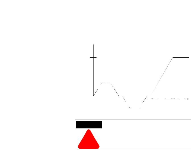
Soft Stop
This option can be used in applications that require an extended stop time. The voltage ramp down time is user-adjustable from
0…120 seconds and is adjusted independently from the starting time. The load will stop when the output voltage drops to a point where the load torque is greater than the developed motor torque.
Figure 1.8 Soft Stop
Percent
Voltage
Selectable Kickstart
100%
Coast-to-rest
Soft Stop
Initial
Torque
Start |
|
|
|
Run |
|
|
|
Soft Stop |
|
|
|
|
|||||
|
|
|
Time (seconds) |
|
|
|
||
ATTENTION Soft Stop is not intended to be used as an emergency stop. Refer to the applicable standards for
!emergency stop requirements.

1-8 |
Product Overview |
|
|
Control Options
Modes of Operation
(Pump Control)
The SMC-Flex controller offers the control options described below.
Important: The options listed in this section are mutually exclusive and must be specified when ordering. An existing controller may be upgraded to another control option by replacing the control module. Consult your local Allen-Bradley distributor.
Pump Control Option
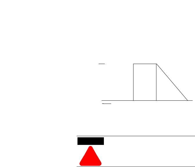
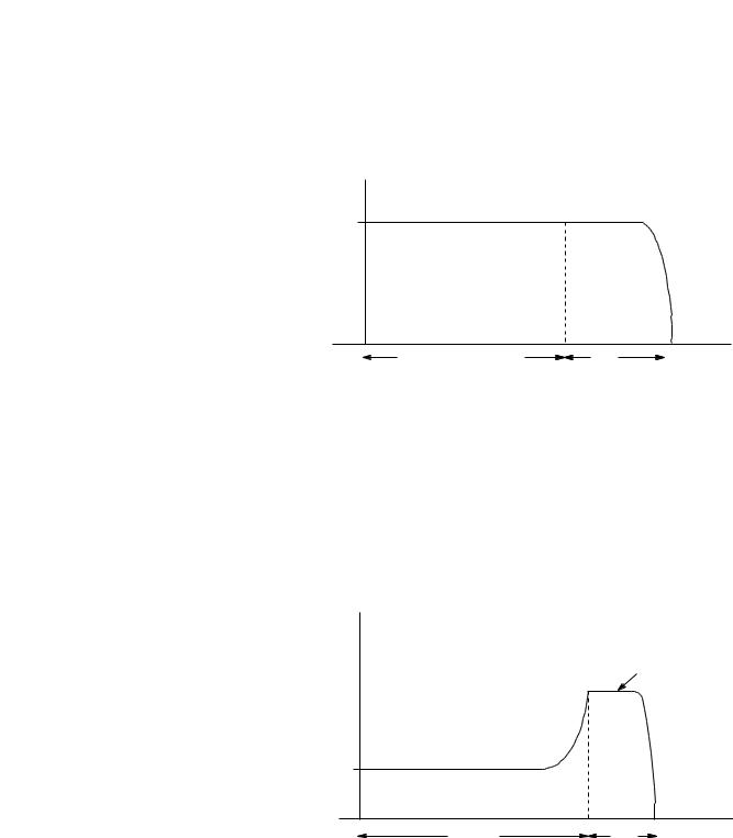
This option reduces surges during the starting and stopping of a centrifugal pump by smoothly accelerating and decelerating the motor. The microprocessor analyzes the motor variables and generates commands that control the motor and reduce the possibility of surges occurring in the system.
The starting time is programmable from 0…30 seconds, and the stopping time is programmable from 0…120 seconds.
Figure 1.9 Pump Control Option
100%
Motor Speed
Pump Start |
|
|
|
Run |
|
|
|
Pump Stop |
Ramp Time |
|
|
Time in Seconds |
|
Stop Time |
|||
|
|
|
|
|
||||
Kickstart is also available with Pump Control.
ATTENTION Pump stopping is not intended to be used as an emergency stop. Refer to the applicable standard for
!emergency stop requirements.
ATTENTION
!
Pump stopping may cause motor heating depending on the mechanical dynamics of the pumping system. Therefore, select the lowest stopping time setting that will satisfactorily stop the pump.

Product Overview |
1-9 |
|
|
Modes of Operation
(Braking Control)
SMB™ Smart Motor Braking Option
This option can be used in applications that require reduced stopping times. The SMC-Flex controller incorporates a microprocessor-based system that applies braking current to a motor without any additional equipment. This option offers a user-adjustable braking current setting from 0% to 400% of the motor’s full load current rating. Further, it provides automatic shut-off at zero speed detection.
Figure 1.10 SMB Smart Motor Braking Option
100% |
Smart Motor |
|
Braking |
Motor Speed |
Coast-to-Rest |
|
|
|
Stop |
|
Time |
Start |
|
Run |
|
|
|
Brake |
|
Automatic Zero |
|
|
|
|
|||||
|
Time in Seconds |
|
|
|
Speed Shut-Off |
|||
|
|
|
|
|
||||
Note: All braking current settings in the range of 1…100% will provide 100% braking current to the motor.
ATTENTION SMB Smart Motor Braking is not intended to be used as an emergency stop. Refer to applicable standards
!for emergency stop requirements.
1-10 |
Product Overview |
|
|
Accu-Stop™ Option
This option combines the benefits of the SMB Smart Motor Braking and Preset Slow Speed options. For general purpose positioning, the Accu-Stop option provides a brake from full speed to the preset slow speed setting, then brakes to stop.
Figure 1.11 Accu-Stop Option
ATTENTION
!
Accu-Stop and Slow Speed with Braking are not intended to be used as an emergency stop. Refer to applicable standards for emergency stop requirements.
Slow Speed with Braking Option
The Slow Speed with Braking option provides a jog speed for process set-up and braking-to-stop at the end of the cycle.
Figure 1.12 Slow Speed with Braking Option

|
Product Overview |
1-11 |
|
|
|
Protection and Diagnostics |
The SMC-Flex controller provides the protective and diagnostic |
|
|
features described below. |
|
Overload
The SMC-Flex controller meets applicable requirements as a motor overload protective device. Thermal memory provides added protection and is maintained even when control power is removed. The built-in overload controls the value stored in Parameter 12, Motor Thermal Usage; an Overload Fault will occur when this value reaches 100%. The programming parameters below provide application flexibility and easy setup.
Parameter |
Range |
|
|
Overload Class |
Off, 10, 15, 20, 30 |
Overload Reset |
Manual – Auto |
|
|
Motor FLC |
1.0…2200 A |
|
|
Service Factor |
0.01…1.99 |
Notes: (1) The factory default setting for Overload Class, which is 10, enables overload protection. The motor’s full load current rating must be programmed to properly set overload protection.
(2)Automatic reset of an overload fault requires the start input to be cycled in a 2-wire control scheme.
The trip rating is 117% of the programmed FLC.
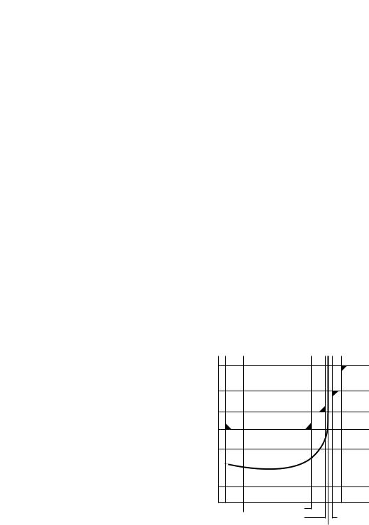
Figure 1.13 and Figure 1.14 provide the overload trip curves for the available trip classes.
Underload
Utilizing the underload protection of the SMC-Flex controller, motor operation can be halted if a sudden drop in current is sensed.
The SMC-Flex controller provides an adjustable underload trip setting from 0…99% of the programmed motor full load current rating. Trip delay time can be adjusted from 0…99 seconds.
Underload protection is disabled during slow speed and braking operations.

1-12 |
Product Overview |
|
|
Figure 1.13 Overload Trip Curves
Class 10 |
Class 15 |
Class 20 |
Class 30 |
|
1000.0 |
|
|
|
|
|
|
|
(seconds) |
100.0 |
|
|
|
|
|
|
|
|
|
|
|
|
|
|
|
|
Trip Time |
10.0 |
|
|
|
|
|
|
|
|
|
|
|
|
|
|
|
|
Approximate |
1.0 |
|
|
|
|
|
|
|
|
|
|
|
|
|
|
|
|
|
0.1 |
|
|
|
|
|
|
|
|
1 |
2 |
3 |
4 |
5 |
6 |
7 |
8 910 |
Multiples of FLC
|
10000.0 |
|
|
|
|
|
|
|
|
10000.0 |
|
|
|
|
|
|
|
|
|
|
|
|
|
|
|
|
|
|
|
|
|
|
|
(seconds) |
1000.0 |
|
|
|
|
|
|
|
(seconds) |
1000.0 |
|
|
|
|
|
|
|
|
|
|
|
|
|
|
|
|
|
|
|
|
|||
|
|
|
|
|
|
|
|
|
|
|
|
|
|
|
||
Trip Time |
100.0 |
|
|
|
|
|
|
|
Trip Time |
100.0 |
|
|
|
|
|
|
|
|
|
|
|
|
|
|
|
|
|
|
|
|
|
||
Approximate |
10.0 |
|
|
|
|
|
|
|
Approximate |
10.0 |
|
|
|
|
|
|
|
|
|
|
|
|
|
|
|
|
|
|
|
|
|
||
|
1.0 |
2 |
3 |
4 |
5 |
6 |
7 |
8 9 10 |
|
1.0 |
2 |
3 |
4 |
5 |
6 |
7 8 910 |
|
1 |
|
1 |
Multiples of FLC |
Multiples of FLC |
|
10000.0 |
|
|
|
|
|
|
(seconds) |
1000.0 |
|
|
|
|
|
|
|
|
|
|
|
|
|
|
Trip Time |
100.0 |
|
|
|
|
|
|
|
|
|
|
|
|
|
|
Approximate |
10.0 |
|
|
|
|
|
|
|
|
|
|
|
|
|
|
|
1.0 |
2 |
3 |
4 |
5 |
6 |
7 8 9 10 |
|
1 |
Multiples of FLC
3- |
|
|
|
|
|
for 3- |
|
|
|
||||
Approximateate triptimefor3-phasebalanced |
|
|
|
|
|
Approximatetriptimefor 3-phasebalanced |
condition from cold start. |
|
|
|
|
|
condition from hot start. |
condition from cold start. |
|
|
|
|
|
condition from cold start. |
Figure 1.14 Restart Trip Curves after Auto Reset |
|
|
|
100000 |
|
|
1000 |
|
Seconds |
100 |
|
|
|
|
|
10 |
Class 10 |
|
Class 15 |
|
|
|
|
|
|
Class 20 |
|
|
Class 30 |
|
1 |
Auto Reset Times: |
|
|
Class 10 = 90s |
|
|
Class 15 = 135s |
|
|
Class 20 = 180s |
|
|
Class 30 = 270s |
|
0 |
|
|
100% |
1000% |
Percent Full Load Current Setting
Product Overview |
1-13 |
|
|
Undervoltage
Utilizing the undervoltage protection of the SMC-Flex, motor operation can be halted if a sudden drop in voltage is detected.
The SMC-Flex controller provides an adjustable undervoltage trip setting from 0…99% of the programmed motor voltage. Trip delay time can be adjusted from 0…99 seconds.
An alarm (pre-fault) indication level can be programmed to indicate the unit is getting close to faulting. The alarm modification information is displayed through the LCD, HIM, Communication (if applicable) and alarm contact closing.
Overvoltage
Utilizing the overvoltage protection of the SMC-Flex, motor operation can be halted if a sudden increase in voltage is detected.
The SMC-Flex controller provides an adjustable overvoltage trip setting from 0…199% of the programmed motor voltage. Trip delay time can be adjusted from 0…99 seconds.
An alarm (pre-fault) indication level can be programmed to indicate the unit is getting close to faulting. The alarm modification information is displayed through the LCD, HIM, Communication (if applicable) and alarm contact closing.
Unbalance
The SMC-Flex is able to detect an unbalance in line voltages. Motor operation can be halted if the unbalance is greater than the desired range.
The SMC-Flex controller provides an adjustable unbalance setting from 0…25% of the line voltages. Trip delay time can be adjusted from 0…99 seconds.
An alarm (pre-fault) indication level can be programmed to indicate the unit is getting close to faulting. The alarm modification information is displayed through the LCD, HIM, Communication (if applicable) and alarm contact closing.
Undervoltage, overvoltage, and voltage unbalance protection are disabled during braking operation.
1-14 |
Product Overview |
|
|
Stall Protection and Jam Detection
The SMC-Flex controller provides both stall protection and jam detection for enhanced motor and system protection.
•Stall protection is user-adjustable from 0.0…10.0 seconds (in addition to the ramp time programmed).
Figure 1.15 Stall Protection
600% |
|
Percent |
|
Full |
|
Load |
|
Current |
|
Programmed Start Time |
Stall |
Time (seconds)
•An alarm (pre-fault) indication level can be programmed to indicate the unit is getting close to faulting. The alarm modification information is displayed through the LCD, HIM, Communication (if applicable) and alarm contact closing.
•Jam detection allows the user to determine the jam level (up to 1000% of the motor’s FLC rating) and the delay time (up to 99.0 seconds) for application flexibility.
Figure 1.16 Jam Detection
Percent |
|
|
Full |
User Programmed Trip Level |
|
Load |
||
|
||
Current |
|
|
100% |
|
|
Running |
Jam |
Time (seconds)
Jam detection is disabled during slow speed and braking operation.
Unit will self-protect in a jam condition.

Product Overview |
1-15 |
|
|
Ground Fault
In isolated or high impedance-grounded systems, core-balanced current sensors are typically used to detect low level ground faults caused by insulation breakdowns or entry of foreign objects. Detection of such ground faults can be used to interrupt the system to prevent further damage, or to alert the appropriate personnel to perform timely maintenance.
The SMC-Flex’s ground fault detection capabilities require the use of external sensor. Installation of this sensor allows the option of enabling Ground Fault Trip, Ground Fault Alarm, or both.
For the 5…480 Amp devices, the recommended sensor is a Cat. No. 825-CBCT core balance current transformer for 1…5 A corebalanced ground fault protection.
For the 625…1250 A devices, the recommended sensor is shown below and provides 5…25 A core-balanced ground fault protection.
• |
Manufacturer: |
Allen-Bradley |
• |
Description: |
600 Volt-Rated Current Transformer |
•Catalog Number: 1411-126-252
• Ratio: |
2500:5 |
Figure 1.17
1
1 2
1
BLACK
WHITE
SHIELD
SHIELD
BLACK
WHITE
Customer supplied.
Cat. No. 825-CBCT or Flex-Core Cat. No. 126-252
Note: When connecting the ground fault sensors, the secondary of the CT should be shorted until the connection to the Flex control module is completed.

1-16 |
Product Overview |
|
|
Ground Fault Trip
The SMC-Flex will trip with a ground fault indication if:
•No other fault currently exists
•Ground fault protection is enabled
•GF Inhibit Time has expired
•GF Current is equal to or greater than the GF Trip Level for a time period greater than the GF Trip Delay
Parameter 75, Gnd Flt Inh Time, allows the installer to inhibit a ground fault trip from occurring during the motor starting sequence and is adjustable from 0…250 seconds.
Parameter 74, Gnd Flt Delay, allows the installer to define the time period a ground fault condition must be present before a trip occurs. It is adjustable from 0.1…250 seconds.
Parameter 73, Gnd Flt Level, allows the installer to define the ground fault current at which the SMC-Flex will trip. It is adjustable from 1.0…5.0 A or 5.0…25 A, depending on the service size.
Important: The ground fault inhibit timer starts after the maximum phase of load current transitions from 0 A to 30% of the device’s minimum FLA Setting or the GF Current is greater than or equal to 0.5 A. The SMC-Flex does not begin monitoring for a ground fault condition until the
Gnd Flt Inh Time expires.
Ground Fault Alarm
The SMC-Flex will indicate a Ground Fault Alarm if:
•No warning currently exists
•Ground fault alarm is enabled
•GF Inhibit Time has expired
•GF Current is equal to or greater than the Gnd Flt A Lvl
Parameter 77, Gnd Flt A Lvl, allows the installer to define the ground fault current at which the SMC-Flex will indicate a warning. It is adjustable from 1.0…5.0 A or 5.0…25 A, depending on the service size.
Parameter 78, Gnd Flt A Dly, allows the installer to define the time period a ground fault alarm condition must be present before a trip occurs. It is adjustable from 0…250 seconds.
Product Overview |
1-17 |
|
|
Thermistor/PTC Protection
The SMC-Flex provides terminals 23 and 24 for the connection of positive temperature coefficient (PTC) thermistor sensors. PTC sensors are commonly embedded in motor stator windings to monitor the motor winding temperature. When the motor winding temperature reaches the PTC sensor’s temperature rating, the PTC sensor’s resistance transitions from a low to high value. Since PTC sensors react to actual temperature, enhanced motor protection can be provided to address such conditions as obstructed cooling and high ambient temperatures.
The following table defines the SMC-Flex PTC thermistor input and response ratings:
Table 1.A PTC Input Ratings
Response resistance |
3400 |
Ω ±150 Ω |
Reset resistance |
1600 |
Ω ±100 Ω |
Short-circuit Trip Resistance |
25 Ω ±10 Ω |
|
Maximum Voltage at PTC Terminals (RPTC = 4kΩ) |
< 7.5V |
|
Maximum Voltage at PTC Terminals (RPTC = open) |
30V |
|
Maximum Number of Sensors |
6 |
|
|
|
|
Maximum Cold Resistance of PTC Sensor Chain |
1500 |
Ω |
Response Time |
800 ms |
|
|
|
|
The following figure illustrates the required PTC sensor characteristics, per IEC-34-11-2.
Figure 1.18 PTC Sensor Characteristics per IEC-34-11-2
4000
1330 |
|
|
550 |
|
|
250 |
|
|
100 |
|
|
20 |
|
|
10 |
|
|
-20°C |
TNF-20K |
TNF+15K |
0°C |
TNF5K |
TNF+ 5K |
TNF
PTC Trip
The SMC-Flex will trip with a PTC indication if:
•No other fault currently exists
•PTC protection is enabled

1-18 |
Product Overview |
|
|
•The resistance across terminals 23 and 24 is either greater than the relay’s response resistance or less than the short-circuit trip resistance.
Excessive Starts/Hour
The SMC-Flex controller allows the user to program the allowed number of starts per hour (up to 99). This helps eliminate motor stress caused by repeated starting over a short time period.
Overtemperature
The SMC-Flex controller monitors the temperature of the SCRs and Bypass by using internal thermistors. When the power poles’ maximum rated temperature is reached, the unit will shut down and restart is inhibited.
An overtemperature condition can indicate inadequate ventilation, high ambient temperature, overloading, or excessive cycling. After the temperature is reduced to allowable levels, the fault can be cleared.
Open Gate
An open gate fault indicates that improper SCR firing, typically caused by an open SCR gate, has been detected on one of the power poles. Before the controller shuts down, it will attempt to start the motor a total of three times.
Line Faults
The SMC-Flex controller continually monitors line conditions for abnormal factors. Pre-start protection includes:
•Line Fault (with phase indication)
–Line voltage loss
–Missing load connection
–Shorted SCR
Running protection includes:
•Line Fault (no phase indication)
–Line voltage loss
–Missing load connection
Phase Reversal protection can be toggled either On or Off.
Phase Reversal protection is functional only at pre-start.

|
|
Product Overview |
1-19 |
|
|
|
|
Metering |
Power monitoring parameters include: |
|
|
|
• Three-phase current |
|
|
|
• Three-phase voltage |
|
|
|
• |
Power in kW |
|
|
• Power usage in kWH |
|
|
|
• |
Power factor |
|
|
• Motor thermal capacity usage |
|
|
|
• |
Elapsed time |
|
|
Notes: (1) Voltage measurement is not available during the braking |
||
|
|
operation of the SMB Smart Motor Braking, Accu-Stop, |
|
|
|
and Slow Speed with Braking control options. |
|
|
|
(2) The elapsed time and kWH values are automatically |
|
|
|
saved to memory every 12 hours. |
|
|
|
(3) Motor thermal capacity usage is determined by the built- |
|
|
|
in electronic thermal overload. An overload fault occurs |
|
|
|
when this value reaches 100%. |
|
I/O |
The SMC-Flex has the ability to accept up to two (2) inputs and |
|
|
|
four (4) outputs controlled over a network. The two inputs are |
|
|
|
controlled at terminal 16 (Option Input #1), and terminal 15 |
|
|
(Option Input #2). For these two inputs, see Chapter 4 for the parameter settings and see Chapter 7 for the bit identification.
By using these two terminals as inputs, the Stop Input will need to be programmed to meet the desired stop functionality.
The four (4) outputs are Aux #1, Aux #2, Aux #3, and Aux #4. All auxiliary contacts are programmable to the function found on page 4-14. If programmed to Network or Network NC, they can be controlled over a Network. Please see Table 7.H that defines the Logic Command Word (Control).
1-20 Product Overview
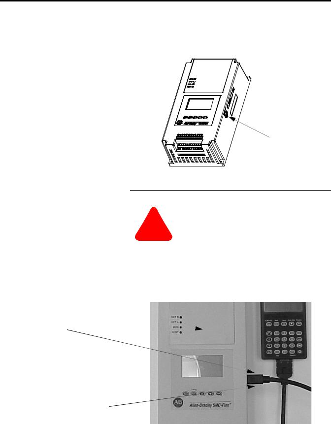
Communication |
A serial interface port (DPI) is provided as standard, which allows |
|
connection to the Bulletin 20-HIM LCD interface modules. |
|
Figure 1.19 DPI Location |
DPI
|
ATTENTION |
Two peripheral devices can be connected to the DPI. |
|
|
The maximum output current through the DPI is |
|
|
|
|
! |
280 mA. |
|
|
|
Programming |
Setup is easy with the built-in keypad and three-line, sixteen character |
|
backlit LCD. Parameters are organized in a three-level menu |
|
structure, using a text format for straightforward programming. |
|
Figure 1.20 Built-in Keypad and LCD |
Port 5 — DPI |
|
Communications |
|
Port 2 |
|
Ports 2 and 3 when two HIMs are connected with a splitter

|
|
Product Overview |
1-21 |
|
|
||
Status Indication |
Four programmable hard contact outputs are provided as standard. All |
||
|
auxiliary contacts are programmable for the following states: |
|
|
|
• |
Normal (N.O./N.C.) |
|
|
• |
Up-to-Speed (N.O./N.C.) |
|
|
• |
Alarm (N.O./N.C.) |
|
|
• |
Fault (N.O./N.C.) |
|
|
• |
Network Control (N.O./N.C.) |
|
|
• |
External Bypass (N.O.) |
|
Figure 1.21 Control Terminals
|
11 |
12 |
13 |
14 |
15 |
16 |
|
17 |
|
18 |
19 |
|
20 |
21 |
|
22 |
|||||||||||||||
|
|
|
|
|
|
|
|
|
|
|
|
|
|
|
|
|
|
|
|
|
|
|
|
|
|
|
|
|
|
|
|
|
|
|
|
|
|
|
|
|
|
|
|
|
|
|
|
|
|
|
|
|
|
|
|
|
|
|
|
|
|
|
|
|
|
|
|
|
|
|
|
|
|
|
Opt |
|
|
|
|
Stop |
|
|
|
|
|
|
|
|
|
|
|
|
|||
|
|
|
|
|
|
|
|
|
|
|
|
|
|
|
|
|
|
|
|
|
|
|
|
|
|
||||||
|
|
|
|
|
|
|
|
|
|
|
Input #1 |
|
|
|
|
Input |
|
|
|
|
|
|
|
|
|
|
|
|
|||
|
|
|
|
|
|
|
|
|
Opt |
Start |
|
|
|
|
|
|
|
|
|
|
|
|
|
||||||||
|
|
|
|
|
|
|
|
|
|
|
|
|
|
|
Aux #1 |
|
|
|
|
|
|
||||||||||
|
|
|
|
|
|
|
|
|
Input #2 |
Input |
|
|
|
|
|
|
|
|
|
||||||||||||
|
|
SMC-Flex |
|
|
|
|
|
|
|
|
|
|
|
|
|
|
|
|
|
||||||||||||
|
|
|
|
|
|
|
|
|
|
|
|
|
|
|
|
|
|
|
|
|
|
|
|
|
|
|
|||||
Control Terminals |
|
|
|
|
|
|
|
|
|
|
|
|
|
|
|
|
|
|
|
|
|
|
|
||||||||
|
|
|
|
|
|
|
|
|
|
|
|
|
|
|
|
|
|
|
|
|
|
|
|
|
|
|
|
|
|
|
|
|
23 |
24 |
25 |
26 |
27 |
28 |
|
29 |
|
30 |
31 |
|
32 |
33 |
|
34 |
|||||||||||||||
|
|
|
|
|
|
|
|
|
|
|
|
|
|
|
|
|
|
|
|
|
|
|
|
|
|
|
|
|
|
|
|
|
|
|
|
|
|
|
|
|
|
|
|
|
|
|
|
|
|
|
|
|
|
|
|
|
|||||||
|
|
|
|
|
|
|
|
|
|
|
|
|
|
|
|
|
|
|
|
|
|
|
|
|
|
|
|
|
|
|
|
|
|
PTC |
|
TACH |
|
|
|
|
|
|
|
|
|
|
|
|
|
|
|
||||||||||||
|
|
|
Ground |
Aux #2 |
Aux #3 |
|
Aux #4 |
||||||||||||||||||||||||
|
|
Input |
|
Input |
|
Fault |
|
|
|
|
|
|
|
|
|
|
|
|
|
|
|
|
|
|
|||||||
Network inputs can be obtained through proper programming of
Option Input #1 and Option Input #2.

1-22 |
Product Overview |
|
|
Notes
 Loading...