


 Loading...
Allen Bradley |
SLC 500t Fixed |
Hardware Style |
(Cat. No. 1747 L20, 1747 L30, |
and 1747 L40 Processors) |
product icon |
Installation and
Operation Manual

Allen-Bradley
SLC 500t Fixed
Hardware Style
(Cat. No. 1747-L20, 1747-L30,
and 1747-L40 Processors)
Installation and
Operation Manual

Important User Information |
Solid state equipment has operational characteristics differing from those of |
||
|
electromechanical equipment. ªSafety Guidelines for the Application, |
||
|
Installation and Maintenance of Solid State Controlsº (Publication SGI-1.1) |
||
|
describes some important differences between solid state equipment and |
||
|
hard±wired electromechanical devices. Because of this difference, and also |
||
|
because of the wide variety of uses for solid state equipment, all persons |
||
|
responsible for applying this equipment must satisfy themselves that each |
||
|
intended application of this equipment is acceptable. |
||
|
In no event will the Allen-Bradley Company be responsible or liable for |
||
|
indirect or consequential damages resulting from the use or application of |
||
|
this equipment. |
||
|
The examples and diagrams in this manual are included solely for illustrative |
||
|
purposes. Because of the many variables and requirements associated with |
||
|
any particular installation, the Allen-Bradley Company cannot assume |
||
|
responsibility or liability for actual use based on the examples and diagrams. |
||
|
No patent liability is assumed by Allen-Bradley Company with respect to use |
||
|
of information, circuits, equipment, or software described in this manual. |
||
|
Reproduction of the contents of this manual, in whole or in part, without |
||
|
written permission of the Allen-Bradley Company is prohibited. |
||
|
Throughout this manual we use notes to make you aware of safety |
||
|
considerations. |
||
|
|
|
|
|
! |
ATTENTION: Identifies information about practices or |
|
|
circumstances that can lead to personal injury or death, property |
||
|
damage, or economic loss. |
||
|
|
|
|
Attentions help you:
•identify a hazard
•avoid the hazard
•recognize the consequences
Important: Identifies information that is especially important for successful application and understanding of the product.
PLC and PLC 5 are registered trademarks of Allen-Bradley Company, Inc.
SLC, SLC 500, Dataliner, and DTAM are trademarks of Allen-Bradley Company, Inc.
IBM is a registered trademark of International Business Machines, Incorporated.
Tandy is a trademark of the Tandy Corporation.
Gateway 2000 is a trademark of Gateway 2000, Inc.
Toshiba is a trademark of Toshiba America, Inc.
Compaq is a registered trademark of Compaq Computer Corporation.
Deskpro is a trademark of Compaq Computer Corporation.

Summary of Changes
Summary of Changes
New Information
The information below summarizes the changes to this manual since the last printing as 1747-NI001 in November, 1993.
To help you find new information and updated information in this release of the manual, we have included change bars as shown to the right of this paragraph.
The table below lists sections that document new features and additional information about existing features, and shows where to find this new information.
For This New Information |
See |
|
|
Updated list of related publications |
Preface |
|
|
High voltage warning |
Chapters 2, 4, and 7 |
|
|

Table of Contents
Summary of Changes . . . . . . . . . . . . . . . . . . . . . . . . . . . . |
|
|
|
|
i |
||
New Information . . . . . . . . . . . . . . . . . . . . . . . . . . . . . . . . . . . . . |
|
|
|
|
i |
||
Preface . . . . . . . . . . . . . . . . . . . . . . . . . . . . . . . . . . . . . . . |
|
|
P-1 |
||||
Who Should Use this Manual . . . . . . . . . . . . . . . . . . . . . . . . . . . |
|
|
P-1 |
||||
How to Use this Manual . . . . . . . . . . . . . . . . . . . . . . . . . . . . . . . |
|
|
P-2 |
||||
. . . . . . . . . . . . . . . . . . . . . . . . . . . . . . . . . .Related Publications |
|
|
P-3 |
||||
. . . . . . . . . . . . . . . . . . . . . . . . . . . . . . . . . .Related Publications |
|
|
P-3 |
||||
Conventions Used in this Manual . . . . . . . . . . . . . . . . . . . . . . . . . |
|
|
P-4 |
||||
Allen-Bradley Support . . . . . . . . . . . . . . . . . . . . . . . . . . . . . . . . |
|
|
P-4 |
||||
Local Product Support . . . . . . . . . . . . . . . . . . . . . . . . . . . . . . |
|
|
P-4 |
||||
Technical Product Assistance . . . . . . . . . . . . . . . . . . . . . . . . . |
|
|
P-4 |
||||
Your Questions or Comments on this Manual . . . . . . . . . . . . . . |
|
|
P-4 |
||||
Selecting Your Hardware Components . . . . . . . . . . . . . . . |
1-1 |
||||||
What Your SLC 500 Controller Can Do for You . . . . . . . . . . . . . . . |
|
1-1 |
|||||
. . . . . . . . . . . . . . . . . . . .Overview of Your Fixed Control System |
|
1-2 |
|||||
Fixed Controller Specifications . . . . . . . . . . . . . . . . . . . . . . . . . . |
|
1-3 |
|||||
Memory Backup for the SLC 500 Fixed Controller . . . . . . . . . . . |
|
1-4 |
|||||
. . . . . . . . . . . . . . . . . . . . . . . . . . . . . . .Configuration Options |
|
1-5 |
|||||
. . . . . . . . . . . . . . . . . . . . . . . . . . . . . . . .Input Specifications |
|
1-6 |
|||||
. . . . . . . . . . . . . . . . . . . . . . . . . . . . . . .Output Specifications |
|
1-7 |
|||||
. . . . . . . . . . . . . . . . . . . . . . . . . . . . . .Relay Contact Ratings |
|
1-8 |
|||||
Selecting the 2-Slot Chassis . . . . . . . . . . . . . . . . . . . . . . . . . . . . |
|
1-8 |
|||||
. . . . . . . . . . . . . . . . . . . . . . . . . .Selecting Discrete I/O Modules |
|
1-8 |
|||||
. . . . . . . . . . . . . . . . . . . . . . . . .Selecting Speciality I/O Modules |
|
1-8 |
|||||
Selecting Enclosures . . . . . . . . . . . . . . . . . . . . . . . . . . . . . . . . . |
|
1-9 |
|||||
Selecting Operator Interfaces . . . . . . . . . . . . . . . . . . . . . . . . . . . |
|
1-9 |
|||||
Programming with a Hand-Held Terminal (1747-PT1) . . . . . . . . |
1-9 |
||||||
Programming with Advanced Programming Software (APS) |
|
|
|
|
|
||
on an IBM Compatible Computer . . . . . . . . . . . . . . . . . . . . |
|
1-9 |
|||||
Advanced Programming Software, 1747-PA2E . . . . . . . . . . . |
|
1-10 |
|||||
DH-485 Interface Converter (1747-PIC) . . . . . . . . . . . . . . . |
|
1-10 |
|||||
Monitoring with a Data Table Access Module (1747-DTAM-E) . . |
|
1-10 |
|||||
EEPROM and UVPROM Memory Modules . . . . . . . . . . . . . . . . . . |
|
1-11 |
|||||
Selecting Isolation Transformers . . . . . . . . . . . . . . . . . . . . . . . . . |
|
1-12 |
|||||
Special Considerations . . . . . . . . . . . . . . . . . . . . . . . . . . . . . . . . |
|
1-13 |
|||||
Excessive Line Voltage Variations . . . . . . . . . . . . . . . . . . . . . . |
|
1-13 |
|||||
Excessive Noise . . . . . . . . . . . . . . . . . . . . . . . . . . . . . . . . . . |
|
1-13 |
|||||
Selecting Surge Suppressors . . . . . . . . . . . . . . . . . . . . . . . . . |
|
1-14 |
|||||
Selecting Contact Protection . . . . . . . . . . . . . . . . . . . . . . . . . . |
|
1-16 |
|||||
Transistor Output Transient Pulses . . . . . . . . . . . . . . . . . . . . . |
|
1-17 |
|||||
ii |
Table of Contents |
Example . . . . . . . . . . . . . . . . . . . . . . . . . . . . . . . . . . . . . . |
1-19 |
System Installation Recommendations . . . . . . . . . . . . . . . |
2-1 |
|
Typical Installation . . . . . . . . . . . . . . . . . . . . . . . . . . . . . . . . . . . |
|
2-1 |
Spacing Your Components . . . . . . . . . . . . . . . . . . . . . . . . . . . . . |
|
2-2 |
Preventing Excessive Heat . . . . . . . . . . . . . . . . . . . . . . . . . . . . . |
|
2-2 |
. . . . . . . . . . . . . . . . . . . . . . . . . . . . . . . . .Grounding Guidelines |
|
2-3 |
Master Control Relay . . . . . . . . . . . . . . . . . . . . . . . . . . . . . . . . . |
|
2-5 |
Emergency-Stop Switches . . . . . . . . . . . . . . . . . . . . . . . . . . . |
|
2-6 |
Power Considerations . . . . . . . . . . . . . . . . . . . . . . . . . . . . . . . . |
|
2-7 |
Common Power Source . . . . . . . . . . . . . . . . . . . . . . . . . . . . . |
|
2-7 |
Loss of Power Source . . . . . . . . . . . . . . . . . . . . . . . . . . . . . . |
|
2-7 |
Input States on Power Down . . . . . . . . . . . . . . . . . . . . . . . . . . |
|
2-7 |
Other Types of Line Conditions . . . . . . . . . . . . . . . . . . . . . . . . |
|
2-7 |
Safety Considerations . . . . . . . . . . . . . . . . . . . . . . . . . . . . . . . . |
|
2-8 |
High Voltages - SLC 500 Fixed Hardware Style Controller (Series C) (Applies to 1747-L20A, -L30A, -L40A, -L20C, -L30C, and -L40C
controllers) . . . . . . . . . . . . . . . . . . . . . . . . . . . . . . . . . . . . |
2-8 |
Disconnecting Main Power . . . . . . . . . . . . . . . . . . . . . . . . . . . |
2-8 |
. . . . . . . . . . . . . . . . . . . . . . . . . . . . . . .Wiring Safety Circuits |
2-9 |
Distributing Power . . . . . . . . . . . . . . . . . . . . . . . . . . . . . . . . . |
2-9 |
Testing the Master Control Relay Circuit . . . . . . . . . . . . . . . . . . |
2-9 |
Preventive Maintenance . . . . . . . . . . . . . . . . . . . . . . . . . . . . . . . |
2-9 |
Mounting Your SLC 500 Control System . . . . . . . . . . . . . . |
3-1 |
|
Mounting Fixed Hardware Style Units . . . . . . . . . . . . . . . . . . . . . . |
|
3-1 |
. . . . . . . . . . . . . . . . . . . . . . . . . . . . .20 I/O Fixed ControllerÀ |
|
3-2 |
30 and 40 I/O Fixed ControllerÀ . . . . . . . . . . . . . . . . . . . . . . . . |
|
3-3 |
2-Slot Expansion ChassisÀ . . . . . . . . . . . . . . . . . . . . . . . . . . |
|
3-4 |
Link Coupler (AIC)À . . . . . . . . . . . . . . . . . . . . . . . . . . . . . . . . |
|
3-5 |
Data Table Access Module (DTAM)À . . . . . . . . . . . . . . . . . . . . |
|
3-5 |
Installing Your Hardware Components . . . . . . . . . . . . . . . . |
4-1 |
|
Mounting the 2-Slot Expansion Chassis . . . . . . . . . . . . . . . . . . . . |
|
4-1 |
. . . . . . . . . . . . . . . . . . . . . .Installing I/O and Speciality Modules |
|
4-2 |
Installing Your Memory Module . . . . . . . . . . . . . . . . . . . . . . . . . . |
|
4-4 |
Removing Your Memory Module . . . . . . . . . . . . . . . . . . . . . . . |
|
4-5 |
Using the High-Speed Counter . . . . . . . . . . . . . . . . . . . . . . . . . . |
|
4-5 |
High-Speed Counter Operation . . . . . . . . . . . . . . . . . . . . . . . . |
|
4-5 |
. . . . . . . . . . . . . . . . .High-Speed Counter Input Compatibility |
|
4-6 |
Wiring Diagram of a High-Speed Counter Sinking Input Circuit . |
|
4-7 |
Wiring Diagram of a High-Speed Counter Sourcing Input Circuit |
|
4-7 |
Table of Contents |
|
|
iii |
Wiring Your Control System . . . . . . . . . . . . . . . . . . . . . . . . |
|
5-1 |
|
Defining Sinking and Sourcing . . . . . . . . . . . . . . . . . . . . . . . . . . . |
|
5-1 |
|
Contact Output Circuits AC or DC . . . . . . . . . . . . . . . . . . . . |
|
5-2 |
|
. . . . . . . . . . . . . . . . . . . . . . . . . . .Solid-State DC I/O Circuits |
|
5-2 |
|
. . . . . . . . . . .Sourcing Device with Sinking Input Module Circuit |
|
5-2 |
|
Sinking Device with Sourcing Input Module Circuit . . . . . . . . . . . |
|
5-3 |
|
Sinking Device with Sourcing Output Module Circuit . . . . . . . . . |
|
5-3 |
|
. . . . . . . . .Sourcing Device with Sinking Output Module Circuit |
|
5-3 |
|
Preparing Your Wiring Layout . . . . . . . . . . . . . . . . . . . . . . . . . . . |
|
5-4 |
|
. . . . . . . . . . . . . . . . . . . . . . . . . . . . . .Features of an I/O Module |
|
5-5 |
|
Recommendations for Wiring I/O Devices . . . . . . . . . . . . . . . . . . . |
|
5-6 |
|
Wiring Your I/O Modules . . . . . . . . . . . . . . . . . . . . . . . . . . . . . . . |
|
5-7 |
|
Using Removable Terminal Blocks (RTBs) . . . . . . . . . . . . . . . . . . |
|
5-8 |
|
Removing RTBs . . . . . . . . . . . . . . . . . . . . . . . . . . . . . . . . . . . |
|
5-8 |
|
Installing RTBs . . . . . . . . . . . . . . . . . . . . . . . . . . . . . . . . . . . . |
|
5-9 |
|
Starting Up Your Control System . . . . . . . . . . . . . . . . . . . . |
|
6-1 |
|
Procedures for Starting Up the Control System . . . . . . . . . . . . . . . |
|
6-1 |
|
. . . . . . . . . . . . . . . . . . . . . . . . . . . . .1. Inspect Your Installation |
|
6-2 |
|
2. Disconnect Motion-causing Devices . . . . . . . . . . . . . . . . . . . . |
|
6-2 |
|
. . . . . . . . . . . . . . . . . . . . . .3. Initialize and Test Your Processor |
|
6-3 |
|
4. Test Your Inputs . . . . . . . . . . . . . . . . . . . . . . . . . . . . . . . . . . . |
|
6-4 |
|
Input Troubleshooting Steps . . . . . . . . . . . . . . . . . . . . . . . . . . |
|
6-5 |
|
5. Test Your Outputs . . . . . . . . . . . . . . . . . . . . . . . . . . . . . . . . . . |
|
6-6 |
|
Output Troubleshooting Steps . . . . . . . . . . . . . . . . . . . . . . . . . |
|
6-7 |
|
6. Enter and Test Your Program . . . . . . . . . . . . . . . . . . . . . . . . . |
|
6-8 |
|
7. Observe Control Motion . . . . . . . . . . . . . . . . . . . . . . . . . . . . . |
6-10 |
||
8. Conduct a Dry Run . . . . . . . . . . . . . . . . . . . . . . . . . . . . . . . . . |
6-11 |
||
Maintaining Your Control System . . . . . . . . . . . . . . . . . . . . |
7-1 |
||
Handling, Storing, and Transporting Battery, |
|
|
|
Catalog Number 1747-BA . . . . . . . . . . . . . . . . . . . . . . . . . . . |
|
7-1 |
|
Handling . . . . . . . . . . . . . . . . . . . . . . . . . . . . . . . . . . . . . . . . |
|
7-1 |
|
Storing . . . . . . . . . . . . . . . . . . . . . . . . . . . . . . . . . . . . . . . . . |
|
7-1 |
|
Transporting . . . . . . . . . . . . . . . . . . . . . . . . . . . . . . . . . . . . . |
|
7-2 |
|
Installing or Replacing Your SLC 500 Battery . . . . . . . . . . . . . . . . |
|
7-4 |
|
Replacing the Power Supply Fuse . . . . . . . . . . . . . . . . . . . . . . . . |
|
7-5 |
|
. . . . . . . . . . . . . . . . . .Replacing Retainer Clips on an I/O Module |
|
7-6 |
|
Removing Damaged Retainer Clips . . . . . . . . . . . . . . . . . . . . . |
|
7-6 |
|
Installing New Retainer Clips . . . . . . . . . . . . . . . . . . . . . . . . . . |
|
7-6 |
|
iv |
Table of Contents |
Troubleshooting . . . . . . . . . . . . . . . . . . . . . . . . . . . . . . . . |
|
8-1 |
|
Calling Allen-Bradley for Assistance . . . . . . . . . . . . . . . . . . . . . . |
|
8-1 |
|
Tips for Troubleshooting Your Control System . . . . . . . . . . . . . . . . |
|
8-2 |
|
Removing Power . . . . . . . . . . . . . . . . . . . . . . . . . . . . . . . . . . |
|
8-2 |
|
Replacing Fuses . . . . . . . . . . . . . . . . . . . . . . . . . . . . . . . . . . |
|
8-3 |
|
. . . . . . . . . . . . . . . . . . . . . . . . . . . . . . . . .Program Alteration |
|
8-3 |
|
Troubleshooting Your Fixed Controller . . . . . . . . . . . . . . . . . . . . . |
|
8-3 |
|
Identifying Fixed Controller Errors . . . . . . . . . . . . . . . . . . . . . . |
|
8-4 |
|
Troubleshooting Your Input Modules . . . . . . . . . . . . . . . . . . . . . . |
|
8-8 |
|
Input Circuit Operation . . . . . . . . . . . . . . . . . . . . . . . . . . . . . . |
|
8-8 |
|
. . . . . . . . . . . . . . . . . . . . . . . . . . . . . . . . . .Corrective Action |
|
8-9 |
|
Troubleshooting Your Output Modules . . . . . . . . . . . . . . . . . . . . . |
8-10 |
||
Output Circuit Operation . . . . . . . . . . . . . . . . . . . . . . . . . . . . . |
8-10 |
||
. . . . . . . . . . . . . . . . . . . . . . . . . . . . . . . . . .Corrective Action |
8-11 |
||
Replacement Parts . . . . . . . . . . . . . . . . . . . . . . . . . . . . . . |
|
9-1 |
||
Replacement Parts . . . . . . . . . . . . . . . . . . . . . . . . . . . . . . . . . . . |
|
9-1 |
||
Replacement Terminal Blocks . . . . . . . . . . . . . . . . . . . . . . . . . . . |
9-2 |
|||
Setting Up the DH-485 Network . . . . . . . . . . . . . . . . . . . . . |
|
|
|
A-1 |
DH-485 Network Description . . . . . . . . . . . . . . . . . . . . . . . . . . . |
|
|
|
A-1 |
DH-485 Network Protocol . . . . . . . . . . . . . . . . . . . . . . . . . . . . . . |
|
|
|
A-1 |
DH-485 Token Rotation . . . . . . . . . . . . . . . . . . . . . . . . . . . . . . . |
|
|
|
A-2 |
. . . . . . . . . . . . . . . . . . . . . . . . . . .DH-485 Network Initialization |
|
|
|
A-2 |
Devices that Use the DH-485 Network . . . . . . . . . . . . . . . . . . . . . |
|
|
|
A-3 |
1747-AIC Isolated Link Coupler for DH-485 . . . . . . . . . . . . . . . . . |
|
|
|
A-4 |
Example System Configuration . . . . . . . . . . . . . . . . . . . . . . . . . . |
|
|
|
A-5 |
Important Planning Considerations . . . . . . . . . . . . . . . . . . . . . . . |
|
|
|
A-6 |
Hardware Considerations . . . . . . . . . . . . . . . . . . . . . . . . . . . . |
|
|
|
A-6 |
Number of Devices and Length of Communication Cable . . . . |
|
|
|
A-6 |
Planning Cable Routes . . . . . . . . . . . . . . . . . . . . . . . . . . . . |
|
|
|
A-6 |
Software Considerations . . . . . . . . . . . . . . . . . . . . . . . . . . . . . |
|
|
|
A-7 |
Number of Nodes . . . . . . . . . . . . . . . . . . . . . . . . . . . . . . . . |
|
|
|
A-7 |
Setting Node Addresses . . . . . . . . . . . . . . . . . . . . . . . . . . . |
|
|
|
A-8 |
Setting Processor Baud Rate . . . . . . . . . . . . . . . . . . . . . . . |
|
|
|
A-8 |
Maximum Node Address Setting . . . . . . . . . . . . . . . . . . . . . |
|
|
|
A-8 |
. . . . . . . . . . . . . . . . . . . . . . . . . . . .DH-485 Network Installation |
|
|
|
A-9 |
DH-485 Communication Cable and Isolated Link Coupler . . . . . |
|
|
|
A-9 |
Installing the DH-485 Communication Cable . . . . . . . . . . . . . . |
A-10 |
|||
Connecting the Communication Cable to the Isolated Link Coupler |
|
A-11 |
||
Single Cable Connection . . . . . . . . . . . . . . . . . . . . . . . . . . . |
|
A-11 |
||
Single Cable Connection . . . . . . . . . . . . . . . . . . . . . . . . . . . |
|
A-11 |
||
Multiple Cable Connection . . . . . . . . . . . . . . . . . . . . . . . . . . |
|
A-11 |
||
Grounding and Terminating the DH-485 Network . . . . . . . . . . . |
A-13 |
|||
Powering the Link Coupler . . . . . . . . . . . . . . . . . . . . . . . . . . . |
A-14 |
|||

Table of Contents |
v |
Installing and Attaching the Link Couplers . . . . . . . . . . . . . . . . .
The 1771-Remote I/O Network . . . . . . . . . . . . . . . . . . . . . .
1771-Remote I/O Network . . . . . . . . . . . . . . . . . . . . . . . . . . . . .
RS-232 Communication Interface . . . . . . . . . . . . . . . . . . .
RS-232 and SCADA Applications . . . . . . . . . . . . . . . . . . . . . . . .
RS-232 Communication Interface Overview . . . . . . . . . . . . . . . . .
SLC 500 Devices that Support RS-232 Communication . . . . . . . .
1770-KF3 Module . . . . . . . . . . . . . . . . . . . . . . . . . . . . . . . . .
1747-KE Module . . . . . . . . . . . . . . . . . . . . . . . . . . . . . . . . . .
1746-BAS Module . . . . . . . . . . . . . . . . . . . . . . . . . . . . . . . . .
Wiring Connectors for RS-232 Communication . . . . . . . . . . . . . .
Types of RS-232 Connectors . . . . . . . . . . . . . . . . . . . . . . . . .
DTE Pinout . . . . . . . . . . . . . . . . . . . . . . . . . . . . . . . . . . . . . .
DCE Pinout . . . . . . . . . . . . . . . . . . . . . . . . . . . . . . . . . . . . . .
Pin Assignments for Wiring Connectors . . . . . . . . . . . . . . . . . .
IBM AT to a Modem (Hardware Handshaking Enabled) . . . . .
IBM AT to a 5/03 Processor, 1770-KF3, 1775-KA, 1773-KA, 5130-RM, or PLC-5 (Hardware Handshaking Disabled) À . . . . . . . . . . . . . . . . . . . . . . . . . . . . . . . . . . . . . . . . .
1747-KE to a Modem (Hardware Handshaking Enabled) . . . .
1747-KE to a 5/03 Processor, IBM AT, 1770-KF3, 1775-KA, 1773-KA, 5130-RM, or PLC-5
(Hardware Handshaking Disabled) À . . . . . . . . . . . . . . .
1746-BAS to a Modem (Hardware Handshaking Enabled) . . .
1746-BAS to a 5/03 Processor, IBM AT, 1770-KF3, 1775-KA, 1773-KA, 5130-RM, or PLC-5 (Hardware Handshaking Disabled)À . . . . . . . . . . . . . . . . . . . . . . . . . . . . . . . . . .
1770-KF3 to a Modem (Hardware Handshaking Enabled) . . .
2760-RB to a Modem (Hardware Handshaking Enabled) . . . .
2760-RB to a 5/03 Processor, IBM AT, 1770-KF3, 1775-KA, 1773-KA, 5130-RM, or PLC-5
(Hardware Handshaking Disabled) À . . . . . . . . . . . . . . .
1771-KGM to a Modem (Hardware Handshaking Enabled) . .
1771-KGM to a 5/03 Processor, IBM AT, 1770-KF3, 1775-KA, 1773-KA, 5130-RM, or PLC-5
(Hardware Handshaking Disabled) À . . . . . . . . . . . . . . .
1775-KA to a Modem (Hardware Handshaking Enabled) . . . .
1775-KA to a 5/03 Processor, IBM AT, 1770-KF3, 1773-KA, 5130-RM, or PLC-5 (Hardware Handshaking Disabled) À
PLC-5 (Channel 0) to a Modem
(Hardware Handshaking Enabled) . . . . . . . . . . . . . . . . .
PLC-5 (Channel 0) to a 5/03 Processor, IBM AT, 1770-KF3, 1773-KA, 5130-RM, PLC-5, 1747-KE, or 1746-BAS (Hardware Handshaking Disabled) À . . . . . . . . . . . . . . .
5130-RM to a Modem (Hardware Handshaking Enabled) . . .
A-16
B-1
B-1
C-1
C-1 C-1 C-2 C-2 C-2 C-2 C-3 C-3 C-4 C-4 C-5 C-6
C-6 C-7
C-7 C-8
C-8 C-8 C-9
C-9 C-10
C-10 C-11
C-11
C-12
C-12 C-13
vi |
Table of Contents |
5130-RM to a 5/03 Processor, IBM AT, 1770-KF3, 1773-KA, |
|
5130-RM, PLC-5, 1747-KE, or 1746-BAS |
|
(Hardware Handshaking Disabled) À . . . . . . . . . . . . . . . |
C-13 |
Calculating Heat Dissipation for the SLC 500 |
|
|
|
|
Control System . . . . . . . . . . . . . . . . . . . . . . . . . . . . . . |
|
|
|
D-1 |
Definition of Key Terms . . . . . . . . . . . . . . . . . . . . . . . . . . . . . . . . |
|
|
|
D-1 |
Module Heat Dissipation: Calculated Watts vs. Maximum Watts . . . |
|
|
|
D-1 |
. . . . . . . . . .Use this Table to Calculate the Power Supply Loading |
|
|
|
D-2 |
. . . . . . . . . . . . . . . . . . . . .Example Heat Dissipation Calculation |
|
|
|
D-4 |
Example Worksheet for Calculating Heat Dissipation . . . . . . . . . |
|
|
|
D-4 |
. . . . . . . . . . . . . . . . .Worksheet for Calculating Heat Dissipation |
|
|
|
D-5 |
Wiring and Circuit Diagrams and Voltage Ranges |
|
|
|
|
for Your Fixed Controller . . . . . . . . . . . . . . . . . . . . . . |
|
|
|
E-1 |
Wiring Symbols . . . . . . . . . . . . . . . . . . . . . . . . . . . . . . . . . . . . . |
|
|
|
E-1 |
Wiring and Circuit Diagrams and Voltage Range Locations . . . . . . |
|
|
|
E-2 |
Catalog Number 1747-L20A (12) 120 VAC Inputs & (8) |
|
|
|
|
Relay Outputs . . . . . . . . . . . . . . . . . . . . . . . . . . . . . . . . . . . |
|
|
|
E-4 |
Input Circuit Diagram . . . . . . . . . . . . . . . . . . . . . . . . . . . . . . . |
|
|
|
E-5 |
. . . . . . . . . . . . . . . . . . . . . . . .On/Off State Voltage Ranges |
|
|
|
E-5 |
Output Circuit Diagram . . . . . . . . . . . . . . . . . . . . . . . . . . . . . . |
|
|
|
E-5 |
Operating Voltage Range . . . . . . . . . . . . . . . . . . . . . . . . . . |
|
|
|
E-5 |
Catalog Number 1747-L20B (12) 120 VAC Inputs & (8) |
|
|
|
|
Triac Outputs . . . . . . . . . . . . . . . . . . . . . . . . . . . . . . . . . . . . |
|
|
|
E-6 |
Input Circuit Diagram . . . . . . . . . . . . . . . . . . . . . . . . . . . . . . . |
|
|
|
E-7 |
. . . . . . . . . . . . . . . . . . . . . . . .On/Off State Voltage Ranges |
|
|
|
E-7 |
Output Circuit Diagram . . . . . . . . . . . . . . . . . . . . . . . . . . . . . . |
|
|
|
E-7 |
Operating Voltage Range . . . . . . . . . . . . . . . . . . . . . . . . . . |
|
|
|
E-7 |
Catalog Number 1747-L20C (12) 24 VDC Sinking Inputs, High-Speed |
|
|
|
|
Counter Input & (8) Relay Outputs . . . . . . . . . . . . . . . . . . . . . |
|
|
|
E-8 |
Input Circuit Diagram . . . . . . . . . . . . . . . . . . . . . . . . . . . . . . . |
|
|
|
E-9 |
. . . . . . . . . . . .On/Off State Voltage Ranges - Input 0 (HSC) |
|
|
|
E-9 |
. . . . . . . . . . .On/Off State Voltage Ranges - All Other Inputs |
|
|
|
E-9 |
Output Circuit Diagram . . . . . . . . . . . . . . . . . . . . . . . . . . . . . . |
E-10 |
|||
Operating Voltage Range . . . . . . . . . . . . . . . . . . . . . . . . . . |
E-10 |
|||
Catalog Number 1747-L20D (12) 24 VDC Sinking Inputs, High-Speed |
|
|
|
|
Counter Input & (8) Triac Outputs . . . . . . . . . . . . . . . . . . . . . . |
|
E-11 |
||
Input Circuit Diagram . . . . . . . . . . . . . . . . . . . . . . . . . . . . . . . |
E-12 |
|||
. . . . . . . . . . . .On/Off State Voltage Ranges - Input 0 (HSC) |
E-12 |
|||
. . . . . . . . . . .On/Off State Voltage Ranges - All Other Inputs |
E-12 |
|||
Output Circuit Diagram . . . . . . . . . . . . . . . . . . . . . . . . . . . . . . |
E-13 |
|||
Operating Voltage Range . . . . . . . . . . . . . . . . . . . . . . . . . . |
E-13 |
|||
Table of Contents |
vii |
Catalog Number 1747-L20E (12) 24 VDC Sinking Inputs, High-Speed |
|
Counter Input & (8) Transistor Sourcing Outputs . . . . . . . . . . . |
E-14 |
Input Circuit Diagram . . . . . . . . . . . . . . . . . . . . . . . . . . . . . . . |
E-15 |
. . . . . . . . . . . .On/Off State Voltage Ranges - Input 0 (HSC) |
E-15 |
. . . . . . . . . . .On/Off State Voltage Ranges - All Other Inputs |
E-15 |
Output Circuit Diagram . . . . . . . . . . . . . . . . . . . . . . . . . . . . . . |
E-16 |
Operating Voltage Range . . . . . . . . . . . . . . . . . . . . . . . . . . |
E-16 |
Catalog Number 1747-L20F (12) 24 VDC Sinking Inputs, High-Speed |
|
Counter Input & (8) Relay Outputs . . . . . . . . . . . . . . . . . . . . . |
E-17 |
Input Circuit Diagram . . . . . . . . . . . . . . . . . . . . . . . . . . . . . . . |
E-18 |
. . . . . . . . . . . .On/Off State Voltage Ranges - Input 0 (HSC) |
E-18 |
. . . . . . . . . . .On/Off State Voltage Ranges - All Other Inputs |
E-18 |
Output Circuit Diagram . . . . . . . . . . . . . . . . . . . . . . . . . . . . . . |
E-19 |
Operating Voltage Range . . . . . . . . . . . . . . . . . . . . . . . . . . |
E-19 |
Catalog Number 1747-L20G (12) 24 VDC Sinking Inputs, High-Speed |
|
Counter Input & (8) Transistor Sourcing Outputs . . . . . . . . . . . |
E-20 |
Input Circuit Diagram . . . . . . . . . . . . . . . . . . . . . . . . . . . . . . . |
E-21 |
. . . . . . . . . . . .On/Off State Voltage Ranges - Input 0 (HSC) |
E-21 |
. . . . . . . . . . .On/Off State Voltage Ranges - All Other Inputs |
E-21 |
Output Circuit Diagram . . . . . . . . . . . . . . . . . . . . . . . . . . . . . . |
E-22 |
Operating Voltage Range . . . . . . . . . . . . . . . . . . . . . . . . . . |
E-22 |
Catalog Number 1747-L20L (12) 24 VDC Sourcing Inputs, High-Speed |
|
Counter Input & (8) Transistor Sinking Outputs . . . . . . . . . . . . |
E-23 |
Input Circuit Diagram . . . . . . . . . . . . . . . . . . . . . . . . . . . . . . . |
E-24 |
. . . . . . . . . . . .On/Off State Voltage Ranges - Input 0 (HSC) |
E-24 |
. . . . . . . . . . .On/Off State Voltage Ranges - All Other Inputs |
E-24 |
Output Circuit Diagram . . . . . . . . . . . . . . . . . . . . . . . . . . . . . . |
E-25 |
Operating Voltage Range . . . . . . . . . . . . . . . . . . . . . . . . . . |
E-25 |
Catalog Number 1747-L20N (12) 24 VDC Sourcing Inputs, High-Speed |
|
Counter Input & (8) Transistor Sinking Outputs . . . . . . . . . . . . |
E-26 |
Input Circuit Diagram . . . . . . . . . . . . . . . . . . . . . . . . . . . . . . . |
E-27 |
. . . . . . . . . . . .On/Off State Voltage Ranges - Input 0 (HSC) |
E-27 |
. . . . . . . . . . .On/Off State Voltage Ranges - All Other Inputs |
E-27 |
Output Circuit Diagram . . . . . . . . . . . . . . . . . . . . . . . . . . . . . . |
E-28 |
Operating Voltage Range . . . . . . . . . . . . . . . . . . . . . . . . . . |
E-28 |
Catalog Number 1747-L20P (12) 240 VAC Inputs & (8) |
|
Triac Outputs . . . . . . . . . . . . . . . . . . . . . . . . . . . . . . . . . . . . |
E-29 |
Input Circuit Diagram . . . . . . . . . . . . . . . . . . . . . . . . . . . . . . . |
E-30 |
. . . . . . . . . . . . . . . . . . . . . . . .On/Off State Voltage Ranges |
E-30 |
Output Circuit Diagram . . . . . . . . . . . . . . . . . . . . . . . . . . . . . . |
E-30 |
Operating Voltage Range . . . . . . . . . . . . . . . . . . . . . . . . . . |
E-30 |
Catalog Number 1747-L20R (12) 240 VAC Inputs & (8) |
|
Relay Outputs . . . . . . . . . . . . . . . . . . . . . . . . . . . . . . . . . . . |
E-31 |
Input Circuit Diagram . . . . . . . . . . . . . . . . . . . . . . . . . . . . . . . |
E-32 |
. . . . . . . . . . . . . . . . . . . . . . . .On/Off State Voltage Ranges |
E-32 |
Output Circuit Diagram . . . . . . . . . . . . . . . . . . . . . . . . . . . . . . |
E-32 |
Operating Voltage Range . . . . . . . . . . . . . . . . . . . . . . . . . . |
E-32 |
viii |
Table of Contents |
Catalog Number 1747-L30A (18) 120 VAC Inputs & (12) |
|
Relay Outputs . . . . . . . . . . . . . . . . . . . . . . . . . . . . . . . . . . . |
E-33 |
Input Circuit Diagram . . . . . . . . . . . . . . . . . . . . . . . . . . . . . . . |
E-34 |
. . . . . . . . . . . . . . . . . . . . . . . .On/Off State Voltage Ranges |
E-34 |
Output Circuit Diagram . . . . . . . . . . . . . . . . . . . . . . . . . . . . . . |
E-34 |
Operating Voltage Range . . . . . . . . . . . . . . . . . . . . . . . . . . |
E-34 |
Catalog Number 1747-L30B (18) 120 Vac Inputs & (12) |
|
Triac Outputs . . . . . . . . . . . . . . . . . . . . . . . . . . . . . . . . . . . . |
E-35 |
Input Circuit Diagram . . . . . . . . . . . . . . . . . . . . . . . . . . . . . . . |
E-36 |
. . . . . . . . . . . . . . . . . . . . . . . .On/Off State Voltage Ranges |
E-36 |
Output Circuit Diagram . . . . . . . . . . . . . . . . . . . . . . . . . . . . . . |
E-36 |
Operating Voltage Range . . . . . . . . . . . . . . . . . . . . . . . . . . |
E-36 |
Catalog Number 1747-L30C (18) 24 VDC Sinking Inputs, High-Speed |
|
Counter Input & (12) Relay Outputs . . . . . . . . . . . . . . . . . . . . |
E-37 |
Input Circuit Diagram . . . . . . . . . . . . . . . . . . . . . . . . . . . . . . . |
E-38 |
. . . . . . . . . . . .On/Off State Voltage Ranges - Input 0 (HSC) |
E-38 |
. . . . . . . . . . .On/Off State Voltage Ranges - All Other Inputs |
E-38 |
Output Circuit Diagram . . . . . . . . . . . . . . . . . . . . . . . . . . . . . . |
E-39 |
Operating Voltage Range . . . . . . . . . . . . . . . . . . . . . . . . . . |
E-39 |
Catalog Number 1747-L30D (18) 24 VDC Sinking Inputs, High-Speed |
|
Counter Input & (12) Triac Outputs . . . . . . . . . . . . . . . . . . . . . |
E-40 |
Input Circuit Diagram . . . . . . . . . . . . . . . . . . . . . . . . . . . . . . . |
E-41 |
. . . . . . . . . . . .On/Off State Voltage Ranges - Input 0 (HSC) |
E-41 |
. . . . . . . . . . .On/Off State Voltage Ranges - All Other Inputs |
E-41 |
Output Circuit Diagram . . . . . . . . . . . . . . . . . . . . . . . . . . . . . . |
E-42 |
Operating Voltage Range . . . . . . . . . . . . . . . . . . . . . . . . . . |
E-42 |
Catalog Number 1747-L30L (18) 24 VDC Sourcing Inputs, High-Speed |
|
Counter Input & (12) Transistor Sinking Outputs . . . . . . . . . . . |
E-43 |
Input Circuit Diagram . . . . . . . . . . . . . . . . . . . . . . . . . . . . . . . |
E-44 |
. . . . . . . . . . . .On/Off State Voltage Ranges - Input 0 (HSC) |
E-44 |
. . . . . . . . . . .On/Off State Voltage Ranges - All Other Inputs |
E-44 |
Output Circuit Diagram . . . . . . . . . . . . . . . . . . . . . . . . . . . . . . |
E-45 |
Operating Voltage Range . . . . . . . . . . . . . . . . . . . . . . . . . . |
E-45 |
Catalog Number 1747-L30P (18) 240 VAC Inputs & (12) |
|
Triac Outputs . . . . . . . . . . . . . . . . . . . . . . . . . . . . . . . . . . . . |
E-46 |
Input Circuit Diagram . . . . . . . . . . . . . . . . . . . . . . . . . . . . . . . |
E-47 |
. . . . . . . . . . . . . . . . . . . . . . . .On/Off State Voltage Ranges |
E-47 |
Output Circuit Diagram . . . . . . . . . . . . . . . . . . . . . . . . . . . . . . |
E-47 |
Operating Voltage Range . . . . . . . . . . . . . . . . . . . . . . . . . . |
E-47 |
Catalog Number 1747-L40A (24) 120 VAC Inputs & (16) |
|
Relay Outputs . . . . . . . . . . . . . . . . . . . . . . . . . . . . . . . . . . . |
E-48 |
Input Circuit Diagram . . . . . . . . . . . . . . . . . . . . . . . . . . . . . . . |
E-49 |
. . . . . . . . . . . . . . . . . . . . . . . .On/Off State Voltage Ranges |
E-49 |
Output Circuit Diagram . . . . . . . . . . . . . . . . . . . . . . . . . . . . . . |
E-49 |
Operating Voltage Range . . . . . . . . . . . . . . . . . . . . . . . . . . |
E-49 |
Table of Contents |
ix |
Catalog Number 1747-L40B (24) 120 VAC Inputs & (16) |
|
Triac Outputs . . . . . . . . . . . . . . . . . . . . . . . . . . . . . . . . . . . . |
E-50 |
Input Circuit Diagram . . . . . . . . . . . . . . . . . . . . . . . . . . . . . . . |
E-51 |
. . . . . . . . . . . . . . . . . . . . . . . .On/Off State Voltage Ranges |
E-51 |
Output Circuit Diagram . . . . . . . . . . . . . . . . . . . . . . . . . . . . . . |
E-51 |
Operating Voltage Range . . . . . . . . . . . . . . . . . . . . . . . . . . |
E-51 |
Catalog Number 1747-L40C (24) 24 VDC Sinking Inputs, High-Speed |
|
Counter Input & (16) Relay Outputs . . . . . . . . . . . . . . . . . . . . |
E-52 |
Input Circuit Diagram . . . . . . . . . . . . . . . . . . . . . . . . . . . . . . . |
E-53 |
. . . . . . . . . . . .On/Off State Voltage Ranges - Input 0 (HSC) |
E-53 |
. . . . . . . . . . .On/Off State Voltage Ranges - All Other Inputs |
E-53 |
Output Circuit Diagram . . . . . . . . . . . . . . . . . . . . . . . . . . . . . . |
E-54 |
Operating Voltage Range . . . . . . . . . . . . . . . . . . . . . . . . . . |
E-54 |
Catalog Number 1747-L40E (24) 24 VDC Sinking Inputs, High-Speed |
|
Counter Input & (16) Transistor Sourcing Outputs . . . . . . . . . . |
E-55 |
Input Circuit Diagram . . . . . . . . . . . . . . . . . . . . . . . . . . . . . . . |
E-56 |
. . . . . . . . . . . .On/Off State Voltage Ranges - Input 0 (HSC) |
E-56 |
. . . . . . . . . . .On/Off State Voltage Ranges - All Other Inputs |
E-56 |
Output Circuit Diagram . . . . . . . . . . . . . . . . . . . . . . . . . . . . . . |
E-57 |
Operating Voltage Range . . . . . . . . . . . . . . . . . . . . . . . . . . |
E-57 |
Catalog Number 1747-L40F (24) 24 VDC Sinking Inputs, High-Speed |
|
Counter Input & (16) Relay Outputs . . . . . . . . . . . . . . . . . . . . |
E-58 |
Wiring Diagram . . . . . . . . . . . . . . . . . . . . . . . . . . . . . . . . . . . |
E-58 |
Input Circuit Diagram . . . . . . . . . . . . . . . . . . . . . . . . . . . . . . . |
E-59 |
. . . . . . . . . . . .On/Off State Voltage Ranges - Input 0 (HSC) |
E-59 |
. . . . . . . . . . .On/Off State Voltage Ranges - All Other Inputs |
E-59 |
Output Circuit Diagram . . . . . . . . . . . . . . . . . . . . . . . . . . . . . . |
E-60 |
Operating Voltage Range . . . . . . . . . . . . . . . . . . . . . . . . . . |
E-60 |
Catalog Number 1747-L40L (24) 24 VDC Sourcing Inputs, High-Speed |
|
Counter Input & (16) Transistor Sinking Outputs . . . . . . . . . . . |
E-61 |
Input Circuit Diagram . . . . . . . . . . . . . . . . . . . . . . . . . . . . . . . |
E-62 |
. . . . . . . . . . . .On/Off State Voltage Ranges - Input 0 (HSC) |
E-62 |
. . . . . . . . . . .On/Off State Voltage Ranges - All Other Inputs |
E-62 |
Output Circuit Diagram . . . . . . . . . . . . . . . . . . . . . . . . . . . . . . |
E-63 |
Operating Voltage Range . . . . . . . . . . . . . . . . . . . . . . . . . . |
E-63 |
Catalog Number 1747-L40P (24) 240 VAC Inputs & (16) |
|
Triac Outputs . . . . . . . . . . . . . . . . . . . . . . . . . . . . . . . . . . . . |
E-64 |
Input Circuit Diagram . . . . . . . . . . . . . . . . . . . . . . . . . . . . . . . |
E-65 |
. . . . . . . . . . . . . . . . . . . . . . . .On/Off State Voltage Ranges |
E-65 |
Output Circuit Diagram . . . . . . . . . . . . . . . . . . . . . . . . . . . . . . |
E-65 |
Operating Voltage Range . . . . . . . . . . . . . . . . . . . . . . . . . . |
E-65 |
Glossary . . . . . . . . . . . . . . . . . . . . . . . . . . . . . . . . . . . . . . |
G-1 |

Preface
Preface
Read this preface first. It provides an overview of the entire manual and will acquaint you with the information that is provided throughout these pages. In this preface, you will learn about:
•who should use this manual
•how to use this manual
•related publications
•conventions used in this manual
•Allen±Bradley support
Who Should Use this Manual The tasks and procedures in this manual require you to have some knowledge of programmable controller installation and electrical wiring. We also assume that you have a ªworkingº knowledge of SLC products. If you do not have this knowledge base, obtain the proper training before attempting any of the tasks and/or procedures detailed in this manual.
P±1

Preface
How to Use this Manual |
As much as possible, we organized this manual to explain, in a task±by±task |
|
|
manner, how to install and operate (preliminary start±up operations) the SLC |
|
|
500 fixed programmable controller. This manual also provides some system |
|
|
design information. |
|
|
Before using this manual, read over the table below and familiarize yourself |
|
|
with the general content of the chapters and appendixes. If you already have |
|
|
a topic in mind that you want to find specific information about, turn to the |
|
|
index at the back of the manual. |
|
|
|
|
|
If You Want |
See |
|
|
|
|
An overview of the manual |
The Preface |
|
|
|
|
Information on how to select certain components |
Chapter 1 Selecting Your Hardware Components |
|
for your SLC 500 control system |
|
|
|
|
|
|
|
|
A guide on how to prepare for the installation of |
Chapter 2 System Installation Recommendations |
|
your control system |
|
|
|
|
|
|
|
|
Mounting dimensions of your fixed controller, |
Chapter 3 Mounting Your SLC 500 Control System |
|
DTAM , and/or 1747-AIC |
|
|
|
|
|
Procedures on how to install your hardware |
Chapter 4 Installing Your Hardware Components |
|
components |
|
|
|
|
|
|
|
|
Information on how to wire the components of |
Chapter 5 Wiring Your Control System |
|
your SLC 500 control system |
|
|
|
|
|
|
|
|
A guide on how to start up your control system |
Chapter 6 Starting Up Your Control System |
|
|
|
|
Information on how to maintain your control |
Chapter 7 Maintaining Your Control System |
|
system |
|
|
|
|
|
|
|
|
To identify error messages generated by your |
Chapter 8 Troubleshooting |
|
control system |
|
|
|
|
|
|
|
|
To replace parts of your SLC 500 control system |
Chapter 9 Replacement Parts |
|
or purchase other SLC components |
|
|
|
|
|
|
|
|
Information on setting up the DH-485 network |
Appendix A Setting Up the DH-485 Network |
|
|
|
|
Information on the 1771-Remote I/O network |
Appendix B The 1771-Remote I/O Network |
|
|
|
|
Information on configuring the RS-232 network |
Appendix C RS-232 Communication Interface |
|
|
|
|
Information on how to calculate the heat |
Appendix D Calculating Heat Dissipation for the |
|
dissipation of your controller |
SLC 500 Control System |
|
|
|
|
Wiring and circuit diagrams and voltage ranges |
Appendix E Wiring and Circuit Diagrams and |
|
Voltage Ranges for Your Fixed Controller |
|
|
|
|
|
|
|
|
Definitions of terms used in this manual |
The Glossary |
|
|
|
P±2

Related Publications
Preface
The table below provides a listing of publications that contain important information about Allen±Bradley Small Logic Controllers and their installation and application. You may want to reference them while you are installing the SLC 500 controller. (To obtain a copy of one of these publications, contact your local Allen±Bradley office or distributor.)
For |
Read this Document |
Document |
|
Number |
|||
|
|
||
|
|
|
|
An overview of the SLC 500 family of products |
SLC 500 System Overview |
1747-2.30 |
|
|
|
|
|
A description on how to install and use your Modular SLC 500 |
Installation & Operation Manual for Modular Hardware |
1747-6.2 |
|
programmable controller |
Style Programmable Controllers |
||
|
|||
|
|
|
|
A procedural manual for technical personnel who use APS to develop |
Advanced Programming Software (APS) User Manual |
9399-APSUM |
|
control applications |
|||
|
|
||
|
|
|
|
A reference manual that contains status file data, instruction set, and |
SLC 500 and MicroLogix 1000 Instruction Set |
1747-6.15 |
|
troubleshooting information about APS |
Reference Manual |
||
|
|||
|
|
|
|
An introduction to APS for first-time users, containing basic concepts but |
|
|
|
focusing on simple tasks and exercises, and allowing the reader to begin |
APS Quick Start for New Users |
9399-APSQS |
|
programming in the shortest time possible |
|
|
|
|
|
|
|
A procedural and reference manual for technical personnel who use the |
|
|
|
APS import/export utility to convert APS files to ASCII and conversely |
APS Import/Export User Manual |
9399-APSIE |
|
ASCII to APS files |
|
|
|
|
|
|
|
A procedural and reference manual for technical personnel who use an |
Allen-Bradley Hand-Held Terminal User Manual |
1747-NP002 |
|
HHT to develop control applications |
|||
|
|
||
|
|
|
|
An introduction to HHT for first-time users, containing basic concepts but |
|
|
|
focusing on simple tasks and exercises, and allowing the reader to begin |
Getting Started Guide for HHT |
1747-NM009 |
|
programming in the shortest time possible |
|
|
|
|
|
|
|
In-depth information on grounding and wiring Allen-Bradley |
Allen-Bradley Programmable Controller Grounding and |
1770-4.1 |
|
programmable controllers |
Wiring Guidelines |
||
|
|||
|
|
|
|
A description on how to install a PLC-5r system |
PLC-5 Family Programmable Controllers Hardware |
1785-6.6.1 |
|
Installation Manual |
|||
|
|
||
|
|
|
|
A description of important differences between solid-state programmable |
Application Considerations for Solid-State Controls |
SGI-1.1 |
|
controller products and hard-wired electromechanical devices |
|||
|
|
||
|
|
|
|
|
|
Published by the |
|
|
|
National Fire |
|
An article on wire sizes and types for grounding electrical equipment |
National Electrical Code |
Protection |
|
|
|
Association of |
|
|
|
Boston, MA. |
|
|
|
|
|
A complete listing of current Automation Group documentation, including |
|
|
|
ordering instructions. Also indicates whether the documents are |
Allen-Bradley Publication Index |
SD499 |
|
available on CD-ROM or in multi-languages. |
|
|
|
|
|
|
|
A glossary of industrial automation terms and abbreviations |
Allen-Bradley Industrial Automation Glossary |
AG-7.1 |
|
|
|
|
P±3

Preface
Conventions Used in this Manual
The following conventions are used throughout this manual:
•Bulleted lists such as this one provide information, not procedural steps.
•Numbered lists provide sequential steps or hierarchical information.
•Italic type is used for emphasis.
•Dimensions are in millimeters. (Dimensions in parentheses are in inches.)
•Text in this font indicates words or phrases you should type.
Allen-Bradley Support
Allen±Bradley offers support services worldwide, with over 75 Sales/Support offices, 512 authorized Distributors and 260 authorized Systems Integrators located throughout the United States alone, plus Allen±Bradley representatives in every major country in the world.
Local Product Support
Contact your local Allen±Bradley representative for:
•sales and order support
•product technical training
•warranty support
•support service agreements
Technical Product Assistance
If you need to contact Allen±Bradley for technical assistance, please review the information in the Troubleshooting chapter first. Then call your local Allen±Bradley representative.
Your Questions or Comments on this Manual
If you find a problem with this manual, please notify us of it on the enclosed Publication Problem Report.
If you have any suggestions for how this manual could be made more useful to you, please contact us at the address below:
Allen±Bradley Company, Inc.
Automation Group
Technical Communication, Dept. 602V, T122
P.O. Box 2086
Milwaukee, WI 53201±2086
P±4

Chapter 1
Selecting Your Hardware Components
What Your SLC 500 Controller Can Do for You
This chapter provides general information on what your SLC 500 controller can do for you and an overview of the fixed control system. It also explains how to select:
•2±slot chassis
•discrete I/O modules
•specialty I/O modules
•enclosures
•operator interfaces
•memory modules
•isolation transformers
•suppressors
•output contact protection
There is also a section on special considerations for controller installations.
This chapter does not provide you with all the information that you need to select a complete SLC 500 control system. To do this, we recommend that you use the latest version of the system overview, SLC 500 Family of Small Programmable Controllers, Publication Number 1747±2.30.
The SLC 500 programmable controller has features that previously could only be found in large programmable controllers. It has the flexibility and power of a large controller with the size and simplicity of a small controller. The SLC 500 controller offers you more control options than any other programmable controller in its class.
These programmable controllers make up a technologically advanced control system having inherent flexibility and advantages characteristic of other programmable controllers, but with one important difference Ð simplicity!
1±1
Chapter 1
Selecting Your Hardware Components
Overview of Your Fixed
Control System
The basic fixed controller consists of a processor with 1,024 (1K) instruction capacity, a power supply, and a fixed number of I/O contained in a single package. The figure below shows typical hardware components for a fixed controller.
Fixed Hardware Components |
|
Fixed Controller with 2-slot Expansion Chassis |
||||
|
|
|
|
|
|
|
|
|
|
|
|
|
|
|
|
|
|
|
|
|
|
|
|
|
|
|
|
|
|
|
|
|
|
|
|
|
|
|
|
|
|
|
|
|
|
|
|
|
|
|
|
|
|
|
|
|
|
|
|
|
|
|
|
|
|
|
|
|
|
|
|
|
|
|
|
|
|
|
|
|
|
|
|
|
|
|
|
|
|
|
|
|
|
|
|
|
|
|
|
|
|
|
|
|
Input Module |
Output Module |
Fixed Hardware Controller
Operator Interface |
2-Slot Expansion Chassis |
|
|
|
for I/O Modules |
1±2

Fixed Controller
Specifications
Chapter 1
Selecting Your Hardware Components
This section provides the specifications for the SLC 500 Fixed Controller.
Description |
|
Specification |
||
|
|
|||
Memory Type |
Capacitor-backed RAM memory. Battery back-up optional. |
|||
|
|
|
||
Memory Backup Options |
EEPROM or UVPROM |
|
||
|
|
|
||
Program Memory |
1K Instruction Capacity |
|
||
|
|
|
||
Capacitor Memory Back-up Time |
Refer to curve on page 1-4. |
|
||
|
|
|
|
|
Battery Life |
5 years |
|
|
|
|
|
|
||
Typical Scan Time |
8 milliseconds/1K |
|
||
Bit Execution (XIC) |
4 microseconds |
|
||
|
|
|
|
|
Program Scan Hold-up Time after |
20 milliseconds to 700 milliseconds (dependent on loading) |
|||
Loss of Power |
||||
|
|
|
||
|
|
|
|
|
Power Supply Operating Voltage |
AC units: |
85-265 VAC |
47-63 Hz |
|
DC units: |
21.6-26.4 VDC (24 VDC ± 10%) |
|||
|
||||
|
|
|
|
|
Power Supply Fuse Protection |
AC units: |
120/240 VAC |
1.25A |
|
DC units: |
24 VDC |
1.6A |
||
|
||||
|
|
|
||
Power Supply Inrush Rating |
30 Amperes maximum |
|
||
|
|
|
|
|
Maximum Power Requirement |
50 VA |
|
|
|
24 VDC User Power Output Current |
200mA |
|
|
|
24 VDC User Power Output Voltage |
20.4 - 27.6 VDC (24 VDC ± 15 %) |
|||
Wire Size |
#14 AWG Max. |
|
||
|
|
|
||
I/O Electrical-Optical Isolation |
1500 VAC at 1 minute |
|
||
|
|
|
|
|
1747-AIC Link Coupler |
1500 VDC |
|
|
|
Electrical-Optical Isolation |
|
|
||
|
|
|
||
|
|
|||
LED Indicators |
POWER, PC RUN, CPU FAULT, FORCED I/O, and |
|||
BATTERY LOW |
|
|||
|
|
|||
|
|
|
||
Noise Immunity |
NEMA Standard ICS 2-230 |
|
||
|
|
|
||
Ambient Temperature Rating |
Operating: |
0°C to +60°C (+32°F to +140°F) |
||
Storage: |
40°C to +85°C (-40°F to +185°F) |
|||
|
||||
|
|
|
||
Humidity |
5 to 95% without condensation |
|
||
|
|
|||
|
Displacement: .015 inch, peak-to-peak @ 5-57 Hz |
|||
|
|
|||
Vibration |
Acceleration: 2.5 Gs @ 57-2000 Hz |
|||
|
|
|
||
|
Duration: 1 hr per axis (x, y, z) |
|
||
|
|
|
|
|
Certification |
UL listed/ |
|
|
|
CSA approved |
|
|||
|
|
|||
|
|
|
|
|
The scan times are typical for a 1K ladder logic program consisting of simple ladder logic and communication servicing. Actual scan times depend on your program size, instructions used, and the DH-485 communication.
|
This specification does not include input and output values. (See page 1-6.) |
|
This applies only to fixed controllers that have AC line power and DC input circuits. |
1±3
Chapter 1
Selecting Your Hardware Components
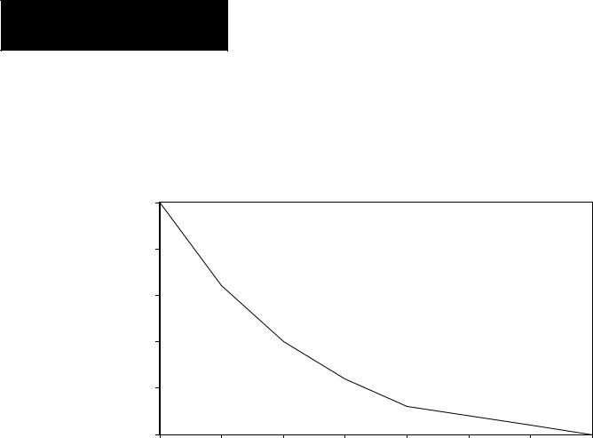
Memory Backup for the SLC 500 Fixed Controller
The curve below illustrates the ability of the memory back±up capacitor to maintain the contents of the RAM in a fixed controller. To back up the memory for a longer period of time, a lithium battery, Catalog Number 1747±BA, is required.
|
30 |
|
|
|
|
|
|
|
|
25 |
|
|
|
|
|
|
|
|
|
|
|
|
Capacitor Memory Back-up Time |
|
||
|
20 |
|
|
|
VS |
|
|
|
|
|
|
|
Temperature |
|
|
|
|
|
|
|
|
|
|
|
|
|
Time |
|
|
|
|
|
|
|
|
(Days) |
15 |
|
|
|
|
|
|
|
|
|
|
|
|
|
|
|
|
|
10 |
|
|
|
|
|
|
|
|
5 |
|
|
|
|
|
|
|
|
25 |
30 |
35 |
40 |
45 |
50 |
55 |
60 |
|
(77°) |
(86°) |
(95°) |
(104°) |
(113°) |
(122°) |
(131°) |
(140°) |
|
|
|
|
|
Temperature °C (°F) |
|
|
|
1±4

Chapter 1
Selecting Your Hardware Components
Configuration Options
The following table provides configuration options for 20, 30, or 40 I/O points.
Catalog |
Line Power |
|
|
I/O Configuration |
High-Speed |
User Power |
||||
|
|
|
|
|
|
|||||
Number |
|
|
Input |
|
|
Output |
Counter |
|||
|
|
|
|
|
|
|||||
|
|
|
|
|
|
|
|
|||
1747-L20A |
|
(12) |
120 Volts AC |
(8) |
AC/DC Relay |
No |
NA |
|||
|
|
|
|
|
|
|
|
|||
1747-L30A |
|
(18) |
120 Volts AC |
(12) |
AC/DC Relay |
No |
NA |
|||
|
|
|
|
|
|
|
|
|||
1747-L40A |
|
(24) |
120 Volts AC |
(16) |
AC/DC Relay |
No |
NA |
|||
|
|
|
|
|
|
|
|
|||
1747-L20B |
|
(12) |
120 Volts AC |
(8) |
AC Triac |
No |
NA |
|||
|
|
|
|
|
|
|
|
|||
1747-L30B |
|
(18) |
120 Volts AC |
(12) |
AC Triac |
No |
NA |
|||
|
|
|
|
|
|
|
|
|||
1747-L40B |
|
(24) |
120 Volts AC |
(16) |
AC Triac |
No |
NA |
|||
|
|
|
|
|
|
|
|
|
||
1747-L20C |
|
(12) |
24 |
Volts DC Sink |
(8) |
AC/DC Relay |
Yes |
24V-200mA |
||
|
|
|
|
|
|
|
|
|
||
1747-L30C |
|
(18) |
24 |
Volts DC Sink |
(12) |
AC/DC Relay |
Yes |
24V-200mA |
||
|
|
|
|
|
|
|
|
|
||
1747-L40C |
|
(24) |
24 |
Volts DC Sink |
(16) |
AC/DC Relay |
Yes |
24V-200mA |
||
|
|
|
|
|
|
|
|
|
||
1747-L20D |
|
(12) |
24 |
Volts DC Sink |
(8) |
AC Triac |
Yes |
24V-200mA |
||
|
|
|
|
|
|
|
|
|
||
1747-L30D |
|
(18) |
24 |
Volts DC Sink |
(12) |
AC Triac |
Yes |
24V-200mA |
||
|
120/240 VAC |
|
|
|
|
|
|
|
||
1747-L20E |
(12) |
24 |
Volts DC Sink |
(8) |
DC Transistor |
Yes |
24V-200mA |
|||
|
Source |
|||||||||
|
|
|
|
|
|
|
||||
|
|
|
|
|
|
|
|
|
||
1747-L40E |
|
(24) |
24 |
Volts DC Sink |
(16) |
DC Transistor |
Yes |
24V-200mA |
||
|
Source |
|||||||||
|
|
|
|
|
|
|
||||
|
|
|
|
|
|
|
|
|
||
1747-L20L |
|
(12) |
24 |
Volts DC |
(8) |
DC Transistor |
Yes |
24V-200mA |
||
|
Source |
|
Sink |
|
||||||
|
|
|
|
|
|
|||||
|
|
|
|
|
|
|
|
|
||
1747-L30L |
|
(18) |
24 |
Volts DC |
(12) |
DC Transistor |
Yes |
24V-200mA |
||
|
Source |
|
Sink |
|
||||||
|
|
|
|
|
|
|||||
|
|
|
|
|
|
|
|
|
||
1747-L40L |
|
(24) |
24 |
Volts DC |
(16) |
DC Transistor |
Yes |
24V-200mA |
||
|
Source |
|
Sink |
|
||||||
|
|
|
|
|
|
|||||
|
|
|
|
|
|
|
|
|||
1747-L20R |
|
(12) |
240 Volts AC |
(8) |
AC/DC Relay |
No |
NA |
|||
|
|
|
|
|
|
|
|
|||
1747-L20P |
|
(12) |
240 Volts AC |
(8) |
AC Triac |
No |
NA |
|||
|
|
|
|
|
|
|
|
|||
1747-L30P |
|
(18) |
240 Volts AC |
(12) |
AC Triac |
No |
NA |
|||
|
|
|
|
|
|
|
|
|||
1747-L40P |
|
(24) |
240 Volts AC |
(16) |
AC Triac |
No |
NA |
|||
|
|
|
|
|
|
|
|
|
||
1747-L20F |
|
(12) |
24 |
Volts DC Sink |
(8) |
AC/DC Relay |
Yes |
NA |
||
|
|
|
|
|
|
|
|
|
||
1747-L40F |
|
(24) |
24 |
Volts DC Sink |
(16) |
AC/DC Relay |
Yes |
NA |
||
|
24 VDC± |
|
|
|
|
|
|
|
|
|
1747-L20G |
(12) |
24 |
Volts DC Sink |
(8) |
DC Transistor |
Yes |
NA |
|||
10% |
||||||||||
Source |
||||||||||
|
|
|
|
|
|
|
||||
|
|
|
|
|
|
|
|
|
||
1747-L20N |
|
(12) |
24 |
Volts DC |
(8) |
DC Transistor |
Yes |
NA |
||
|
Source |
|
Sink |
|
||||||
|
|
|
|
|
|
|||||
|
|
|
|
|
|
|
|
|
|
|
1±5

Chapter 1
Selecting Your Hardware Components
Input Specifications
The following table details the input specifications for SLC 500 Fixed I/O units. See the glossary for a definition of specifications.
Inputs |
|
Specifications |
|
|
|
|
|
|
On-State Voltage |
|
85-132 VAC |
|
|
|
|
|
Frequency |
|
47-63 Hz |
|
|
|
|
|
Off-State Voltage |
|
30 VAC (maximum) |
|
|
|
|
120 VAC |
Inrush Current |
|
0.8A peak |
|
|
|
|
|
Nominal Input Current |
|
12mA at 120 VAC |
|
|
|
|
|
Turn-On Time |
|
35 milliseconds (maximum) |
|
|
|
|
|
Turn-Off Time |
|
45 milliseconds (maximum) |
|
|
|
|
|
Maximum Off-State Current |
|
2mA |
|
|
|
|
|
On-State Voltage |
|
170-265 VAC |
|
|
|
|
|
Frequency |
|
47-63 Hz |
|
|
|
|
|
Off-State Voltage |
|
50 VAC (maximum) |
|
|
|
|
240 VAC |
Inrush Current |
|
1.6A peak |
|
|
|
|
|
Nominal Input Current |
|
12mA at 240 VAC |
|
|
|
|
|
Turn-On Time |
|
35 milliseconds (maximum) |
|
|
|
|
|
Turn-Off Time |
|
45 milliseconds (maximum) |
|
|
|
|
|
Maximum Off-State Current |
|
2mA |
|
|
|
|
|
On-State Voltage |
|
10-30 VDC |
|
|
|
|
|
Off-State Voltage |
|
4 VDC maximum for input 0 (HSC) |
|
|
5 VDC for all others |
|
|
|
|
|
|
|
|
|
|
Nominal Input Current |
|
20mA at 24 VDC (for input 0 only) |
DC Sink & Source |
|
8mA at 24 VDC (all others inputs) |
|
|
|
||
|
|
|
|
|
Turn-On Time |
|
8 milliseconds (maximum) |
|
|
|
|
|
Turn-Off Time |
|
8 milliseconds (maximum) |
|
|
|
|
|
Maximum Off-State Current |
|
1mA |
|
|
|
|
1±6

Chapter 1
Selecting Your Hardware Components
Output Specifications
The following table details the output specifications for SLC 500 Fixed I/O Units.
Outputs |
Specifications |
||
|
|
|
|
|
Output Voltage |
85-265 VAC |
|
|
|
|
|
|
Continuous Current (per output) |
0.5 Amp at +30°C |
|
|
0.25 Amp at +60°C (maximum) |
||
|
|
||
|
|
|
|
|
Minimum Load Current |
10mA |
|
|
|
|
|
Triac |
Turn-On Time |
0.1 milliseconds (maximum) |
|
|
|
||
|
Turn-Off Time |
10 milliseconds (maximum) |
|
|
|
|
|
|
Maximum Off-State Leakage Current |
2mA |
|
|
|
|
|
|
Maximum On-State Voltage Drop |
1.5V @ 0.5 Amps |
|
|
|
|
|
|
Maximum Surge Current |
10 Amps for 25 milliseconds |
|
|
Output Voltage |
10-50 VDC |
|
|
|
|
|
|
Continuous Current (per output) |
0.5 Amp at +30°C |
|
|
0.25 Amp at +60°C (maximum) |
||
|
|
||
|
|
|
|
|
Minimum Load Current |
1mA |
|
Transistor Sink & |
|
|
|
Turn-On Time |
0.1 millisecond (maximum) |
||
Source |
|
|
|
Turn-Off Time |
1 millisecond (maximum) |
||
|
|||
|
|
|
|
|
Maximum Off-State Leakage Current |
1mA |
|
|
|
|
|
|
Maximum On-State Voltage Drop |
1.5V @ 0.5 Amps |
|
|
|
|
|
|
Maximum Surge Current |
3.0 Amps for 25 milliseconds |
|
|
Output Voltage Range |
5-265 VAC, 5-125 VDC |
|
|
|
|
|
|
Continuous Current (per output) |
2.5 Amps (maximum) |
|
|
|
|
|
|
Continuous Current (per group) |
8 Amps (maximum) |
|
Relay |
Maximum Load (per chassis) |
1440 VA |
|
|
|
||
Turn-On Time |
10 milliseconds (maximum) |
||
|
|||
|
|
|
|
|
Turn-Off Time |
10 milliseconds (maximum) |
|
|
|
|
|
|
Maximum Off-State Leakage Current |
0mA |
|
|
|
|
|
|
Minimum Load Current at 5 VDC |
10mA |
|
|
|
|
|
Repeatability is once every 1 second at +30°C. Repeatability is once every 2 seconds at +60°C.
Refer to the wiring diagrams for output groupings on the fixed I/O chassis.
Surge suppression across the output device is recommended to protect relay contacts.
1±7

Chapter 1
Selecting Your Hardware Components
Relay Contact Ratings
Maximum |
|
|
Amperes |
Amperes |
Voltamperes |
||||
|
Volts |
|
Make |
|
Break |
Continuous |
Make |
|
Break |
|
|
|
|
|
|
|
|
|
|
240 |
VAC |
7.5A |
|
|
0.75A |
|
|
|
|
120 |
VAC |
15A |
|
|
1.5A |
2.5A |
1800 VA |
|
180 VA |
|
|
|
|
|
|
|
|
|
|
125 |
VDC |
|
|
0.22A |
1.0A |
|
28 VA |
||
|
|
|
|
|
|
|
|||
24 VDC |
|
|
1.2A |
2.0A |
|
28 VA |
|||
|
|
|
|
|
|
|
|
|
|
To calculate make and break ratings for other load voltages, divide the voltampere rating by the load voltage; for example:
28 VA/48 VDC = 0.583 A
Selecting the 2-Slot Chassis For the 20, 30, and 40 I/O fixed controllers, an optional 2±slot expansion chassis lets you add two additional I/O modules providing even more versatility. The power supply provides backplane power for the modules in the optional expansion chassis.
Refer to chapter 3 for chassis dimensions and chapter 4 for mounting directions.
Selecting Discrete I/O
Modules
Selecting Speciality I/O
Modules
There are three types of I/O modules: input, output, and combination I/O. They are available in a wide variety of densities including 4, 8, 16, and 32 point and can interface to AC, DC, and TTL voltage levels. Output modules are available with solid±state AC, solid±state DC, and relay contact type outputs.
For a complete, up±to±date listing of discrete I/O modules and their specifications, contact your Allen±Bradley sales office for the latest product data entitled Discrete Input and Output Modules, Publication Number 1746±2.35.
Refer to chapter 4 for installation directions.
The SLC 500 family offers specialty I/O modules that enhance your control system. These modules range in function from analog interface to motion control, from communication to high±speed counting.
For a complete, up±to±date listing of specialty I/O modules and their specifications, contact your Allen±Bradley sales office for the latest System Overview entitled SLC 500 Family of Small Programmable Controllers,
Publication Number 1747±2.30, or for a related product data.
Refer to chapter 4 for installation directions.
1±8

Selecting Enclosures
Chapter 1
Selecting Your Hardware Components
The enclosure protects the equipment from atmospheric contamination. Standards established by the National Electrical Manufacturer's Association (NEMA) define enclosure types, based on the degree of protection an enclosure will provide. Use a fan to circulate the air of sealed enclosures that use convection cooling to dissipate heat. Select a NEMA±rated enclosure that suits your application and environment. The enclosure should be equipped with a disconnect device. To calculate the heat dissipation of your controller, see appendix D.
Selecting Operator Interfaces Use an operator interface to program and/or monitor your SLC 500 controller. You can choose from several Allen±Bradley operator interface devices.
Programming with a Hand-Held Terminal (1747-PT1)
Use the Hand±Held Terminal (HHT) to configure the SLC 500 controller, enter/modify a user program, download/upload programs, monitor control operation, and test/troubleshoot. When equipped with a battery (1747±BA), the HHT retains a user program in memory for storage and later use.
The display area accommodates 8 lines x 40 characters. You can display five rungs of a user program. The top row of keys are the menu function keys.
Important: Using the HHT, you can program the SLC 5/01 and 5/02 processors and the SLC 500 fixed controllers. You cannot, however, program the SLC 5/03 processor.
Refer to the Hand±Held Terminal User Manual, Catalog Number 1747±NP002, for information on programming your fixed controller with the HHT.
Programming with Advanced Programming Software (APS) on an IBM
Compatible Computer
The Advanced Programming Software (APS) can be used with an Allen-Bradley T45, T47, or T50 terminal, an IBMr-AT or XT, a Compaqr Portable, Portable II, Deskpro 286, 386/SX, 386, a Tandy 3000HL, Toshiba 3100E, or GATEWAY 2000 models 386DX/25, 386DX/33, 486DX/33, and 486DX2/50 personal computer. Your computer must have:
•640 Kbytes of RAM (extended or expanded memory is recommended, but not required)
•10 Mbyte fixed-disk drive (APS requires a minimum or 2.5 MBytes of free disk space.)
•DOS version 3.1 or higher
1±9

Chapter 1
Selecting Your Hardware Components
Advanced Programming Software, 1747±PA2E
APS, Catalog Number 1747±PA2E, comes on 5±1/4 and 3±1/2 inch disks. You must have DOS installed in your computer. You also must have at least 550 Kbytes of free memory to execute the APS software. Like the Hand±Held Terminal, APS lets you configure the SLC 500 controller, enter/modify a user program, restore/save programs to the SLC 500, monitor controller operation, and test/troubleshoot. You can also:
•create and print ladder diagrams, data tables, instruction cross references, and configurations
•use cut/copy/paste editor
•store multiple programs in the memory of the computer (on the hard disk)
Refer to the Advanced Programming Software User Manual, Catalog Number 1747±NM002, and the Advanced Programming Software Reference
Manual, Catalog Number 1747±NR001, for information on programming your fixed controller with APS.
DH±485 Interface Converter (1747±PIC)
For communication, use an RS±232/DH±485 Interface Converter between the computer and SLC controller. The converter includes a 279.4 mm (11.0 in.) ribbon cable, already attached to the converter, for connection to the computer serial port and a Catalog Number 1746±C10 cable for connection to the controller.
Monitoring with a Data Table Access Module (1747-DTAM-E)
The Data Table Access Module (DTAM) is a plant floor device that lets you access data file information, change operating modes, monitor and clear processor faults, and transfer the user program between RAM and an EEPROM memory module with any SLC 500 family processor. You cannot use it to create new programs.
Important features of DTAM include:
•shorthand addressing, which provides easier access to data files
•display prompts in six, user±selectable languages: English, French, German, Italian, Spanish, and Japanese
•UL listed, CSA Certified
•NEMA type 12 and 13 enclosures
•point±to±point interface to an SLC family processor, or as a network device on a DH±485 network
Refer to the Data Table Access Module (DTAM) User Manual, Catalog Number 1747±ND013, for information on monitoring your fixed controller with the DTAM.
1±10
EEPROM and UVPROM
Memory Modules
Chapter 1
Selecting Your Hardware Components
These optional memory modules provide a non±volatile memory back±up in a convenient modular form. The modules plug into a socket on the controller.
You can store (save) your program in the EEPROM by inserting it into the processor and using either the Hand±Held Terminal or Advanced Programming Software.
Use of the UVPROM provides you with an extra degree of program security because the user program cannot be altered while it is installed in the controller. You can program the UVPROM with commercially available UVPROM programming and erasing equipment. You can use an EEPROM module as a master, or you can use an archived processor file as the source by using the APS PROM translator utility.
Adapter sockets are required when inserting memory modules into commercially available PROM programmer. The memory module fits into the adapter socket and then into a PROM programmer.
ATTENTION: Make sure the adapter is inserted properly or
!damage could result.
The following table lists the types of memory modules that are available for the fixed controller. Also listed are the manufacturer part number for determining compatibility with an external PROM burner.
Description |
Catalog Number |
Manufacturer |
Manufacturer’s Part Number |
|
|
|
|
|
|
|
|
NEC |
uPD28C64 - 250 |
|
|
|
|
|
|
|
|
OKI |
MSM28C64ARS - 20 |
|
1K User Words EEPROM |
1747-M1 |
|
|
|
XICOR |
X28C64BP - 25 |
|||
|
|
|||
|
|
|
|
|
|
|
SEEQ |
PE28C64 - 250 |
|
|
|
|
|
|
|
|
|
X28C256DI - 25 |
|
|
|
XICOR |
|
|
4K User Words EEPROM |
1747-M2 |
X28256DI - 25 |
||
|
||||
|
|
|
|
|
|
|
SEEQ |
DE28C256 - 25 |
|
|
|
|
|
|
1K User Words UVPROM |
1747-M3 |
Fujitsu |
MBM27C64 - 25 |
|
|
|
|
|
|
4K User Words UVPROM |
1747-M4 |
Not compatible with the fixed controller. |
||
|
|
|
|
|
Adaptor Socket |
1747-M5 |
NA |
NA |
|
|
|
|
|
|
1±11
Loading...