


 Loading...
Quick Start
Thermocouple/mV Isolated Input Module
Cat. No. 1746-INT4
Contents
Use this document as a guide to install and wire the 1746-INT4 module. If you need more detailed information, refer to the Thermocouple/mV Isolated Input Module
User Manual, publication 1746-6.16.
For this information |
See page |
Important User Information |
2 |
Prevent Electrostatic Discharge |
3 |
How to Get the Related User Manual |
4 |
Unpack the Module |
4 |
Review Power Requirements |
4 |
Install the Module and Connect the Thermocouples |
5 |
Configure the Software |
12 |
Set Up Channel 0 |
13 |
Program the Transfer of the Configuration Word |
14 |
Write Ladder Logic to Process Input Data |
15 |
Apply Power and Download Your Program |
15 |
Troublshoot the Module |
16 |
Channel Configuration Worksheet |
19 |
For this reference information |
See page |
Specifications |
18 |
Publication 1746-QS002B-EN-P - July 2002

2 Thermocouple/mV Isolated Input Module
Important User Information
Because of the variety of uses for the products described in this publication, those responsible for the application and use of these products must satisfy themselves that all necessary steps have been taken to assure that each application and use meets all performance and safety requirements, including any applicable laws, regulations, codes and standards.
In no event will Rockwell Automation be responsible or liable for indirect or consequential damage resulting from the use or application of these products.
Any illustrations, charts, sample programs, and layout examples shown in this publication are intended solely for purposes of example. Since there are many variables and requirements associated with any particular installation, Rockwell Automation does not assume responsibility or liability (to include intellectual property liability) for actual use based upon the examples shown in this publication.
Allen-BradleyTM publication SGI-1.1, Safety Guidelines for the Application, Installation and Maintenance of Solid-State Control (available from your local Rockwell Automation office), describes some important differences between solid-state equipment and electromechanical devices that should be taken into consideration when applying products such as those described in this publication.
Reproduction of the contents of this copyrighted publication, in whole or part, without written permission of Rockwell Automation, is prohibited.
Throughout this publication, notes may be used to make you aware of safety considerations. The following annotations and their accompanying statements help you to identify a potential hazard, avoid a potential hazard, and recognize the consequences of a potential hazard:
Identifies information about practices or circumstances that can WARNING cause an explosion in a hazardous environment, which may
lead to personal injury or death, property damage, or
!economic loss.
Identifies information about practices or circumstances that can ATTENTION lead to personal injury or death, property damage, or
economic loss.
!
IMPORTANT |
Identifies information that is critical for successful application |
|
and understanding of the product. |
||
|
Publication 1746-QS002B-EN-P - July 2002
Thermocouple/mV Isolated Input Module |
3 |
|
|
ATTENTION |
Environment and Enclosure |
|
This equipment is intended for use in a Pollution Degree 2
!defined in IEC publication 60664-1), at altitudes up to 2000 meters without derating.
This equipment is considered Group 1, Class A industrial equipment according to IEC/CISPR Publication 11. Without appropriate precautions, there may be potential difficulties ensuring electromagnetic compatibility in other environments due to conducted as well as radiated disturbance.
This equipment is supplied as "open type" equipment. It must be mounted within an enclosure that is suitably designed for those specific environmental conditions that will be present and appropriately designed to prevent personal injury resulting from accessibility to live parts. The interior of the enclosure must be accessible only by the use of a tool. Subsequent sections of this publication may contain additional information regarding specific enclosure type ratings that are required to comply with certain product safety certifications.
See NEMA Standards publication 250 and IEC publication 60529, as applicable, for explanations of the degrees of protection provided by different types of enclosure. Also, see the appropriate sections in this publication, as well as the Allen-Bradley publication 1770-4.1 ("Industrial Automation Wiring and
Grounding Guidelines"), for additional installation requirements pertaining to this equipment.industrial environment, in overvoltage Category II applications (as
Prevent Electrostatic Discharge
This equipment is sensitive to electrostatic discharge which can
ATTENTION cause internal damage and affect normal operation. Follow these guidelines when you handle this equipment:
!• touch a grounded object to discharge potential static
•wear an approved grounding wrist strap
•do not touch connectors or pins on component boards
•do not touch circuit components inside the equipment
•if available, use a static-safe workstation
•when not in use, store the equipment in appropriate static-safe packaging
Publication 1746-QS002B-EN-P - July 2002

4 Thermocouple/mV Isolated Input Module
How to Get the Related User Manual
The following table describes the related user manual that is available for this module. To order a copy or to view or download an online version, visit The Automation Bookstore at: www.theautomationbookstore.com
For more detailed information about: |
See this document: |
Publication number: |
Installation, configuration, programming, |
Thermocouple.mV Isolated Input |
1746-6.16 |
diagnostics and troubleshooting |
Module User Manual |
|
|
|
|
Unpack the Module
Unpack the module making sure that the contents include:
•module (catalog number 1746-INT4)
•factory-installed removable terminal block with CJC sensors attached (catalog number 1746-RT32)
•this Quick Start document (publication number 1746-QS002B-EN-P)
If the contents are incomplete, contact your local Rockwell Automation representative for assistance.
Review Power Requirements
Review the power requirements of the modules drawing power from the chassis power supply.
1.The fixed 2-slot chassis supports 2 1746-INT4 modules. If combining an INT4 module with a different type of module, refer to Considerations for a Fixed Controller in Chapter 3 of the user manual.
2.For a modular system, compute the total load on the system power supply using the procedure described in the SLC Installation and Operation Manual for Modular Controllers (publication number 1747-UM011) or the SLC 500 Family System Overview (publication 1747-SO001).
TIP
For more detailed information on these procedures, refer to
Chapter 3 (Installation and Wiring) and Appendix A
(Module Specifications) of the user manual, publication 1746-6.16.
Publication 1746-QS002B-EN-P - July 2002

Thermocouple/mV Isolated Input Module |
5 |
|
|
Install the Module and Connect the Thermocouples
If you insert or remove the module while backplane power is WARNING on, an electrical arc can occur. This could cause an explosion
in hazardous location installations. Be sure that power is
!removed or the area is nonhazardous before proceeding.
Insert/remove the module into/from the I/O chassis (slot 1 in this example procedure).
Important:
Thermocouple inputs are highly susceptible to electrical noise. To minimize interference:
Place processor and I/O chassis in an industrial enclosure.
±Keep signal wires as far from power and load lines as possible.
Use shielded, twisted-pair thermocouple extension wire.
Ground each shield only at one end. Use correct thermocouple polarity. Keep all unshielded leads short. Connect the terminal block GND
(#18) to nearest I/O chassis mtg. bolt with 12 gauge stranded wire.
card guide
Connect thermocouple wires to channels 0-3. We show an example for channel 0. Make sure both cold junction compensation (CJC) devices are securely attached with correct polarity.
module release, |
|
Important: |
|
top and bottom |
Terminal Block |
||
Ground all thermocouple shields |
|||
|
|||
+ |
|
to earth ground at I/O chassis |
|
CHL 0+ |
with 3/8º braid wire. See User |
||
|
|||
± |
|
Manual, figure 3.2. |
|
CJC A |
CHL 0± |
|
|
Device |
|
||
|
CHL 1+ |
|
|
|
CHL 1± |
|
|
|
Thermocouple Wire |
||
To install your module into the chassis:
1. Turn off the chassis power supply.
If you insert or remove the module while backplane power is WARNING on, an electrical arc can occur. This could cause an explosion
in hazardous location installations. Be sure that power is
!removed or the area is nonhazardous before proceeding.
Publication 1746-QS002B-EN-P - July 2002
6Thermocouple/mV Isolated Input Module
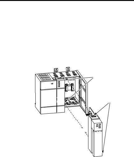
2.Align the circuit board of the thermocouple module with the card guides located at the top and bottom of the chassis.
3.Slide the module into the chassis until both top and bottom retaining clips are secured. Apply firm even pressure on the module to attach it to its backplane connector. Never force the module into the slot.
4.Cover unused slots with the card slot filler, catalog number 1746–N2.
5.To remove, press the releases at the top and bottom of the module, and slide the module out of the chassis slot.
card guides
top and bottom releases
retaining clips
Publication 1746-QS002B-EN-P - July 2002
Loading...