


 Loading...
User Manual
Medium Voltage Controllers, 200/400A Two-High Cabinet,
Standard and Arc-Resistant Enclosure
Publication 1500-UM055G-EN-P

Important User Information
Solid-state equipment has operational characteristics differing from those of electromechanical equipment. Safety Guidelines for the Application, Installation and Maintenance of Solid State Controls (publication SGI-1.1 available from your local Rockwell Automation sales office or online at http://www.rockwellautomation.com/literature/) describes some important differences between solid-state equipment and hard-wired electromechanical devices. Because of this difference, and also because of the wide variety of uses for solid-state equipment, all persons responsible for applying this equipment must satisfy themselves that each intended application of this equipment is acceptable.
In no event will Rockwell Automation, Inc. be responsible or liable for indirect or consequential damages resulting from the use or application of this equipment.
The examples and diagrams in this manual are included solely for illustrative purposes. Because of the many variables and requirements associated with any particular installation, Rockwell Automation, Inc. cannot assume responsibility or liability for actual use based on the examples and diagrams.
No patent liability is assumed by Rockwell Automation, Inc. with respect to use of information, circuits, equipment, or software described in this manual.
Reproduction of the contents of this manual, in whole or in part, without written permission of Rockwell Automation, Inc., is prohibited.
Throughout this manual, when necessary, we use notes to make you aware of safety considerations.
WARNING: Identifies information about practices or circumstances that can cause an explosion in a hazardous environment, which may lead to personal injury or death, property damage, or economic loss.
ATTENTION: Identifies information about practices or circumstances that can lead to personal injury or death, property damage, or economic loss. Attentions help you identify a hazard, avoid a hazard, and recognize the consequence.
SHOCK HAZARD: Labels may be on or inside the equipment, for example, a drive or motor, to alert people that dangerous voltage may be present.
BURN HAZARD: Labels may be on or inside the equipment, for example, a drive or motor, to alert people that surfaces may reach dangerous temperatures.
ARC FLASH HAZARD: Labels may be on or inside the equipment, for example, a motor control center, to alert people to potential Arc Flash. Arc Flash will cause severe injury or death. Wear proper Personal Protective Equipment (PPE). Follow ALL Regulatory requirements for safe work practices and for Personal Protective Equipment (PPE).
IMPORTANT Identifies information that is critical for successful application and understanding of the product.
Allen-Bradley, Rockwell Software, Rockwell Automation, and TechConnect are trademarks of Rockwell Automation, Inc.
Trademarks not belonging to Rockwell Automation are property of their respective companies.

Summary of Changes
New and Updated
Information
This manual contains new and updated information.
This table contains the changes made to this revision.
Topic |
Page |
|
|
Converted the document to FrameMaker |
Throughout |
|
|
Inserted Arc Flash warning |
ii |
|
|
Added Isolation Blade Switch Adjustment section |
59 |
|
|
Rockwell Automation Publication 1500-UM055G-EN-P - May 2013 |
iii |

Summary of Changes
Notes:
iv |
Rockwell Automation Publication 1500-UM055G-EN-P - May 2013 |

|
|
Table of Contents |
|
Chapter 1 |
|
General Information |
Document Scope. . . . . . . . . . . . . . . . . . . . . . . . . . . . . . . . . . . |
. . . . . . . . . . . . . . . . 1 |
|
Starter Identification . . . . . . . . . . . . . . . . . . . . . . . . . . . . . . . . |
. . . . . . . . . . . . . . . 2 |
|
Prepared Space. . . . . . . . . . . . . . . . . . . . . . . . . . . . . . . . . . . . . . |
. . . . . . . . . . . . . . . 3 |
|
Series Number . . . . . . . . . . . . . . . . . . . . . . . . . . . . . . . . . . |
. . . . . . . . . . . . . . . 3 |
|
Motor Data . . . . . . . . . . . . . . . . . . . . . . . . . . . . . . . . . . . . . |
. . . . . . . . . . . . . . . 3 |
|
Starter Features . . . . . . . . . . . . . . . . . . . . . . . . . . . . . . . . . |
. . . . . . . . . . . . . . . 3 |
|
Recommended Torque Values . . . . . . . . . . . . . . . . . . . . . . . |
. . . . . . . . . . . . . . . 3 |
|
Chapter 2 |
|
Installation – Standard Enclosure |
Door Opening Procedure . . . . . . . . . . . . . . . . . . . . . . . . . . . . |
. . . . . . . . . . . . . . . 5 |
|
Opening the Low Voltage Doors. . . . . . . . . . . . . . . . . . |
. . . . . . . . . . . . . . . 5 |
|
Opening the Medium Voltage Doors. . . . . . . . . . . . . . |
. . . . . . . . . . . . . . . 6 |
|
Anchoring. . . . . . . . . . . . . . . . . . . . . . . . . . . . . . . . . . . . . . . . . . |
. . . . . . . . . . . . . . . 7 |
|
Joining Sections. . . . . . . . . . . . . . . . . . . . . . . . . . . . . . . . . . . . . |
. . . . . . . . . . . . . . . 8 |
|
Access to the Power Bus . . . . . . . . . . . . . . . . . . . . . . . . . . . . . |
. . . . . . . . . . . . . . . 9 |
|
Rear Access . . . . . . . . . . . . . . . . . . . . . . . . . . . . . . . . . . . . . |
. . . . . . . . . . . . . . . 9 |
|
Side Access. . . . . . . . . . . . . . . . . . . . . . . . . . . . . . . . . . . . . . |
. . . . . . . . . . . . . 11 |
|
Front Access– Access to Power Bus . . . . . . . . . . . . . . . |
. . . . . . . . . . . . . 11 |
|
Front Access – Bottom Exiting Load Cables . . . . . . . |
. . . . . . . . . . . . . 16 |
|
Load Cable Connections . . . . . . . . . . . . . . . . . . . . . . . . . . . . |
. . . . . . . . . . . . . 17 |
|
Top Exiting Load Cables. . . . . . . . . . . . . . . . . . . . . . . . . |
. . . . . . . . . . . . . 19 |
|
Bottom Exiting Load Cables . . . . . . . . . . . . . . . . . . . . . |
. . . . . . . . . . . . . 20 |
Installation–Arc-ResistantEnclosure (ArcShield)
Chapter 3
Door Opening Procedure . . . . . . . . . . . . . . . . . . . . . . . . . . . . . . . . . . . . . . . . . 21 Opening the Low Voltage Doors. . . . . . . . . . . . . . . . . . . . . . . . . . . . . . . 21 Opening the Medium Voltage Doors. . . . . . . . . . . . . . . . . . . . . . . . . . . 22 Anchoring. . . . . . . . . . . . . . . . . . . . . . . . . . . . . . . . . . . . . . . . . . . . . . . . . . . . . . . 23 Joining Sections. . . . . . . . . . . . . . . . . . . . . . . . . . . . . . . . . . . . . . . . . . . . . . . . . . 25 Access to the Power Bus . . . . . . . . . . . . . . . . . . . . . . . . . . . . . . . . . . . . . . . . . . 26 Rear Access . . . . . . . . . . . . . . . . . . . . . . . . . . . . . . . . . . . . . . . . . . . . . . . . . . 26
Side Access. . . . . . . . . . . . . . . . . . . . . . . . . . . . . . . . . . . . . . . . . . . . . . . . . . . 26
Front Access – Access to Power Bus. . . . . . . . . . . . . . . . . . . . . . . . . . . . 28 Front Access – Bottom Exiting Load Cables . . . . . . . . . . . . . . . . . . . . 31
Load Cable Connections . . . . . . . . . . . . . . . . . . . . . . . . . . . . . . . . . . . . . . . . . 32
Top Exiting Load Cables. . . . . . . . . . . . . . . . . . . . . . . . . . . . . . . . . . . . . . 33 Bottom Exiting Load Cables . . . . . . . . . . . . . . . . . . . . . . . . . . . . . . . . . . 34
|
Chapter 4 |
|
Common Installation |
Bus Splicing . . . . . . . . . . . . . . . . . . . . . . . . . . . . . . . . . . . . . . . . . . . . . . . . . . . . . |
35 |
|
Power Bus . . . . . . . . . . . . . . . . . . . . . . . . . . . . . . . . . . . . . . . . . . . . . . . . . . . |
35 |
|
Insulated Power Bus Splicing . . . . . . . . . . . . . . . . . . . . . . . . . . . . . . . . . . |
36 |
|
Ground Bus. . . . . . . . . . . . . . . . . . . . . . . . . . . . . . . . . . . . . . . . . . . . . . . . . . |
37 |
Rockwell Automation Publication 1500-UM055G-EN-P - May 2013 |
v |

Table of Contents |
|
|
|
Incoming Line Cable Connections. . . . . . . . . . . . . . . . . . . . . . . . . . . . . . . . . |
37 |
|
Installation of Current Transformer Barrier . . . . . . . . . . . . . . . . . . . . . . . . |
39 |
|
Hi-Pot and Megger Test . . . . . . . . . . . . . . . . . . . . . . . . . . . . . . . . . . . . . . . . . . |
39 |
|
Start-up Procedure . . . . . . . . . . . . . . . . . . . . . . . . . . . . . . . . . . . . . . . . . . . . . . . |
40 |
|
Contactor Inspection . . . . . . . . . . . . . . . . . . . . . . . . . . . . . . . . . . . . . . . . . |
40 |
|
Preliminary Checks . . . . . . . . . . . . . . . . . . . . . . . . . . . . . . . . . . . . . . . . . . . |
40 |
|
Testing Contactor Operation. . . . . . . . . . . . . . . . . . . . . . . . . . . . . . . . . . |
41 |
|
Typical Wiring Diagrams . . . . . . . . . . . . . . . . . . . . . . . . . . . . . . . . . . . . . . . . . |
42 |
|
Chapter 5 |
|
Maintenance |
Tool Requirements . . . . . . . . . . . . . . . . . . . . . . . . . . . . . . . . . . . . . . . . . . . . . . . |
45 |
|
Recommended Torque Values. . . . . . . . . . . . . . . . . . . . . . . . . . . . . . . . . . . . . |
45 |
|
Door Interlock Circumvention . . . . . . . . . . . . . . . . . . . . . . . . . . . . . . . . . . . . |
46 |
|
Power Lock-out Procedure . . . . . . . . . . . . . . . . . . . . . . . . . . . . . . . . . . . . . . . . |
47 |
|
Fuse Removal and Replacement . . . . . . . . . . . . . . . . . . . . . . . . . . . . . . . . . . . |
50 |
|
Bolt-on Fuse Removal/Installation . . . . . . . . . . . . . . . . . . . . . . . . . . . . . |
51 |
|
Clip-on Fuse Removal/Installation. . . . . . . . . . . . . . . . . . . . . . . . . . . . . |
51 |
|
Contactor Maintenance. . . . . . . . . . . . . . . . . . . . . . . . . . . . . . . . . . . . . . . . . . . |
52 |
|
Removing the Contactor. . . . . . . . . . . . . . . . . . . . . . . . . . . . . . . . . . . . . . . . . . |
52 |
|
Contactor Interlock Rod Adjustment . . . . . . . . . . . . . . . . . . . . . . . . . . . . . . |
54 |
|
To Reduce the Gap Distance . . . . . . . . . . . . . . . . . . . . . . . . . . . . . . . . . . |
55 |
|
To Increase the Gap Distance. . . . . . . . . . . . . . . . . . . . . . . . . . . . . . . . . . |
55 |
|
Isolation Switch Mechanism Inspection and Lubrication . . . . . . . . . . . . |
57 |
|
Isolation Blade Switch Adjustment . . . . . . . . . . . . . . . . . . . . . . . . . . . . . . . . |
59 |
|
Isolation Switch Mechanism Grounding Adjustment. . . . . . . . . . . . . . . . |
62 |
|
Auxiliary Contacts Inspection and Replacement . . . . . . . . . . . . . . . . . . . . |
63 |
|
Isolation Switch Auxiliary Contacts. . . . . . . . . . . . . . . . . . . . . . . . . . . . . . . . |
64 |
|
Adjusting the Normally Open (ISa) Contacts . . . . . . . . . . . . . . . . . . . |
64 |
|
Adjusting the Normally Closed (ISb) Contacts. . . . . . . . . . . . . . . . . . |
65 |
|
Adjusting the Change-of-State Point . . . . . . . . . . . . . . . . . . . . . . . . . . . |
66 |
|
Emergency Circumvention Procedure for Power Cell Entry. . . . . . . . . . |
66 |
|
Installing Z-clip with Isolation Switch Handle in the |
|
|
OFF Position. . . . . . . . . . . . . . . . . . . . . . . . . . . . . . . . . . . . . . . . . . . . . . . . . |
68 |
|
Installing Z-clip with Isolation Switch Handle in the |
|
|
ON Position . . . . . . . . . . . . . . . . . . . . . . . . . . . . . . . . . . . . . . . . . . . . . . . . . |
68 |
|
Chapter 6 |
|
Spare Parts |
Bulletin 1512 and 1512BT Units Parts List. . . . . . . . . . . . . . . . . . . . . . . . . |
69 |
|
Appendix A |
|
ArcShield Unit Information |
Overview . . . . . . . . . . . . . . . . . . . . . . . . . . . . . . . . . . . . . . . . . . . . . . . . . . . . . . . . |
71 |
|
ArcShield Design . . . . . . . . . . . . . . . . . . . . . . . . . . . . . . . . . . . . . . . . . . . . . . . . . |
71 |
|
Exhaust Systems: Chimney or Plenum Option . . . . . . . . . . . . . . . . . . . . . . |
72 |
|
Plenum Information . . . . . . . . . . . . . . . . . . . . . . . . . . . . . . . . . . . . . . . . . . |
72 |
|
Plenum Exhaust Considerations . . . . . . . . . . . . . . . . . . . . . . . . . . . . . . . |
73 |
|
Additional Notes . . . . . . . . . . . . . . . . . . . . . . . . . . . . . . . . . . . . . . . . . . . . . |
75 |
vi |
Rockwell Automation Publication 1500-UM055G-EN-P - May 2013 |

Table of Contents
ArcShield Plenum Installation
Instructions
ArcShield Chimney Installation
Instructions
Chimney Information . . . . . . . . . . . . . . . . . . . . . . . . . . . . . . . . . . . . . . . . 76
Chimney Exhaust Considerations . . . . . . . . . . . . . . . . . . . . . . . . . . . . . 76
Appendix B
Recommended Torque Values . . . . . . . . . . . . . . . . . . . . . . . . . . . . . . . . . . . . 77
Plenum Bracing . . . . . . . . . . . . . . . . . . . . . . . . . . . . . . . . . . . . . . . . . . . . . . . . . . 77
General Plenum Layout for ArcShield Line-up . . . . . . . . . . . . . . . . . . . . . 78 STEP 1 – Mounting a Single Plenum . . . . . . . . . . . . . . . . . . . . . . . . . . . . . . 79
Cabinet Preparation . . . . . . . . . . . . . . . . . . . . . . . . . . . . . . . . . . . . . . . . . . 80
Plenum Placement on Structure . . . . . . . . . . . . . . . . . . . . . . . . . . . . . . . 80 STEP 2 – Alignment of “Side-by-Side” Plenums . . . . . . . . . . . . . . . . . . . . 81
STEP 3 – Sequence of Final Assembly . . . . . . . . . . . . . . . . . . . . . . . . . . . . . 82
STEP 4 – Closing the Front of the Plenum Sections . . . . . . . . . . . . . . . . 83 STEP 5 – Extension and Elbow Assembly . . . . . . . . . . . . . . . . . . . . . . . . . . 83
STEP 6 – Mounting Extension/Elbow to Plenum “Line-up”. . . . . . . . . 84 STEP 7 – Additional Mounting Support. . . . . . . . . . . . . . . . . . . . . . . . . . . 86
Appendix C
Recommended Torque Values . . . . . . . . . . . . . . . . . . . . . . . . . . . . . . . . . . . . 87 General Plenum Layout for ArcShield Line-up . . . . . . . . . . . . . . . . . . . . . 88 Cabinet Preparation . . . . . . . . . . . . . . . . . . . . . . . . . . . . . . . . . . . . . . . . . . 89 Chimney Placement on Structure. . . . . . . . . . . . . . . . . . . . . . . . . . . . . . 90
Rockwell Automation Publication 1500-UM055G-EN-P - May 2013 |
vii |

Table of Contents
Notes:
viii |
Rockwell Automation Publication 1500-UM055G-EN-P - May 2013 |

Chapter 1
General Information
Document Scope
This User Manual pertains to the Rockwell Automation Bulletin 1512B medium voltage controller. The Bulletin 1512B structure includes provisions for two complete MV controller units.
The installation section provides instructions for both the standard enclosure type and Rockwell Automation arc resistant type (ArcShield).
The product Bulletin numbers covered by this document are:
• |
1512B |
200/400 A |
FVNR controller |
• |
1512BT |
200/400 A |
Transformer Feeder |
• |
1512BP |
200/400 A |
Prepared Space(1) |
IMPORTANT This document is to be used for all Bulletin 1512B unit types, including arc resistant (ArcShield™) units. Important information specifically for ArcShield units can be found in Appendix A, Appendix B and Appendix C.
ATTENTION: Users must refer to the information in Appendix A, Appendix B and Appendix C to correctly install and maintain ArcShield arc resistant units. Failure to do so may negate the arc resistant benefits provided by ArcShield, exposing personnel to risk of serious injury or death.
This document may also be used as a reference guide for the following Bulletin numbers:
• |
1512DM |
200/400 A VFD Input Contactor Units |
|
• |
1512DO |
200/400 A |
VFD Output Contactor units |
• |
1512M |
200/400 A |
VFD Output Bypass Starter |
• |
1562E |
200/400 A |
MV SMC Flex Solid-State |
(up to 4800V) Reduced Voltage Starter
•1591B Incoming Line Unit
•1592BF Fused Load Break Switch for Feeders
•1592BP Fused Load Break Switch for Feeders, prepared space
(1) Not available on arc-resistant designs.
Rockwell Automation Publication 1500-UM055G-EN-P - May 2013 |
1 |
Chapter 1 General Information
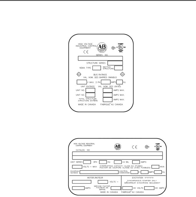
Starter Identification
A structure nameplate is attached to the right-side flange of the structure (see Figure 1). Refer to the nameplate for information such as series number, section number, NEMA enclosure type, unit ratings and bus ratings.
Figure 1 - Typical Structure Nameplate
A unit nameplate is also found in the low voltage compartment with specific unit motor application information (see Figure 2).
Figure 2 - Typical Unit Nameplate
Refer to these nameplates whenever you contact Rockwell Automation for assistance. Be prepared to provide such information as series number, structure series, unit series, diagram schematic and catalog number.
2 |
Rockwell Automation Publication 1500-UM055G-EN-P - May 2013 |
General Information |
Chapter 1 |
|
|
Prepared Space
Recommended Torque
Values
When ordering a starter kit to complete a prepared space(2), provide the following information to ensure the proper components are supplied.
Series Number
Provide the series number from the structure with the prepared space. The number is stamped on a nameplate on the right-hand flange of the starter (see Figure 1). The series number is also available from the dimension drawings for the starter.
Motor Data
Provide the following motor data:
•Locked rotor current
•Full load current
•Maximum locked rotor time
•Acceleration time
•Motor service factor
•Motor horsepower
Starter Features
Provide information regarding any special features required for the starter kit. Indicate if these features are different from the motor control features in the existing, complete power cell.
When reinstalling components or when reassembling the cabinet, tighten the following bolt sizes to the specified torque values:
Table 1 - Hardware Torque Values
1/4 in. hardware |
8 N•m (6 lb•ft) |
|
|
5/16 in. hardware |
15 N•m (12 lb•ft) |
|
|
3/8 in. hardware |
27 N•m (20 lb•ft) |
|
|
1/2 in. hardware |
65 N•m (48 lb•ft) |
|
|
(2) Not available on arc resistant cabinets.
Rockwell Automation Publication 1500-UM055G-EN-P - May 2013 |
3 |

Chapter 1 General Information
Notes:
4 |
Rockwell Automation Publication 1500-UM055G-EN-P - May 2013 |

Chapter 2
Installation – Standard Enclosure
|
|
IMPORTANT For information on the installation site preparation, see General Handling |
||||||||||
|
|
|
|
Procedures for MV Products, Publication MV-QS050_-EN-P. |
||||||||
|
|
|
|
|
|
|
|
|
|
|
|
|
|
|
|
|
|
|
|
|
|
|
|
|
|
|
|
|
|
ATTENTION: Use suitable personal protective equipment (PPE) per local codes |
||||||||
|
|
|
|
or regulations. Failure to do so may result in severe burns, injury or death. |
||||||||
Door Opening Procedure |
|
|
|
|
|
|
|
|
|
|
|
|
|
Opening the Low Voltage Doors |
|||||||||||
|
|
Low voltage doors are identified as LV in Figure 3. |
||||||||||
|
|
1. To access the compartments for standard cabinets – use a flat-head |
||||||||||
|
|
screwdriver and turn both of the 1/4-turn fasteners at least 90° in a |
||||||||||
|
|
counterclockwise direction. |
|
|
|
|
||||||
|
|
2. The door is now released and will swing open. |
||||||||||
|
|
3. Reverse the procedure to secure the doors. |
||||||||||
|
|
Figure 3 - Access to Low Voltage Compartments |
||||||||||
|
|
|
|
|
|
|
|
|
|
|
|
|
|
|
|
|
|
|
|
. |
|
|
. |
|
|
|
1/4-turn fasteners for |
|
|
MV |
|
|
|
|||||
|
|
|
|
|
|
|||||||
|
Upper Low Voltage Door |
|
|
|
|
|
|
|
|
|
||
|
|
|
|
|
|
|
|
|
|
. |
|
|
|
|
|
|
|
|
|
|
|
|
|
|
|
|
|
|
|
|
|
|
. |
|
|
. |
|
|
|
1/4-turn fasteners for |
|
|
MV |
|
|
|
|||||
|
Lower Low Voltage Door |
|
|
|
|
|
|
|
||||
|
|
|
|
|
|
|
|
|
|
|
|
|
|
|
|
|
|
|
|
. |
|
|
. |
|
|
|
|
|
|
|
|
|
|
|
|
|
|
|
Rockwell Automation Publication 1500-UM055G-EN-P - May 2013 |
5 |

Chapter 2 Installation – Standard Enclosure
Opening the Medium Voltage Doors
ATTENTION: Medium voltage components are located behind the swing-out low voltage panel (standard cabinets only). Complete the Power Lock-out procedure (refer to Power Lock-out Procedure on page 47 of Chapter 5) before attempting to open the swing-out low voltage panel. Failure to do so may result in severe burns, injury or death.
ATTENTION: Complete the Power Lock-out procedure (refer to Power Lock-out Procedure on page 47 of Chapter 5) before beginning any service procedures to the unit. Failure to do so may result in severe burns, injury or death.
Medium voltage doors are identified as MV in Figure 4.
Figure 4 - Access to Medium Voltage Compartments
Isolation
Switch
Handles
. .
LV MV
.
Door Locking Bolts for Upper Medium Voltage Door
LV MV
Door Locking Bolts for Upper Medium Voltage Door
.
IMPORTANT Each medium voltage door has its own isolation switch handle and interlocking safeguards. Upper and lower power cells are separated by an isolation barrier.
Refer to Access to the Power Bus on page 9 for the procedure to open the swingout low voltage panel behind the low voltage door (for standard cabinet only).
1.Electrically open the contactor by pressing the STOP button on the starter or at the remote control location.
2.Move the isolation switch handle to the OFF position.
3.Unscrew the door locking bolts for medium voltage door.
6 |
Rockwell Automation Publication 1500-UM055G-EN-P - May 2013 |

Anchoring
Installation – Standard Enclosure |
Chapter 2 |
4.The door is now released and will swing open.
5.Reverse the procedure to close the door.
IMPORTANT Ensure that the swing-out low voltage panel is in its original position before attempting to close the MV door. When closing the medium voltage door, ensure all door locking bolts on the right side of the MV door are in place and tightened until the door is flush with the flange. Do not overtighten the bolts. If the door is not securely fastened, it will not be possible to move the isolation switch handle to the ON position.
ATTENTION: Complete the Power Lock-out procedure (refer to Power Lock-out Procedure on page 47 of Chapter 5) before beginning any service procedures to the unit. Failure to do so may result in severe burns, injury or death.
Place the controller in the desired installation location. Use 12 mm (1/2 in. [M12]) floor mounting bolts to securely fasten the controller to the mounting surface. See Figure 5 as an example of the location of the mounting holes in the cabinet.
TIP |
Refer to Dimension Drawing provided with order documentation for additional |
|
details related to cabinet floor plan. |
IMPORTANT Pre-determined cabinets have been designed for Uniform Building Code (UBC) seismic zone 1, 2A, 2B, 3 and 4, and IBC (International Building Code) seismic activity without overturning or lateral movement, provided they are securely mounted according to UBC, IBC and local building codes. This can include concrete pad design, steel floor design and the sizing of cabinet anchors. Concrete floor cutouts must not be adjacent to floor anchor bolts and must be sized to seismic load. Consult factory if floor mounting must be reviewed by an accredited engineer. Many jurisdictions require an engineer from the local area to review the design. Seismic qualification does not indicate that the equipment will function properly after a seismic event.
Rockwell Automation Publication 1500-UM055G-EN-P - May 2013 |
7 |
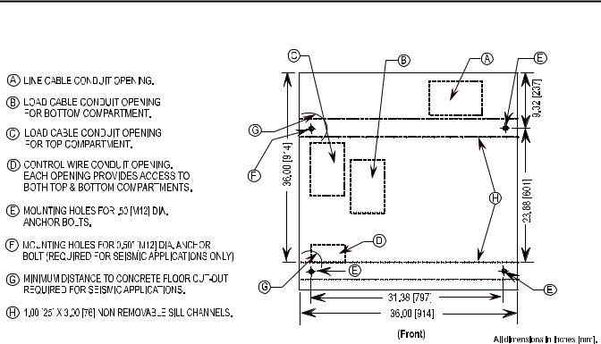
Chapter 2 Installation – Standard Enclosure
Figure 5 - Cabinet Floor Plan
Joining Sections
NOTES FOR SEISMIC APPLICATIONS
•For installations on concrete – the minimum depth and radius of concrete supporting the cabinet anchors is dependent on seismic loads. Refer to important information above.
•For installations on a metal structure – the metal plate depth and cabinet anchoring method is dependent on seismic loads.
TIP |
Joining hardware can be found in a package mounted on the front of the |
|
shipping skid. Refer to publication MV-QS050_-EN-P for level floor surface |
|
requirements. |
1.Position the left side of the section on a level surface and secure the section in place with 12 mm (1/2 in. [M12]) floor mounting bolts (refer
to Anchoring on page 7).
2.When joining NEMA Type 12, apply a continuous 3 mm (1/8 in.) wide bead of silicon sealer around the perimeter of one section.
3.Remove the side bus access covers if applicable.
4.Position the right section against the left section. Ensure that the surface is level.
8 |
Rockwell Automation Publication 1500-UM055G-EN-P - May 2013 |

0.219 Pilot
Holes (5x)
0.281 Pilot
Holes (5x)
Fr o nt
Installation – Standard Enclosure |
Chapter 2 |
5.Secure the sections together using the 1/4-20 self-tapping screws. Thread the screw through the 7 mm (0.281 in.) clearance hole to the corresponding 6 mm (0.219 in.) pilot hole. To access the front clearance holes of the left-side cabinet, open the medium voltage doors. To access the rear clearance holes remove the rear covers of the starter. If rear access is not available, refer to Front Access– Access to Power Bus on page 11.
6.Secure the right section to the floor using 12 mm (1/2 in. [M12]) floor mounting bolts (refer to Anchoring on page 7).
Figure 6 - Joining Sections
Side Bus
Access Cover
0.281 Pilot
Holes (5x)
0.219 Pilot
Holes (3x)
t n ro F
Access to the Power Bus
ATTENTION: This procedure requires contact with medium voltage components. To avoid shock hazards, lock out incoming power before working on the equipment (refer to Power Lock-out Procedure on page 47 of Chapter 5). Verify with a hot stick or appropriate voltage measuring device that all circuits are voltage free. Failure to do so may result in severe burns, injury or death.
Rear Access
1.Remove the hardware securing the center rear bus access cover (see Figure 7).
2.Remove the center rear bus access cover.
Rockwell Automation Publication 1500-UM055G-EN-P - May 2013 |
9 |
Chapter 2 Installation – Standard Enclosure
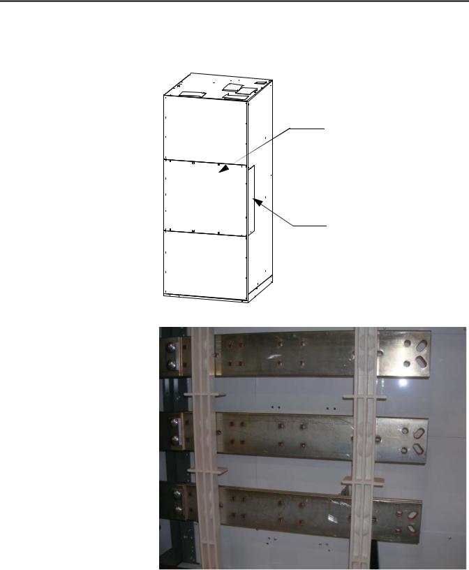
3.Once the rear bus cover is removed, you will see the three power bus bars and the ground bus bar (see Figure 8).
Figure 7 - Access to Power Bus from Side and Rear of Cabinet
Center Rear Bus
Access Cover
Side Bus
Access Cover
Figure 8 - Bus Bars from Back Access
10 |
Rockwell Automation Publication 1500-UM055G-EN-P - May 2013 |
Installation – Standard Enclosure |
Chapter 2 |
|
|
Side Access
A side bus access cover is located on each side of the controller.
1.Remove the hardware from the appropriate side bus access cover (see Figure 7).
2.Remove the side bus access cover.
3.Once the side bus access cover is removed, you will see the three power bus bars and the ground bus (see Figure 9).
Figure 9 - Side Bus Access Cover Removed
Front Access– Access to Power Bus
ATTENTION: To avoid shock hazards, lock out incoming power (refer to Power Lock-out Procedure on page 47 of Chapter 5) before working on the equipment. Verify with a hot stick or appropriate voltage measuring device that all circuits are voltage free. Failure to do so may result in severe burns, injury or death.
1.Complete the Power Lock-out Procedure (refer to Power Lock-out Procedure on page 47 of Chapter 5) for both medium voltage power cells and the power bus.
2.Open the doors and remove the hinge pins.
Rockwell Automation Publication 1500-UM055G-EN-P - May 2013 |
11 |

Chapter 2 Installation – Standard Enclosure
3.Open the low voltage cell doors (refer to Opening the Low Voltage Doors on page 5).
4.Disconnect the control wiring harness from the wire plug at the lower left side of the contactor.
5.Remove the two self-tapping screws from the center vertical channel (see Figure 10).
6.Pull on the center vertical channel to swing out the low voltage panel.
Figure 10 - Center Vertical Channel
Remove self-tapping screws from center vertical channel
Control Wiring Harness
12 |
Rockwell Automation Publication 1500-UM055G-EN-P - May 2013 |
Installation – Standard Enclosure |
Chapter 2 |
|
|
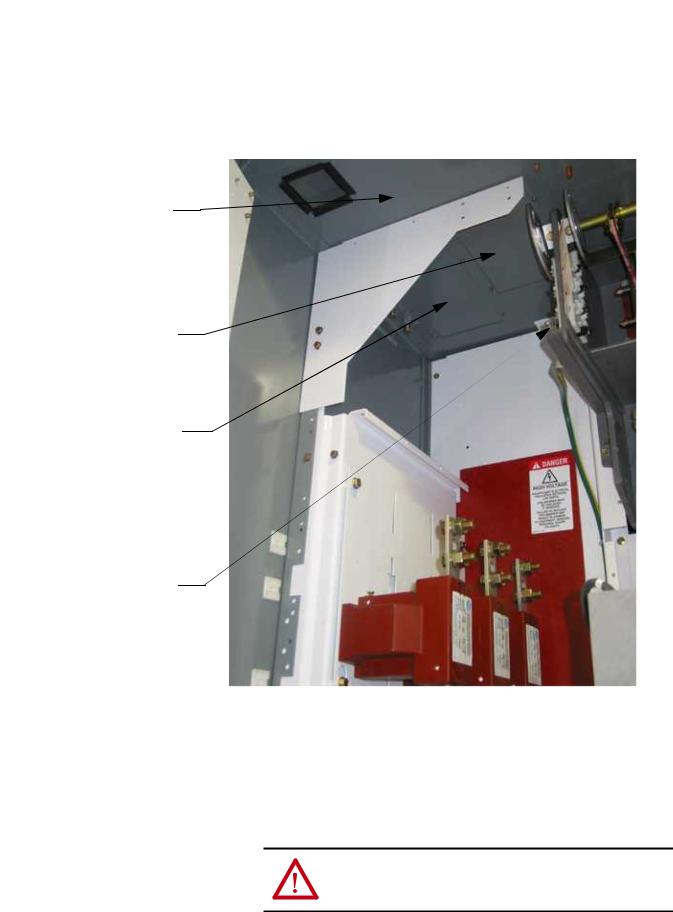
7.Remove each glass-polyester barrier located in front of the current transformers (see Figure 11).
Figure 11 - Removing Glass-polyester Barrier
Current Transformers
Remove self-tapping screws from barrier assembly
Glass-polyester barrier
8.Remove the retaining screw from the cable duct barrier and remove the barrier (see Figure 12).
9.Remove the two retaining screws from the cable duct boot and remove the boot (see Figure 12).
Rockwell Automation Publication 1500-UM055G-EN-P - May 2013 |
13 |

Chapter 2 Installation – Standard Enclosure
Current Transformers
CT Mounting Plate
Loosen Retaining Screws
Cable Duct Boot
Remove Retaining Screws
Cable Duct Barrier
Remove four selftapping screws from each Bus Access Cover
Figure 12 - Removing Cable Duct Boot and Barrier
10.To access the left side of the power bus, locate the two bus access covers at the rear, left side of the power cell. Remove the four self-tapping screws from each cover and remove the covers (see Figure 13).
Figure 13 - Removing Bus Access Covers
14 |
Rockwell Automation Publication 1500-UM055G-EN-P - May 2013 |

Installation – Standard Enclosure |
Chapter 2 |
|
|
11.If access to the right side of the power bus is required, remove the vacuum contactor from the upper power cell (refer to Removing the Contactor on page 52 of Chapter 5).
12.Remove the power fuses from the isolation switch.
13.Remove the interphase barriers from the trailer fuse block by raising them vertically up and out of the mounting slots (see Figure 14).
14.Use a 9/16-in. socket to remove the contactor bus bars from the isolation switch trainer fuse block.
Figure 14 - Contactor Bus Bars (Trailer Fuse Block for Clip-on Fuses Shown)
Trailer Fuse Block
Mounting Bolts 


Contactor Bus Bars
15.Disconnect the secondary control wiring from the control power transformer (CPT) and remove the CPT mounting plate. Leave the CPT attached to the plate.
ATTENTION: The CPT is heavy and assistance may be required to safely remove and transport the unit. Use caution when removing the CPT. Failure to do so may result in personal injury and/or damage to the equipment.
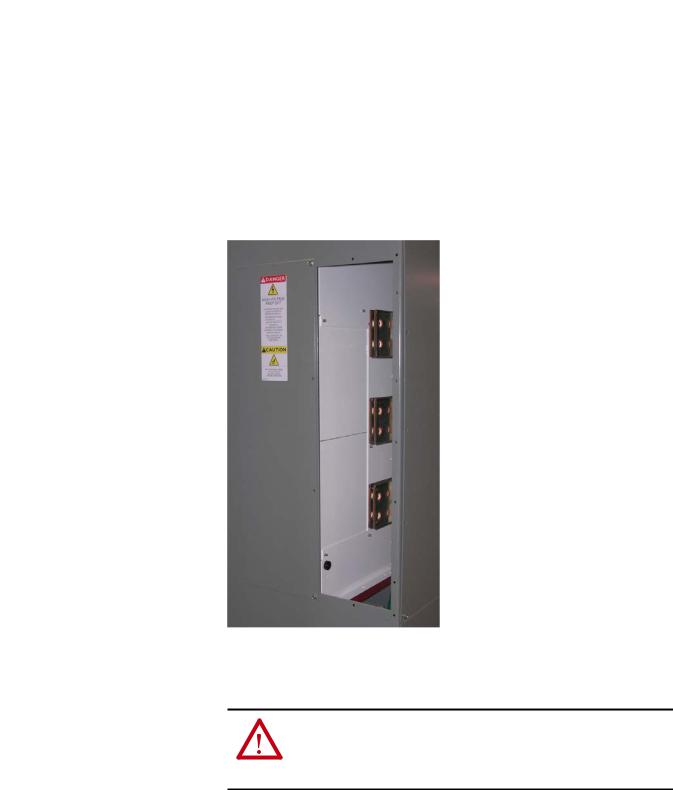
16.To access the right side of the power bus, remove the self-tapping screws from the lower glass-polyester bus access cover and remove the cover (see Figure 15).
Rockwell Automation Publication 1500-UM055G-EN-P - May 2013 |
15 |

Chapter 2 Installation – Standard Enclosure
17.Reverse the procedure to reassemble the cabinet. Ensure that the barriers are put back in place and all parts and tools are accounted for.
Figure 15 - Access to Right Side of Power Bus
Remove self-tapping screws
ATTENTION: Ensure all barriers are replaced before re-energizing the equipment. Failure to do so may result in electrical faults and cause damage to equipment or serious injury to personnel.
Front Access – Bottom Exiting Load Cables
If the cables in your cabinet exit from the bottom, the procedure to access the power bus is almost identical to the one above. Follow the procedure for Top Exiting Load Cables on page 19, but remove the cable duct barrier and cable duct boot from the top of the lower power cell, rather than those at the bottom (see Figure 16).
16 |
Rockwell Automation Publication 1500-UM055G-EN-P - May 2013 |

Installation – Standard Enclosure |
Chapter 2 |
|
|
Figure 16 - Bottom Cable Exit Configuration
Cable Duct Barrier
Cable Duct Boot
Load Cable Connections
ATTENTION: To avoid shock hazards, lock out incoming power (refer to Power Lock-out Procedure on page 47 of Chapter 5) before working on the equipment. Verify with a hot stick or appropriate voltage measuring device that all circuits are voltage free. Failure to do so may result in severe burns, injury or death.
IMPORTANT The current transformers may be positioned for top or bottom cable exit. Follow the appropriate procedure described for your starter configuration.
IMPORTANT Refer to Dimensional Drawings provided with order documentation for additional details.
1.Complete the Power Lock-out procedure (refer to Power Lock-out Procedure on page 47 of Chapter 5).
2.Open the MV power cell door.
3.Remove the cable duct boot at the top of the cabinet for top exiting load cables, or remove the one at the bottom of the cabinet for bottom exiting load cables (see Figure 17).
Rockwell Automation Publication 1500-UM055G-EN-P - May 2013 |
17 |

Chapter 2 Installation – Standard Enclosure
Figure 17 - Access to Load Cable Conduit Openings (Top exit cable configuration shown)
(LV panels removed for clarity)
Remove Cable Duct Boot to access Load Cable Conduit opening for cables exiting from bottom Power Cell
Current Transformer
Mounting Plate
Connect Load Cables to
Current Transformers
4.Remove the appropriate load cable conduit openings in the top or bottom of the cabinet (see Figure 18 or Figure 19).
TIP |
Refer to Dimensional Drawings provided with order documentation for |
|
additional details. |
18 |
Rockwell Automation Publication 1500-UM055G-EN-P - May 2013 |
Installation – Standard Enclosure |
Chapter 2 |
|
|
Top of Cabinet
Load cable Conduit Opening for cables from top power cell
Load Cable Conduit opening for cables from bottom power cell
Ground Lug
Top Exiting Load Cables
5.Load cables for the bottom power cell should be routed first. Pull the cables into the cabinet through the appropriate opening (see Figure 18). Run the cables behind the current transformer mounting plate and into the bottom power cell.
Figure 18 - Load Cable Conduit Openings (Top Exit Shown)
6.For the top power cell, pull the cables into the cabinet through the appropriate opening (see Figure 18).
7.Connect the cables to the current transformers and tighten the connections to 65 N•m (48 lb•ft).
8.Connect cable shields to the ground lug.
9.Reinstall the cable duct boot and reassemble the cabinet.
ATTENTION: Ensure all barriers are replaced before re-energizing the equipment. Failure to do so may result in electrical faults and cause damage to equipment or serious injury to personnel.
Rockwell Automation Publication 1500-UM055G-EN-P - May 2013 |
19 |

Chapter 2 Installation – Standard Enclosure
Bottom Exiting Load Cables
TIP |
Follow steps 1-4 from the previous section. |
5.Load cables for the top power cell should be routed first. Pull the cables into the cabinet through the appropriate opening (see Figure 19). Run the cables behind the current transformer mounting plate and into the top power cell.
Figure 19 - Load Cable Conduit Openings (Bottom Exit Shown)
Load Cable Conduit Opening for cables from top power cell
Load Cable Conduit Opening for cables from bottom power cell
Bottom of Cabinet
6.For the bottom power cell, pull the cables into the cabinet through the appropriate opening (see Figure 19).
7.Connect the cables to the current transformers and tighten the connections to 65 N•m (48 lb•ft).
8.Connect cable shields to the ground lug.
9.Reinstall the cable duct boot and reassemble the cabinet.
ATTENTION: Ensure all barriers are replaced before re-energizing the equipment. Failure to do so may result in electrical faults and cause damage to equipment or serious injury to personnel.
20 |
Rockwell Automation Publication 1500-UM055G-EN-P - May 2013 |

Chapter 3
Installation – Arc-Resistant Enclosure (ArcShield)
This installation section contains information on arc resistant styles of enclosures, referred to in this manual as “ArcShield”.
IMPORTANT For information on the installation site preparation, see Publication
MV-QS050_-EN-P.
ATTENTION: Use suitable personal protective equipment (PPE) per local codes or regulations. Failure to do so may result in severe burns, injury or death.
Door Opening Procedure |
Opening the Low Voltage Doors |
|
|
Low voltage doors are identified as LV in Figure 17 on page 18. |
|
|
1. |
To access the compartments for ArcShield cabinets – turn the release |
|
|
handle counter-clockwise 90º. |
|
2. |
The door is now released and will swing open. |
|
3. |
Reverse the procedure to secure the door. |
Figure 20 - Access to Low Voltage Compartments
Chimney
Upper Low Voltage |
|
|
Door handle |
LV |
MV |
|
LV |
MV |
Lower Low Voltage
Door handle
Plenum
LV |
MV |
LV |
MV |
Upper Low Voltage Door handle
Lower Low Voltage Door handle
Rockwell Automation Publication 1500-UM055G-EN-P - May 2013 |
21 |

Chapter 3 Installation – Arc-Resistant Enclosure (ArcShield)
Opening the Medium Voltage Doors
ATTENTION: Complete the Power Lock-out procedure (refer to Power Lock-out Procedure on page 47 of Chapter 5) before beginning any service procedures to the unit. Failure to do so may result in severe burns, injury or death.
Medium voltage doors are identified as MV in Figure 21.
Figure 21 - Access to Medium Voltage Compartments
Chimney |
|
Upper Low Voltage |
|
Door handle |
|
LV |
MV |
Lower Low Voltage |
|
Door handle |
|
LV |
MV |
Plenum
LV |
MV |
LV |
MV |
Upper Low Voltage Door handle
Lower Low Voltage Door handle
IMPORTANT Each medium voltage door has its own isolation switch handle and interlocking safeguards. Upper and lower power cells are separated by an isolation barrier.
Refer to Access to the Power Bus on page 26 for the procedure to open the swingout low voltage panel behind the low voltage door (for standard cabinet only).
1.Electrically open the contactor by pressing the STOP button on the starter or at the remote control location.
2.Move the isolation switch handle to the OFF position (see Figure 22).
3.Turn the release handle counter-clockwise 90 degrees.
4.Unbolt the door locking bolts for medium voltage door.
5.The door is now released and will swing open.
22 |
Rockwell Automation Publication 1500-UM055G-EN-P - May 2013 |
Loading...