


Reference Manual
Bulletin 1606 Switched Mode Power Supplies
Catalog Number: 1606-XLS240-UPS
Index
1. |
Description ............................................................... |
1 |
17. |
EMC ........................................................................ |
16 |
2. |
Specification Quick Reference ............................ |
1 |
18. |
Environment ....................................................... |
17 |
3. |
Catalog Numbers ................................................... |
1 |
19. |
Protection Features .......................................... |
17 |
4. |
Certification Marks .................................................. |
1 |
20. |
Safety .................................................................... |
18 |
5. |
Input ............................................................................. |
4 |
21. |
Certifications ................................................. |
18 |
6. |
Output in Normal Mode ....................................... |
5 |
22. |
Environmental Compliance ........................... |
19 |
7. |
Output in Buffer Mode .......................................... |
6 |
23. |
Physical Dimensions and Weight ................. |
19 |
8. |
Battery Input ............................................................. |
7 |
24. |
Installation Notes ............................................. |
20 |
9. |
Buffer Time ................................................................ |
8 |
25. |
Accessories ........................................................... |
21 |
10. |
Efficiency and Power Losses .............................. |
10 |
26. |
Application Notes .............................................. |
22 |
11. |
Functional Diagram ............................................. |
10 |
|
26.1. Battery Replacement Intervals .......... |
22 |
12. |
Check Wiring and Battery Quality Tests ....... |
10 |
|
26.2. Parallel and Serial Use ......................... |
23 |
13. |
Relay Contacts and Inhibit Input .................... |
12 |
|
26.3. Using the Inhibit Input ........................ |
24 |
14. |
Front Side User Elements .................................. |
14 |
|
26.4. Troubleshooting ................................... |
24 |
15. |
Terminals and Wiring ........................................ |
15 |
|
|
|
16. |
Reliability ........................................................... |
15 |
|
|
|
Terminology and Abbreviations
•DC-UPS—Uninterruptible power supply with DC Input.
•Normal mode—Describes a condition in which the battery is charged, the input voltage is in range and the output is loaded within the allowed limits.
•Buffer mode—Describes a condition where the input voltage is below the transfer threshold level, the unit is running on battery (buffering) and the output is loaded within the allowed limits.
•Charging mode—Describes a condition where the battery is in the process of charging, the input voltage is in range and the output is loaded within the allowed limits.
•Inhibit mode—Describes a condition where buffering is intentionally disabled by using the inhibit input of the DC UPS (e.g. to perform service actions or to save battery capacity).
•Buffer time—This term is equivalent to “hold-up time.”
•T.b.d.—To be defined, value or description will follow later.
Bulletin 1606 Switched Mode Power Supplies
DC-UPS Control Unit
■ Requires Only One 12V Battery for a 24V Output ■ Stable Output Voltage in Buffer Mode
■ Superior Battery Management for Longest Battery Life ■ Comprehensive Diagnostic and Monitoring Functions ■ Replace Battery Signal Included
■ Electronically Overload and Short Circuit Protected ■ 50% Power Reserves
■ Selectable Buffer Time Limiter ■ 3 Year Warranty
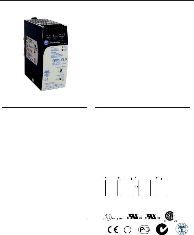
 1. Description
This uninterruptible power supply (UPS) controller 1606-XLS240-UPS is an addition to standard 24V power supplies to bridge power failures or voltage fluctuations. Expensive downtimes, long restart cycles and loss of data can be avoided.
The DC-UPS includes a professional battery management system which charges and monitors the battery to achieve the longest battery service life as well as many diagnostic functions that ensure a reliable operation of the entire system.
A unique feature of the 1606-XLS240-UPS is that only one 12V battery is required to buffer the 24V output. This makes matching batteries unnecessary and allows a precise battery charging and testing.
The 1606-XLS240-UPS requires one external 12V battery for which two preassembled battery modules are available: a lightweight 7Ah battery that can be mounted on the DIN rail and a 26Ah module that can be panel-mounted for longer buffer times.
In addition to the 1606-XLS240-UPS, the 1606-XLS240-UPSC UPS includes the same controller with an integrated 5Ah battery.
 2. Specification Quick Reference
Input voltage |
nom. 24Vdc |
|
|
range |
22.5-30Vdc |
|
|
Output current |
min.15A |
Normal mode |
|
|
min. 10A |
Buffer mode |
|
Output voltage |
typ. 0.23V lower |
Normal mode |
|
|
as input voltage |
|
|
|
22.25V |
Buffer mode, 10A |
|
Allowed batteries |
3.9Ah to 40Ah |
VRLA lead acid |
|
Temperature range |
-25 to +70°C |
Operational |
|
Derating |
0.43A/°C |
+60°C to +70°C |
|
normal mode |
|||
|
|
||
Dimensions |
49x124x117mm |
WxHxD |
|
Buffer time (at 10A) |
typ. 6’45” |
7Ah battery module |
|
|
typ. 55’ |
26Ah batt. module |
Typical setup of a DC-UPS system with the 1606-XLS240-UPS:
AC |
DC |
24V |
24V |
|
- |
|
e.g.: PLC |
|
3. Catalog Numbers |
|
|
|
4. Certification Marks |
|
DC-UPS 1606-XLS240-UPS |
Standard controller |
|
|
|
|
|
|
|||
|
|
||||
Accessories 1606-XLSBATASSY1 |
Battery module 12V |
7Ah |
1606-XLSBATBR1 |
Mounting kit w/o battery |
|
1606-XLSBATASSY2 |
Battery module 12V |
26Ah |
1606-XLSBATBR2 |
Mounting kit w/o battery |
|
IND. CONT. EQ. UL 60950-1 Class I Div 2 |
|
|||
UL 508 |
|
|
|
|
|
GL |
|
|
|
EMC, LVD |
Marine |
GOST R |
C-Tick |
Marine RINA |
|
|
|||
1606-XLB |
Panel/Wall mount bracket |
|
All parameters are specified at 24V, 10A output load and after a 5 minutes run-in time unless noted otherwise. |
|
It is assumed that the input power source can deliver a sufficient output current |
2 |
Rockwell Automation Publication 1606-RM036A-EN-P — April 2014 |
Bulletin 1606 Switched Mode Power Supplies
Intended Use
•This device is designed for installation in an enclosure and is intended for the general professional use such as in industrial control, office, communication, and instrumentation equipment.
•Do not use this power supply in aircraft, trains, nuclear equipment or similar systems where malfunction may cause severe personal injury or threaten human life.
•This device is designed for use in non-hazardous, ordinary or unclassified locations.
Installation Requirements
•This device may only be installed and put into operation by qualified personnel.
•This device does not contain serviceable parts. The tripping of an internal fuse is caused by an internal defect.
•If damage or malfunction should occur during installation or operation, immediately turn power off and send unit to the factory for inspection.
•Mount the unit on a DIN rail so that the terminals are located on the bottom of the unit.
•This device is designed for convection cooling and does not require an external fan. Do not obstruct airflow and do not cover ventilation grid (e.g. cable conduits) by more than 30%!
•Keep the following installation clearances: 40mm on top, 20mm on the bottom, 5mm on the left and right sides are recommended when the device is loaded permanently with more than 50% of the rated power. Increase this clearance to 15mm in case the adjacent device is a heat source (e.g. another power supply).
SHOCK HAZARD: Do not use the power supply without proper grounding (Protective Earth). Use the terminal on the input block for earth connection and not one of the screws on the housing.
-Turn power off before working on the device. Protect against inadvertent re-powering
-Make sure that the wiring is correct by following all local and national codes
-Do not modify or repair the unit
-Do not open the unit as high voltages are present inside
-Use caution to prevent any foreign objects from entering the housing
-Do not use in wet locations or in areas where moisture or condensation can be expected
-Do not touch during power-on, and immediately after power-off. Hot surfaces may cause burns.
WARNING: EXPLOSION HAZARDS!
Substitution of components may impair suitability for this environment. Do not disconnect the unit or operate the voltage adjustment or S/P jumper unless power has been switched off or the area is known to be non-hazardous.
All parameters are specified at 24V, 10A output load, 25°C ambient and after a 5 minutes run-in time unless noted otherwise. |
|
It is assumed that the input power source can deliver a sufficient output current. |
|
Rockwell Automation Publication 1606-RM036A-EN-P — April 2014 |
3 |
Bulletin 1606 Switched Mode Power Supplies
|
5. |
Input |
|
|
|
|
|
|
Input voltage |
nom. |
DC 24V |
|
|
|
|
|
||||
|
|
Input voltage ranges |
nom. |
22.5 to 30Vdc |
Continuous operation, see Fig. 5-1 |
|
|
|
|
|
|
30 to 35Vdc |
Temporarily allowed, no damage to the DC-UPS *) |
|
|
|
|
|
35Vdc |
Absolute maximum input voltage with no damage to the |
|
|
|
|
|
|
DC-UPS |
|
|
|
|
|
0 to 22.5Vdc |
The DC-UPS switches into buffer mode and delivers |
|
|
|
|
|
|
output voltage from the battery if the input was above |
|
|
|
|
|
|
the turn-on level before and all other buffer conditions |
|
|
|
|
|
|
are fulfilled. |
|
|
Allowed input voltage ripple |
max. |
1.5Vpp |
Bandwidth <400Hz |
|
|
|
|
|
|
1Vpp |
Bandwidth 400Hz to 1kHz |
|
|
Allowed voltage between input |
max. |
60Vdc or |
|
|
|
|
and earth (ground) |
|
42.4Vac |
|
|
|
|
Turn-on voltage |
typ. |
22.8Vdc |
The output does not switch on if the input voltage does |
|
|
|
|
|
|
|
not exceed this level. |
|
|
|
|
max. |
23Vdc |
|
|
|
Input current **) |
typ. |
120mA |
Internal current consumption |
|
|
|
|
|
typ. |
1.1A |
Current consumption for battery charging in constant |
|
|
|
|
|
|
current mode at 24V input See Fig. 8-2 ***) |
|
|
External capacitors on the input |
|
No limitation |
|
|
*) |
The DC-UPS shows “Check Wiring” with the red LED and buffering is not possible |
|||||
**) |
The total input current is the sum of the output current plus the current required to charge the battery during the charging |
|||||
|
|
|
process and the current which is needed to supply the DC-UPS itself. See also Fig. 5-2. This calculation does not apply |
|||
|
|
|
in overload situations where the DC-UPS limits the output current, therefore see Fig. 5-3. |
|||
***) Please note: This is the input current and not the current flowing into the battery in the process of charging. The battery current is indicated in section 8.
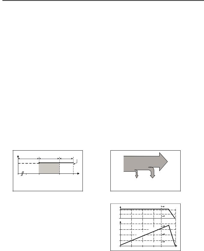
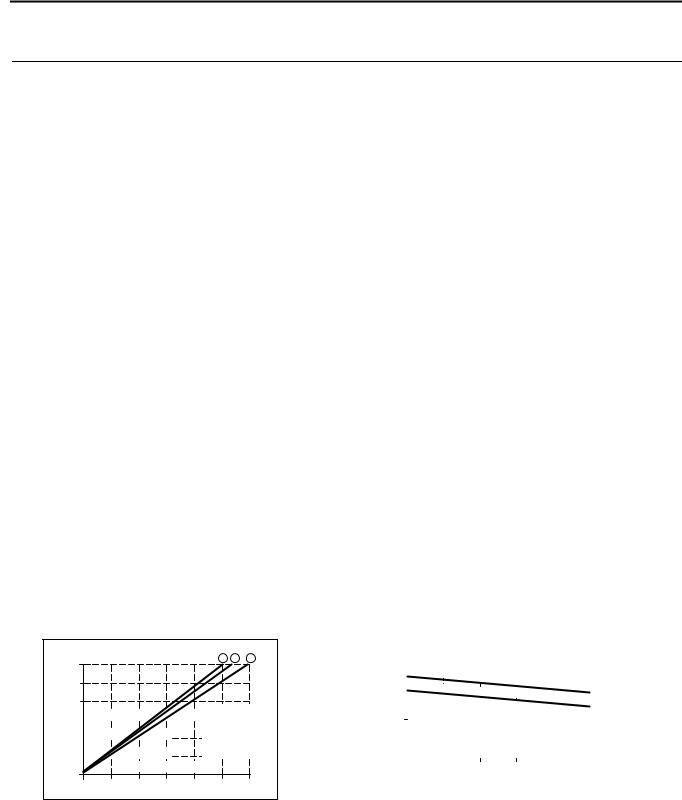
Fig. 5-1 Input voltage range |
Fig. 5-2 Input current, definitions |
V OUT |
D |
|
A |
B |
C |
|
|
|
Output |
||||
|
|
|
|
|
Input |
|
|
|
|
|
|
Current |
Current |
|
|
|
|
|
VIN |
|
0 |
18 |
22.5 |
30 |
|
35V |
|
A: Rated input voltage range |
|
Internal |
Current |
|||
B: Temp. allowed, no harm to the unit |
|
current |
consumption |
|||
C: Absolute max. input voltage |
|
consumption |
for battery |
|||
|
|
charging |
||||
D: Buffer mode |
|
|
|
|
||
|
|
|
|
|
||
Electronic output current limitation
The DC-UPS is equipped with an electronic output current limitation. This current limitation works in a switching mode which reduces the power losses and heat generation to a minimum. As a result, the output voltage drops since there is not enough current to support the load. A positive effect of the current limit ation in switching mode is that the input current goes down despite an increase in the output current resulting in less stress for the supplying source.
Fig. 5-3 Input current and output voltage vs. output current, typ. (battery fully charged)
|
Output Voltage |
|
|
|
Overload |
|||
20V |
|
|
|
|
|
|
|
|
10 |
|
|
|
|
|
|
|
|
20A |
|
|
|
|
|
|
|
|
15 |
|
|
|
|
|
t |
|
|
|
|
|
|
|
ren |
|
|
|
|
|
|
|
|
r |
|
|
|
|
|
|
|
u |
|
|
|
|
|
|
|
|
t C |
|
|
|
|
10 |
|
|
u |
|
|
|
|
|
|
p |
|
|
|
|
|
||
|
In |
|
|
|
|
|
|
|
5 |
|
Ou t pu t Cu r re n t |
|
|
||||
0 |
|
|
|
|||||
4 |
|
8 |
|
|
12 |
15 |
20A |
|
0 |
|
|
|
|||||
|
All parameters are specified at 24V, 10A output load, 25°C ambient and after a 5 minutes run-in time unless noted otherwise. |
|
It is assumed that the input power source can deliver a sufficient output current. |
4 |
Rockwell Automation Publication 1606-RM036A-EN-P — April 2014 |
|
|
|
|
|
|
Bulletin 1606 Switched Mode Power Supplies |
|
|
|
|
|
|
|
|
|
|
6. Output in Normal Mode |
|
|
|
|
|
|
|
|
||
|
|
|
Output voltage in normal mode |
nom. |
DC 24V |
The output voltage follows the input voltage reduced by |
|
|
|
||||
|
|
|
|
|
|
the input to output voltage drop. |
|
|
|
Voltage drop between input and |
max. |
0.3V |
At 10A output current, see Fig. 6-1 for typical values |
|
|
|
output |
|
|
|
|
|
|
|
max. |
0.45V |
At 15A output current, see Fig. 6-1 for typical values |
|
|
|
Ripple and noise voltage |
max. |
20mVpp |
20Hz to 20MHz, 50Ohm *) |
|
|
|
Output current |
nom. |
15A |
Continuously allowed |
|
|
|
Output power |
nom. |
360W |
Continuously allowed |
|
|
|
Short-circuit current |
min. |
17.9A |
Load impedance 100mOhm, see Fig. 6-2 for typical values |
|
|
|
|
max. |
21A |
Load impedance 100mOhm, see Fig. 6-2 for typical values |
|
|
|
Capacitive and inductive loads |
|
No limitation |
|
*) This figure shows the ripple and noise voltage which is generated by the DC-UPS. The ripple and noise voltage might be higher if the supplying source has a higher ripple and noise voltage.
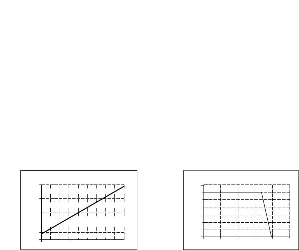
Fig. 6-1 Input to output voltage drop, typ.
Input to Output Voltage drop
0.4V
0.35 


 0.3
0.3
0.25 


 0.2
0.2
0.15 


 0.1
0.1 


0.05 Ou t pu t Cu r re n t 0 


0 2 4 6 8 10 12 14 16 18A
Fig. 6-2 Output voltage vs. output current in normal mode at 24V input, typ.
Output Voltage
28V |
|
|
|
|
|
24 |
|
|
|
|
|
20 |
|
|
|
|
|
16 |
|
|
|
|
|
12 |
|
|
|
|
|
8 |
|
|
|
|
|
4 |
|
Output Current |
|
|
|
0 |
|
|
|
|
|
|
|
|
|
|
|
0 |
5 |
10 |
15 |
20 |
25A |
All parameters are specified at 24V, 10A output load, 25°C ambient and after a 5 minutes run-in time unless noted otherwise. |
|
It is assumed that the input power source can deliver a sufficient output current. |
|
Rockwell Automation Publication 1606-RM036A-EN-P — April 2014 |
5 |

Bulletin 1606 Switched Mode Power Supplies
 7. Output in Buffer Mode
If the input voltage falls below a certain value (transfer threshold level), the DC-UPS starts buffering without any interruption or voltage dips. Buffering is possible even if the battery is not fully charged.
Output voltage in buffer mode |
nom. |
DC 24V |
Output voltage is stabilized and independent from |
|
|
|
battery voltage |
|
|
22.45V |
±1%, at no load, |
|
|
22.25V |
±1%, at 10A output current |
Transfer threshold for buffering |
typ. |
80mV higher than the output voltage in buffer mode |
|
Ripple and noise voltage |
max. |
20mVpp |
20Hz to 20MHz, 50Ohm |
Output current |
nom. |
10A |
Continuously allowed |
|
|
15A |
< 5s with full output voltage *) |
Short-circuit current |
min. |
17.9A |
Load impedance 100mOhm **) |
|
max. |
21A |
Load impedance 100mOhm **) |
*) |
If the output current is in the range between 10A and 15A for longer than 5s, a hardware controlled reduction of the |
|
|
maximal output current to 10A occurs. If the 10A are not sufficient to maintain the 24V, buffering stops after another 5s. |
|
|
Buffering is possible again as soon as the input voltage recovers. |
|
**) |
If the nominal output voltage cannot be maintained in buffer mode, the DC-UPS switches off after 5s to save battery |
|
|
capacity. |
|
|
Fig. 7-1 Buffering transition, definitions |
Fig. 7-2 Transfer behavior, typ. |
Input |
28V |
|
|
|
|
|
|
Output |
|
|
|
|
|
|
Voltage |
||
voltage |
24V |
Transfer |
|
|
|
|
|
|
|
|
|
|
|
|
|||
|
|
threshold |
|
2 4V |
2 |
. 25 V |
a t 1 |
2 4V |
|
|
|
|
2 |
0A |
|||
|
|
|
t |
|
|
|
|
|
Output |
|
|
|
|
|
|
|
|
voltage |
|
|
|
|
|
|
|
|
|
|
Buffer mode |
|
0V |
|
Input Voltage |
||
|
|
t |
|
|
|
|
||
|
|
|
|
|
|
|
||
|
|
|
|
|
|
500m s/DIV |
||
|
|
|
|
|
|
|
||
Fig. 7-3 Available output current in buffer mode
|
Output |
|
Current |
15A |
BonusPower |
10A |
|
5A |
|
0 |
Time |
|
|
0 |
5 Sec. |
Fig. 7-4 Output voltage vs. output current in buffer mode, typ.
Output Voltage
25V |
|
A |
B |
|
|
|
20 |
|
|
|
|||
|
|
|
|
|
||
15 |
|
D |
|
C |
|
|
10 |
|
|
|
|||
|
|
|
|
|
||
5 |
|
|
|
|
Output |
|
0 |
|
|
|
|
Current |
|
5 |
10 |
15 |
20 |
25A |
||
0 |
AContinuously available
BAvailable for 5s then auto switching to curveD
CBuffering will stop after 5s.
DBuffering will stop after 5s.
|
All parameters are specified at 24V, 10A output load, 25°C ambient and after a 5 minutes run-in time unless noted otherwise. |
|
It is assumed that the input power source can deliver a sufficient output current. |
6 |
Rockwell Automation Publication 1606-RM036A-EN-P — April 2014 |
Bulletin 1606 Switched Mode Power Supplies


 8. Battery Input
The DC-UPS requires one 12V VRLA battery to buffer the 24V output.
Battery voltage |
nom. |
DC 12V |
Use one maintenance-free 12V VRLA lead acid battery or |
|
|
|
one battery module which is listed in the Accessories |
|
|
|
section. |
Battery voltage range |
|
9.0 – 15.0V |
Continuously allowed, except deep discharge protection |
|
max. |
35Vdc |
Absolute maximum voltage with no damage to the unit |
|
typ. |
7.4V |
Above this voltage level battery charging is possible. |
Allowed battery sizes |
min. |
3.9Ah |
|
|
max. |
40Ah |
|
Internal battery resistance |
max. |
100mOhm |
See individual battery datasheets for this value. |
Battery charging method |
|
CC-CV |
Constant current, constant voltage mode |
Battery charging current (CC-mode) |
nom. |
1.5A |
Independent from battery size, |
|
max. |
1.7A |
Corresponding 24V input current see Fig. 8-2 |
End-of-charge-voltage (CV-mode) |
|
13.4-13.9V |
Adjustable, see section 14. |
Battery charging time |
typ. |
5h *) |
For a 7Ah battery |
|
typ. |
17h *) |
For a 26Ah battery |
Battery discharging current **) |
typ. |
21A |
Buffer mode, 10A output current, 11.5V on the battery |
|
|
|
terminal of the DC-UPS, see Fig. 8-1 for other parameters |
|
typ. |
0.3A |
Buffer mode, 0A output current |
|
max. |
50μA |
At no input, buffering had switched off, all LEDs are off |
|
typ. |
270mA |
At no input, buffering had switched off, yellow LED |
|
|
|
shows “buffer time expired” (max. 15 minutes) |
Deep discharge protection ***) |
typ. |
10.5V |
At 0A output current |
|
typ. |
9.0V |
At 10A output current |
*) The charging time depends on the duration and load current of the last buffer event. The numbers in the table represent a fully discharged battery. A typical figure for a buffer current of 10A is 3h 20 min (200 min) for a 7Ah battery.
**) The current between the battery and the DC-UPS is more than twice the output current. This is caused by boosting the 12V battery voltage to a 24V level. This high current requires large wire gauges and short cable length for the longest possible buffer time. The higher the resistance of the connection between the battery and the DC-UPS, the lower the voltage on the battery terminals which increases the discharging current. See also section 25 for further installation instructions.
***) To ensure longest battery lifetime, the DC-UPS has a battery deep discharge protection feature included. The DC-UPS stops buffering when the voltage on the battery terminals of the DC-UPS falls below a certain value. The yellow LED will show “buffer time expired” for a period of 15 minutes after the unit stopped buffering.
Fig. 8-1 Battery discharging current vs. output current, typ.
Battery Current
30A
25
20
15 


10 


5 


Output 0
A B C
Voltage on 


 battery terminal of the DC-UPS:
A:10.5V
B:11V
C:12V
Current
0 |
2.5 |
5 |
7.5 |
10 |
12.5 |
15A |
Fig. 8-2 Required input current vs. input voltage for battery charging
Input Current |
|
|
|
|
|
|
|
|
|
|
|
|
|
|
|
|
|
|
|
|
|
|
|
|
|
|
|
|
|
|
|
|
|
||||||||||
1.5A |
|
|
|
|
|
|
|
|
|
|
|
|
|
|
|
|
|
|
|
|
|
|
|
|
|
|
|
|
|
|
|
|
|
|
|
|
|
|
|
|
|
|
|
|
|
|
|
|
|
|
|
|
|
|
|
|
|
|
|
|
|
|
|
|
|
|
|
|
|
|
|
|
|
|
|
|
|
|
|
|
|
|
|
|
|
|
|
1.25 |
|
|
|
|
|
max. (battery |
|
|
|
|
|
|
|
|
|
|
|
|
|
|
|
|
|
|
|
|
|
|
|
|
|
|
|||||||||||
|
|
|
|
|
|
|
|
|
|
|
|
|
|
|
|
|
|
|
|||||||||||||||||||||||||
|
|
|
|
|
|
|
|
|
|
|
|
|
|
|
|
|
|
|
chargin |
|
|
|
|
|
|
|
|
|
|
|
|
|
|
|
|
|
|
||||||
|
|
|
|
|
|
|
|
|
|
|
|
|
|
|
|
|
|
|
|
|
|
|
|
|
|
|
|
|
|
|
|
|
|
|
|
|
|
|
|
|
|
|
|
|
|
|
|
|
|
|
typ. (battery |
|
|
|
|
|
|
|
|
|
|
|
|
|
|
|
|
|
|
|
|
|
|
|
|
|
|||||||||||
|
|
|
|
|
|
|
|
|
|
|
|
|
|
|
|
|
|
|
|
|
|
|
|
|
|
|
|
|
|
|
|
|
|||||||||||
|
|
|
|
|
|
|
|
|
|
|
|
|
|
|
|
|
|
|
|
charging cu |
|
|
|
|
|
|
|
|
|
|
|||||||||||||
1.0 |
|
|
|
|
|
|
|
|
|
|
|
|
|
|
|
|
|
|
|
|
|
|
|
|
|
|
|
|
|
|
rrent 1.5A) |
|
|||||||||||
|
|
|
|
|
|
|
|
|
|
|
|
|
|
|
|
|
|
|
|
|
|
|
|
|
|
|
|
|
|
|
|
|
|
|
|
|
|
|
|
|
|
|
|
0.75 |
|
|
|
|
|
|
|
|
|
|
|
|
|
|
|
|
|
|
|
|
|
|
|
|
|
|
|
|
|
|
|
|
|
|
|
|
|
|
|
|
|
|
|
|
|
|
|
|
|
|
|
|
|
|
|
|
|
|
|
|
|
|
|
|
|
|
|
|
|
|
|
|
|
|
|
|
|
|
|
|
|
|
|
|
|
|
|
|
|
|
|
|
|
|
|
|
|
|
|
|
|
|
|
|
|
|
|
|
|
|
|
|
|
|
|
|
|
|
|
|
|
|
|
|
|
|
|
|
|
|
|
0.5 |
|
|
|
|
|
|
|
|
|
|
|
|
|
|
|
|
|
|
|
|
|
|
|
|
|
|
|
|
|
|
|
|
|
|
|
|
|
|
|
|
|
|
|
|
|
|
|
|
|
|
|
|
|
|
|
|
|
|
|
|
|
|
|
|
|
|
|
|
|
|
|
|
|
|
|
|
|
|
|
|
|
|
|
|
|
|
|
|
|
|
|
|
|
|
|
|
|
|
|
|
|
|
|
|
|
|
|
|
|
|
|
|
|
|
|
|
|
|
|
|
|
|
|
|
|
|
|
|
|
|
|
0.25 |
|
|
|
|
|
|
|
|
|
|
|
|
|
|
|
|
|
|
|
|
|
|
|
|
|
|
|
|
|
|
|
|
|
|
|
|
|
|
|
|
|
|
|
|
|
|
|
|
|
|
|
|
|
|
|
|
|
|
|
|
|
|
|
|
|
|
|
|
|
|
|
|
|
|
|
|
|
|
|
|
|
|
|
|
|
|
|
|
|
|
|
|
|
|
|
|
|
|
Input |
|
Voltage |
|
|
|
|
|
|
|
|
|
|
|
|
|
|
|
|
|
|||||||||||||
0 |
|
|
|
|
|
|
|
|
|
|
|
|
|
|
|
|
|
|
|
|
|
|
|
|
|
|
|
|
|
||||||||||||||
|
|
|
|
|
|
|
|
|
|
|
|
|
|
|
|
|
|
|
|
|
|
|
|
|
|
|
|
|
|
|
|
|
|
|
|
|
|
|
|
|
|
|
|
23 |
24 |
25 |
26 |
|
|
27 |
|
|
|
28V |
|||||||||||||||||||||||||||||||||
|
|
|
|
|
|
|
|
|
|
|
|
|
|
|
|
|
|
|
|
|
|
|
|
|
|
|
|
|
|
|
|
|
|
|
|
|
|
|
|
|
|
|
|
All parameters are specified at 24V, 10A output load, 25°C ambient and after a 5 minutes run-in time unless noted otherwise. |
|
It is assumed that the input power source can deliver a sufficient output current. |
|
Rockwell Automation Publication 1606-RM036A-EN-P — April 2014 |
7 |
Bulletin 1606 Switched Mode Power Supplies


 9. Buffer Time
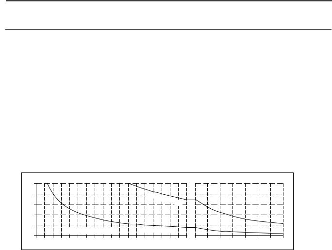
The buffer time depends on the capacity and performance of the battery as well as the load current. The diagram below shows the typical buffer times of the standard battery modules.
Buffer time with battery module 1606-XLSBATASSY1 |
min. |
19’12’’ |
At 5A output current *) |
|
|
min. |
5’42’’ |
At 10A output current *) |
|
|
typ. |
21’30’’ |
At 5A output current, see |
Fig. 9-1 **) |
|
typ. |
6’45’’ |
At 10A output current, see |
Fig. 9-1 **) |
Buffer time with battery module 1606-XLSBATASSY2 |
min. |
99’30’’ |
At 5A output current *) |
|
|
min. |
39’ |
At 10A output current *) |
|
|
typ. |
130’ |
At 5A output current, see |
Fig. 9-1 **) |
|
typ. |
55’ |
At 10A output current, see |
Fig. 9-1 **) |
*) |
Minimum value includes 20% aging of the battery and a cable length of 1.5m with a cross section of 2.5mm 2 between the |
|
battery and the DC-UPS and requires a fully charged (min. 24h) battery. |
**) |
Typical value includes 10% aging of the battery and a cable length of 0.3m with a cross section of 2.5mm 2 between the battery |
|
and the DC-UPS and requires a fully charged (min. 24h) battery. |
|
Fig. 9-1 Buffer time vs. output current with the battery modules 1606-XLSBATASSY1 and 1606-XLSBATASSY2 |
Buffer Current |
|
|
|
|
|
|
|
|
|
|
|
|
|
|
|
|
|
|
|
|
|
|
|
|
|
|
|
|
|
10A |
|
|
|
|
|
|
|
|
|
|
|
|
|
|
|
|
|
|
|
|
|
|
|
|
|
|
|
|
|
8 |
|
|
|
|
|
|
|
|
|
|
|
|
12V |
26 |
Ah |
|
|
|
|
|
|
|
|
|
|
|
|
|
|
|
|
|
|
|
|
|
|
|
|
|
|
|
|
|
|
|
|
|
|
|
|
|
|
|
|
||||
|
|
|
|
|
|
|
|
|
|
|
|
|
|
|
|
|
|
|
|
|
|
|
|
|
|
|
|||
|
|
|
|
|
|
|
|
|
|
|
|
|
|
|
|
bat |
|
|
|
|
|
|
|
|
|
|
|
|
|
|
|
|
|
|
|
|
|
|
|
|
|
|
|
|
|
|
te |
|
|
|
|
|
|
|
|
|
|
|
|
6 |
|
|
|
|
|
|
|
|
|
|
|
|
|
|
|
|
|
ry |
|
|
|
|
|
|
|
|
|
|
|
|
|
|
|
|
|
|
|
|
|
|
|
|
|
|
|
|
|
|
|
|
|
|
|
|
|
|
|
|
|
4 |
|
|
|
|
|
|
|
|
|
|
|
|
|
|
|
|
|
|
|
|
|
|
|
1606-XL |
|
|
|
|
|
|
|
|
|
|
|
|
|
|
|
|
|
|
|
|
|
|
|
|
|
|
|
|
|
|
SBAT |
t |
|
|
|
|
|
|
|
|
|
|
|
|
|
|
|
1606-XLSB |
|
|
|
|
|
|
|
|
|
|
2 |
y p. |
|||||
|
|
|
|
|
|
|
|
|
|
|
|
|
|
|
|
|
|
|
|
|
|
|
|
||||||
2 |
|
|
|
|
|
|
|
|
|
|
|
|
|
|
AT1 typ. |
|
|
|
|
|
|
|
|
|
|
|
|
||
|
|
Buffer Time (Minutes) |
|
|
|
12V 7Ah battery |
|
|
|
|
|
|
1606-XLSBAT1 typ. |
|
|||||||||||||||
|
|
|
|
|
|
|
|
|
|
|
|
|
|||||||||||||||||
5 |
10 |
15 |
20 |
25 |
30 |
35 |
40 |
45 |
50 |
55 |
60 |
65 |
70 |
75 |
80 |
85 |
90 |
90 |
120 |
150 |
180 |
210 |
240 |
270 |
|
300 |
|||
|
|
|
|
|
|
|
|
|
|
|
|
|
|
|
|
|
|
|
|
|
|
|
|
|
|
|
|
|
Min. |
The battery capacity is usually specified in amp-hours (Ah) for a 20h discharging event. The battery discharge is nonlinear (due to the battery chemistry). The higher the discharging current, the lower the appropriate battery capacity. The magnitude of the reduction depends on the discharging current as well as on the type of battery. High current battery types can have up to 50% longer buffer times compared to regular batteries when batteries are discharged in less than 1 hour.
High discharging currents do not necessarily mean high power losses as the appropriable battery capacity is reduced with such currents. When the battery begins to recharge after a discharging event, the process is completed much faster since only the energy which was taken out of the battery needs to be “replenished.”
For this reason, the buffer time cannot be calculated using the Ah capacity value. The equation “l x t = capacity” in Ah generally leads to incorrect results when the discharging current is higher than C20 (discharging current for 20h). Study the battery datasheet and determine the expected buffer time by using the example on the next page.
|
All parameters are specified at 24V, 10A output load, 25°C ambient and after a 5 minutes run-in time unless noted otherwise. |
|
It is assumed that the input power source can deliver a sufficient output current. |
8 |
Rockwell Automation Publication 1606-RM036A-EN-P — April 2014 |
 Loading...