


1746-NR4
Table of contents
 Loading...
SLC 500
RTD/Resistance
Input Module
1746-NR4
User Manual

Important User Information
Solid state equipment has operational characteristics differing from those of
electromechanical equipment. Safety Guidelines for the Application,
Installation and Maintenance of Solid State Controls (publication SGI-1.1
available from your local Rockwell Automation sales office or online at
http://literature.rockwellautomation.com
) describes some important
differences between solid state equipment and hard-wired electromechanical
devices. Because of this difference, and also because of the wide variety of
uses for solid state equipment, all persons responsible for applying this
equipment must satisfy themselves that each intended application of this
equipment is acceptable.
In no event will Rockwell Automation, Inc. be responsible or liable for
indirect or consequential damages resulting from the use or application of
this equipment.
The examples and diagrams in this manual are included solely for illustrative
purposes. Because of the many variables and requirements associated with
any particular installation, Rockwell Automation, Inc. cannot assume
responsibility or liability for actual use based on the examples and diagrams.
No patent liability is assumed by Rockwell Automation, Inc. with respect to
use of information, circuits, equipment, or software described in this manual.
Reproduction of the contents of this manual, in whole or in part, without
written permission of Rockwell Automation, Inc., is prohibited.
Throughout this manual, when necessary, we use notes to make you aware
of safety considerations.
Rockwell Automation, Allen-Bradley, TechConnect, ControlLogix, RSLogix 500, and RSLinx are trademarks of Rockwell
Automation, Inc.
Trademarks not belonging to Rockwell Automation are property of their respective companies.
WARNING
Identifies information about practices or circumstances that can cause
an explosion in a hazardous environment, which may lead to personal
injury or death, property damage, or economic loss.
IMPORTANT
Identifies information that is critical for successful application and
understanding of the product.
ATTENTION
Identifies information about practices or circumstances that can lead
to personal injury or death, property damage, or economic loss.
Attentions help you identify a hazard, avoid a hazard, and recognize
the consequence
SHOCK HAZARD
Labels may be on or inside the equipment, for example, a drive or
motor, to alert people that dangerous voltage may be present.
BURN HAZARD
Labels may be on or inside the equipment, for example, a drive or
motor, to alert people that surfaces may be dangerous temperatures.

3 Publication 1746-UM008B-EN-P - December 2006
Summary of Changes
New Information
The information below summarizes the changes to this manual since
the last revision.
The table below lists sections that document new features and
additional information about existing features and shows where to
find this new information.
Change Page
Moved terms and abbreviations from
Preface to Glossary.
Preface
Updated programming examples to show
RSLogix 500 software.
Throughout manual
Updated programming examples. Chapter 6
Updated programming examples. Chapter 8
Added Appendix D, I/O configuration. Appendix D, page 131

Publication 1746-UM008B-EN-P - December 2006
4 Summary of Changes
Notes:

5 Publication 1746-UM008B-EN-P - December 2006
Table of Contents
Preface
Use This Manual . . . . . . . . . . . . . . . . . . . . . . . . . . . . . . . . . . 7
Who Should Use This Manual . . . . . . . . . . . . . . . . . . . . . . . . 7
Purpose of This Manual. . . . . . . . . . . . . . . . . . . . . . . . . . . . . 7
Common Techniques Used in This Manual. . . . . . . . . . . . . . . 9
Chapter 1
Overview
Description. . . . . . . . . . . . . . . . . . . . . . . . . . . . . . . . . . . . . 11
System Overview . . . . . . . . . . . . . . . . . . . . . . . . . . . . . . . . 18
Chapter 2
Quick Start Guide
Required Tools and Equipment . . . . . . . . . . . . . . . . . . . . . 23
Procedures . . . . . . . . . . . . . . . . . . . . . . . . . . . . . . . . . . . . . 24
Chapter 3
Install and Wire the Module
EMC Directive. . . . . . . . . . . . . . . . . . . . . . . . . . . . . . . . . . . 33
Electrostatic Damage . . . . . . . . . . . . . . . . . . . . . . . . . . . . . . 33
NR4 Power Requirements . . . . . . . . . . . . . . . . . . . . . . . . . . 34
Module Location in Chassis . . . . . . . . . . . . . . . . . . . . . . . . . 35
Module Installation and Removal . . . . . . . . . . . . . . . . . . . . . 38
Terminal Wiring . . . . . . . . . . . . . . . . . . . . . . . . . . . . . . . . . 40
Calibration . . . . . . . . . . . . . . . . . . . . . . . . . . . . . . . . . . . . . 47
Chapter 4
Preliminary Operating
Considerations
Module ID Code . . . . . . . . . . . . . . . . . . . . . . . . . . . . . . . . . 51
Module Addressing . . . . . . . . . . . . . . . . . . . . . . . . . . . . . . . 52
Channel Filter Frequency Selection . . . . . . . . . . . . . . . . . . . 54
Scanning Process and Channel Timing . . . . . . . . . . . . . . . . . 58
Channel Turn-on, Turn-off, and Reconfiguration Time . . . . . 61
Response to Slot Disabling . . . . . . . . . . . . . . . . . . . . . . . . . 61
Chapter 5
Channel Configuration, Data, and
Status
Channel Configuration . . . . . . . . . . . . . . . . . . . . . . . . . . . . 63
Channel Configuration Procedure . . . . . . . . . . . . . . . . . . . . 64
Channel Data Word. . . . . . . . . . . . . . . . . . . . . . . . . . . . . . . 81
Channel Status Checking . . . . . . . . . . . . . . . . . . . . . . . . . . . 82

Publication 1746-UM008B-EN-P - December 2006
6 Table of Contents
Chapter 6
Ladder Programming Examples
Device Configuration . . . . . . . . . . . . . . . . . . . . . . . . . . . . . 87
Initial Programming. . . . . . . . . . . . . . . . . . . . . . . . . . . . . . . 88
Dynamic Programming . . . . . . . . . . . . . . . . . . . . . . . . . . . . 91
Verify Channel Configuration Changes. . . . . . . . . . . . . . . . . 92
Interface to the PID Instruction . . . . . . . . . . . . . . . . . . . . . . 93
Use the Proportional Counts Data Format with
User-set Scaling. . . . . . . . . . . . . . . . . . . . . . . . . . . . . . . . . . 95
Monitor Channel Status Bits. . . . . . . . . . . . . . . . . . . . . . . . . 96
Invoke Autocalibration . . . . . . . . . . . . . . . . . . . . . . . . . . . . 97
Chapter 7
Module Diagnostics and
Troubleshooting
Introduction . . . . . . . . . . . . . . . . . . . . . . . . . . . . . . . . . . . . 99
Module Operation vs. Channel Operation . . . . . . . . . . . . . . 99
Power Turn-on Diagnostics . . . . . . . . . . . . . . . . . . . . . . . . 100
Channel Diagnostics . . . . . . . . . . . . . . . . . . . . . . . . . . . . . 100
LED Indicators . . . . . . . . . . . . . . . . . . . . . . . . . . . . . . . . . 100
Error Codes . . . . . . . . . . . . . . . . . . . . . . . . . . . . . . . . . . . 102
Replacement Parts. . . . . . . . . . . . . . . . . . . . . . . . . . . . . . . 106
Contact Rockwell Automation . . . . . . . . . . . . . . . . . . . . . . 106
Chapter 8
Application Examples
Basic Example . . . . . . . . . . . . . . . . . . . . . . . . . . . . . . . . . 107
Supplementary Example . . . . . . . . . . . . . . . . . . . . . . . . . . 111
Appendix A
Specifications
Module Accuracy . . . . . . . . . . . . . . . . . . . . . . . . . . . . . . . 119
Appendix B
RTD Standards
. . . . . . . . . . . . . . . . . . . . . . . . . . . . . . . . . . . . . . . . . . . . 123
Appendix C
Configuration Worksheet
for RTD/Resistance Module
Channel Configuration Procedure . . . . . . . . . . . . . . . . . . . 125
Appendix D
I/O Configuration
. . . . . . . . . . . . . . . . . . . . . . . . . . . . . . . . . . . . . . . . . . . . 131
Glossary
Index

7 Publication 1746-UM008B-EN-P - December 2006
Preface
Use This Manual
Read this preface to familiarize yourself with the rest of the manual.
This preface covers the following topics:
• Who should use this manual
• Purpose of this manual
• Terms and abbreviations
• Conventions used in this manual
• Allen-Bradley support
Who Should Use This
Manual
Use this manual if you are responsible for designing, installing,
programming, or troubleshooting control systems that use
Allen-Bradley small logic controllers.
You should have a basic understanding of SLC 500 products. You
should understand programmable controllers and be able to interpret
the ladder logic instructions required to control your application. If
you do not, contact your local Allen-Bradley representative for
information on available training courses before using this product.
Purpose of This Manual
This manual is a reference guide for the 1746-NR4 RTD/Resistance
Input Module. The manual:
• gives you an overview of system operation.
• explains the procedures you need to install and wire the module
at the application site.
• provides ladder programming examples.
• provides an application example of how this input module can
be used to control a process.

Publication 1746-UM008B-EN-P - December 2006
8 Preface
Contents of this Manual
Chapter Title Contents
Preface Describes the purpose, background, and
scope of this manual. Also specifies the
audience for whom this manual is intended
and defines key terms and abbreviations used
throughout this book.
1 Overview Provides a hardware and system overview.
Explains and illustrates the theory behind the
RTD input module.
2 Quick Start Guide Provides a general procedural roadmap to
help you get started using the RTD module.
3 Install and Wire Provides installation procedures and wiring
guidelines.
4 Preliminary Operating
Considerations
Gives you the background information you
need to understand how to address and
configure the module for optimum operation
as well as how to make changes once the
module is in a run state.
5 Channel Configuration,
Data, and Status
Examines the channel configuration word and
the channel status word bit by bit, and
explains how the module uses configuration
data and generates status during operation.
6 Ladder Programming
Examples
Gives an example of the ladder logic required
to define the channel for operation. Also
includes representative examples for unique
programming requirements such as PID.
7 Module Diagnostics and
Troubleshooting
Explains how to interpret and correct
problems with your RTD module.
8 Application Examples Examines both basic and supplementary
applications and gives examples of the ladder
programming necessary to achieve the
desired result.
Appendix A Specifications Provides physical, electrical, environmental,
and functional specifications for the RTD
module.
Appendix B RTD Standards Provides physical, electrical, environmental,
and functional specifications for the RTD and
potentiometer.
Appendix C Configuration Worksheet
for RTD/Resistance Module
Provides a worksheet to help you configure
the module for operation.
Appendix D I/O Configuration Contains information on the I/O configuration
procedure for RSLogix 500 Version 6.0 and
later software.

Publication 1746-UM008B-EN-P - December 2006
Preface 9
Additional Resources
The following documents contain additional information on Rockwell
Automation products.
Common Techniques Used
in This Manual
The following conventions are used throughout this manual:
• Bulleted lists such as this one provide information, not
procedural steps.
• Numbered lists provide sequential steps or hierarchical
information.
• Text in this font indicates words or phrases you should type.
For Read This Document Document
Number
An overview of the SLC 500 family of products SLC 500 Systems Selection Guide 1747-SG001
A description on how to install and use your modular SLC 500
programmable controller
SLC 500 Module Hardware Style User Manual 1747-UM011
A description on how to install and use your fixed SLC 500
programmable controller
Installation & Operation Manual for Fixed
Hardware Style Programmable Controllers
1747-UM009
A reference manual that contains status file data, instruction set,
and troubleshooting information.
SLC 500 Instruction Set Reference Manual 1747-RM001
A resource manual and user’s guide containing information about
the analog modules used in your SLC 500 system.
SLC 500 4-Channel Analog I/O Modules User’s
Manual
1746-UM005
In-depth information on grounding and wiring Allen-Bradley
programmable controllers
Industrial Automation Wiring and Grounding
Guidelines
1770-IN041
A description of important differences between solid-state
programmable controller products and hard-wired
electromechanical devices
Application Considerations for Solid-State
Controls
SGI-IN001
A glossary of industrial automation terms and abbreviations Allen–Bradley Industrial Automation Glossary AG-QR071
An article on wire sizes and types for grounding electrical
equipment
National Electrical Code Published by the
National Fire
Protection
Association of
Boston, MA

Publication 1746-UM008B-EN-P - December 2006
10 Preface
Notes:

11 Publication 1746-UM008B-EN-P - December 2006
Chapter
1
Overview
This chapter describes the four-channel 1746-NR4 RTD/Resistance
Input Module and explains how the SLC controller gathers RTD
(Resistance Temperature Detector) temperature or resistance-initiated
analog input from the module. Included is:
• a general description of the module’s hardware and software
features.
• an overview of system operation.
For the rest of the manual, the 1746-NR4 RTD/Resistance Input
Module is referred to as simply the RTD module.
Description
The RTD module receives and stores digitally converted analog data
from RTD units or other resistance inputs such as potentiometers into
its image table for retrieval by all fixed and modular SLC 500
processors. An RTD module consists of a temperature-sensing element
connected by two, three, or four wires that provide input to the RTD
module. The module supports connections from any combination of
up to four RTD units of various types (for example: platinum, nickel,
copper, or nickel-iron) or other resistance inputs.
The RTD module supplies a small current to each RTD unit connected
to the module inputs (up to 4 input channels). The module provides
on-board scaling and converts RTD unit input to temperature (°C, °F)
or reports resistance input in ohms.
Each input channel is individually configurable for a specific input
device. Broken sensor detection (open- or short-circuit) is provided
for each input channel. In addition, the module provides indication if
the input signal is out-of-range.
For more detail on module functionality refer to System Overview
page 18.
Publication 1746-UM008B-EN-P - December 2006
12 Overview
Simplified RTD Module Circuit
RT D
µP Circuit
RT D
0
Sense
Return
I
C=
0.5
or
2
mA
Constant Current Source
A/D
Conversion
Digital Data
Backplane
RT D
1
RT D
2
RTD Module
RT D
3
Digital Data
RT D
Sense
Return
RT D
Sense
Return
RT D
Sense
Return

Publication 1746-UM008B-EN-P - December 2006
Overview 13
RTD Compatibility
The following table lists the RTD types you can use with the RTD
module and gives each type’s associated temperature range,
resolution, and repeatability specifications.
RTD Unit Temperature Ranges, Resolution and Repeatability
RTD Unit Type Temperature Range
(0.5 mA excitation)
(1)
Temperature Range
(2.0 mA excitation)
(1)
Resolution Repeatability
Platinum (385)
(2)
100 Ω -200…850 °C
(-328…1562 °F)
-200…850 °C
(-328…1562 °F)
0.1 °C
(0.2 °F)
±0.2 °C
(±0.4 °F)
200 Ω -200…850 °C
(-328…1562 °F)
-200…850 °C
(-328…1562 °F)
0.1 °C
(0.2 °F)
±0.2 °C
(±0.4 °F)
500 Ω -200…850 °C
(-328…1562 °F)
-200…850 °C
(-328…1562 °F)
0.1 °C
(0.2 °F)
±0.2 °C
(±0.4 °F)
1000 Ω -200…850 °C
(-328…1562 °F)
-200…240 °C
(-328…464 °F)
0.1 °C
(0.2 °F)
±0.2 °C
(±0.4 °F)
Platinum (3916)
(2)
100 Ω -200…630 °C
(-328…1166 °F)
-200 …630 °C
(-328…1166 °F)
0.1 °C
(0.2 °F)
±0.2 °C
(±0.4 °F)
200 Ω -200…630 °C
(-328…1166 °F)
-200…630 °C
(-328…1166 °F)
0.1 °C
(0.2 °F)
±0.2 °C
(±0.4 °F)
500 Ω -200…630 °C
(-328…1166 °F)
-200…630 °C
(-328 …1166 °F)
0.1 °C
(0.2 °F)
±0.2 °C
(±0.4 °F)
1000 Ω -200…630 °C
(-328…1166 °F)
-200…630 °C
(-328…446 °F)
0.1 °C
(0.2 °F)
±0.2 °C
(±0.4 °F)
Copper (426)
(2)(3)
10 Ω
Not allowed
(4)
-100…260 °C
(-148…500 °F)
0.1 °C
(0.2 °F)
±0.2 °C
(±0.4 °F)
Nickel (618)
(2)(5)
120 Ω -100…260 °C
(-148 …500 °F)
-100…260 °C
(-148…500 °F)
0.1 °C
(0.2 °F)
±0.1 °C
(±0.2 °F)
Nickel (672)
(2)
120 Ω -80 …260 °C
(-112 …500 °F)
-80 …260 °C
(-112 …500 °F
0.1 °C
(0.2 °F)
±0.1 °C
(±0.2 °F)
Nickel Iron (518)
(2)
604 Ω -100…200 °C
(-148…392 °F)
-100…200 °C
(-148…392 °F)
0.1 °C
(0.2 °F)
±0.1 °C
(±0.2 °F)
(1)
The temperature range for the 1000 Ω RTD is dependant on the excitation current.
(2)
The digits following the RTD type represent the temperature coefficient of resistance (∝), which is defined as the resistance change per ohm per °C. For
instance, Platinum 385 refers to a platinum RTD with ∝ = 0.00385 Ω/Ω -°C or simply 0.00385 /°C.
(3)
Actual value at 0 °C (32 °F) is 9.042 Ω per SAMA standard RC21-4-1966.
(4)
To maximize the relatively small RTD unit signal, only 2 mA excitation current is allowed.
(5)
Actual value at 0 °C (32 °F) is 100 Ω per DIN standard.

Publication 1746-UM008B-EN-P - December 2006
14 Overview
This table shows the accuracy and temperature drift.
IMPORTANT
The exact signal range valid for each input type is dependent
upon the excitation current magnitude that you select when
configuring the module.
For details on excitation current, refer to page 119.
Accuracy and Temperature Drift Specifications
RTD Unit Type Accuracy
(0.5 mA excitation)
(1)
Accuracy
(0.2 mA excitation)
(1)
Temperature Drift
(0.5 mA excitation)
(2)
Temperature Drift
(0.2 mA excitation)
(2)
Platinum (385)
(3)
100 Ω ±0.1 °C
(±2.0 °F)
±0.5 °C
(±0.9 °F)
±0.034 °C/°C
(±0.061 °F/°F)
±0.014 °C/°C
(±0.025 °F/°F)
200 Ω ±0.1 °C
(±2.0 °F)
±0.5 °C
(±0.9 °F)
±0.034 °C/°C
(±0.061 °F/°F)
±0.014 °C/°C
(±0.025 °F/°F)
500 Ω ±0.6 °C
(±1.1 °F)
±0.5 °C
(±0.9 °F)
±0.017 °C/°C
(±0.031 °F/°F)
±0.014 °C/°C
(±0.025 °F/°F)
1000 Ω ±0.6 °C
(±1.1 °F)
±0.5 °C
(±0.9 °F)
±0.017 °C/°C
(±0.031 °F/°F)
±0.014 °C/°C
(±0.025 °F/°F)
Platinum (3916)
(3)
100 Ω ±1.0 °C
(±2.0 °F)
±0.4 °C
(±0.7 °F)
±0.034 °C/°C
(±0.061 °F/°F)
±0.011 °C/°C
(±0.020 °F/°F)
200 Ω ±1.0 °C
(±2.0 °F)
±0.4 °C
(±0.7 °F)
±0.034 °C/°C
(±0.061 °F/°F)
±0.011 °C/°C
(±0.020 °F/°F)
500 Ω ±0.5 °C
(±0.9 °F)
±0.4 °C
(±0.7 °F)
±0.014 °C/°C
(±0.025 °F/°F)
±0.014 °C/°C
(±0.025 °F/°F)
1000 Ω ±0.5 °C
(±0.9 °F)
±0.4 °C
(±0.7 °F)
±0.014 °C/°C
(±0.025 °F/°F)
±0.014 °C/°C
(±0.025 °F/°F)
Copper (426)
(3)(4)
10 Ω
Not allowed.
(5)
±0.6 °C
(±1.1 °F)
Not allowed.
(5)
±0.017 °C/°C
(±0.031 °F/°F)
Nickel (618)
(3)(6)
120 Ω ±0.2 °C
(±0.4 °F)
±0.2 °C
(±0.4 °F)
±0.008 °C/°
(±0.014 °F/°F)
±0.008 °C/°C
(±0.014 °F/°F)
Nickel (672)
(3)
120 Ω ±0.2 °C
(±0.4 °F)
±0.2 °C
(±0.4 °F)
±0.008 °C/°
(±0.014 °F/°F)
±0.008 °C/°C
(±0.014 °F/°F)
Nickel Iron (518)
(3)
604 Ω ±0.3 °C
(±0.5 °F)
±0.3 °C
(±0.5 °F)
±0.010 °C/°
(±0.018 °F/°F)
±0.010 °C/°C
(±0.018 °F/°F)
(1)
The accuracy values assume that the module was calibrated within the specified temperature range of 0…60 °C (32…140 °F).
(2)
Temperature drift specifications apply to a module that has not been calibrated.
(3)
The digits following the RTD unit type represent the temperature coefficient of resistance (∝), which is defined as the resistance change per ohm per °C. For instance,
Platinum 385 refers to a platinum RTD with ∝ = 0.00385 Ω/Ω -°C or simply 0.00385 /°C.
(4)
Actual value at 0 °C (32 °F) is 9.042 Ω per SAMA standard RC21-4-1966.
(5)
To maximize the relatively small RTD unit signal, only 2 mA excitation current is allowed.
(6)
Actual value at 0 °C (32 °F) is 100 Ω per DIN standard.

Publication 1746-UM008B-EN-P - December 2006
Overview 15
When you are using 100 Ω or 200 Ω platinum RTD units with 0.5 mA
excitation current, refer to the following important information about
module accuracy.
IMPORTANT
Module accuracy, using 100 Ω or 200 Ω platinum RTD units with 0.5 mA
excitation current, depends on the following criteria:
• Module accuracy is ±0.6 °C (±33.08 °F) after you apply power to the
module or perform an autocalibration at 25 °C (77 °F) ambient with
module operating temperature at 25 °C (77 °F).
• Module accuracy is ±(0.6 °C + ΔT x 0.034 °C/°C) or
±(33.08 °F + ΔT x 32.06 °F/°F) after you apply power to the module or
perform an autocalibration at 25 °C (77 °F) ambient with the module
operating temperature between 0…60 °C. (32…140 °F).
Where ΔT is the temperature difference between the actual
operating temperature of the module and 25 °C (77 °F) and
0.034 °C/°C (32.06 °F/°F) is the temperature drift shown in the table
above for 100 Ω or 200 Ω platinum RTD units.
Module accuracy is ±1.0 °C (±33.80 °F) after you apply power to the
module or perform an autocalibration at 60 °C (140 °F) ambient with
module operating temperature at 60 °C (140 °F).

Publication 1746-UM008B-EN-P - December 2006
16 Overview
Resistance Device Compatibility
The following table lists the resistance input types you can use with
the RTD module and gives each type’s associated specifications.
Hardware Overview
The RTD module fits into a single-slot of an SLC 500 chassis.
• Modular system, except the processor slot (0)
• Fixed system expansion chassis (1746-A2)
The module uses eight input words and eight output words.
The module contains a removable terminal block (item 3) providing
connection for any mix of four RTD sensors or resistance input
devices. There are no output channels on the module. Module
configuration is done via the user program. There are no DIP
switches.
Resistance Input Specifications
Input Type Resistance Range
(0.5 mA excitation)
Resistance Range
(2.0 mA excitation)
Accuracy
(1)
Temperature
Drift
Resolution Repeatability
Resistance
150 Δ 0…150 Δ 0…150 Δ
(2) (3)
0.01Δ x 0.04 Δ
500 Δ 0…500 Δ 0…500 Δ x 0.5 Δ x 0.014 Δ/ ° C
(x 0.025 Δ/ ° F
0.01Δ x 0.2 Δ
1000 Δ 0…1000 Δ 0…1000 Δ x 1.0 Δ x 0.029 Δ/ °C
(x 0.052 Δ/ ° F
0.01Δ x 0.2 Δ
3000 Δ 0…3000 Δ 0…1900 Δ x 1.5 Δ x 0.043 Δ/ °C
(x 0.077 Δ/ ° F
0.01Δ x 0.2 Δ
(1)
The accuracy values assume that the module was calibrated within the specified temperature range of 0…60 °C (32 …140 °F).
(2)
The accuracy for 150 Ω is dependant on the excitation current:
x 0.2 Ω at 0.5 mA
x 0.15 Ω at 2.0 mA
(3)
The temperature drift for 150 Ω is dependant on the excitation current:
x 0.006 Ω/°C at 0.5 mA
x 0.004Ω at 2.0 mA
IMPORTANT
If the RTD module resides in a remote configuration with a
SLC 500 Remote I/O Adapter Module (1747-ASB), use block
transfer for configuration and data retrieval. Block transfer
requires a 1747-SN Remote I/O Scanner (series B) or PLC
processor.
Publication 1746-UM008B-EN-P - December 2006
Overview 17
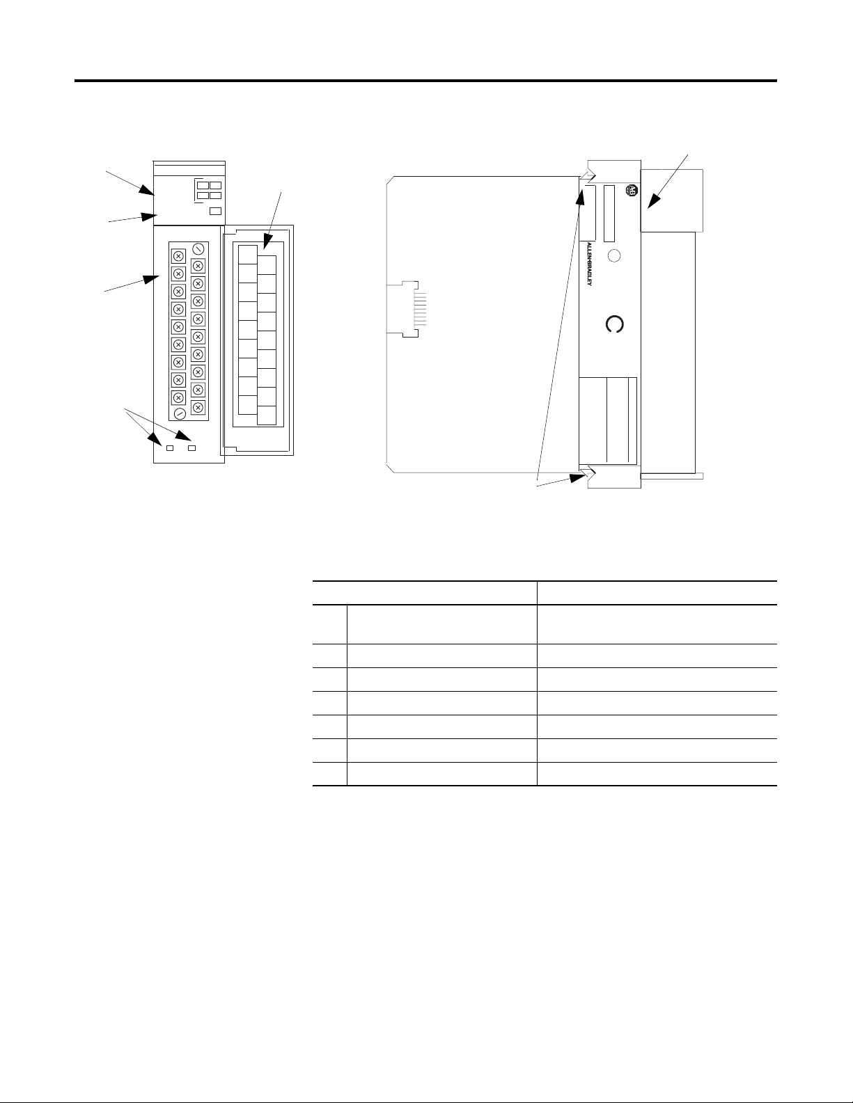
RTD Module Hardware
General Diagnostic Features
The RTD module contains diagnostic features that can be used to help
you identify the source of problems that may occur while you turn on
the power or during normal channel operation.
The power and channel diagnostics are explained in Chapter 7,
Module Diagnostics and Troubleshooting.
SLC 500
CAT
SERIAL NO.
INPUT
RTD/resistance INPUT MODULE
INPUT SIGNAL RANGES
RESIST ANCE:
CHL 1
SHIELD
SHIELD
CHL 0
RTD
SHIELD
SER
FRN
)
U
L
LISTED IND. CONT . EQ.
FOR HAZ. LOC. A196
CLASS I, GROUPS A, B, C AND D, DIV.2
OPERA TING
)
SA
RTD TYPES:
TEMPERA TURE
CODE T3C
MODULE STA
TUS
0
1
2
3
CHANNEL
STATUS
RTD/resistance
1746 NR4
NR4±xxx x
RTD
CHL 0
SENSE
CHL 1
SENSE
CHL 0
RETRN
CHL 1
RETRN
SHIELD
CHL 3
CHL 2
RTD
RTD
CHL 2
SENSE
CHL 3
SENSE
CHL 2
RETRN
CHL 3
RETRN
SHIELD
SHIELD
PLATINUM, COPPER
NICKEL, NICKEL±IRON
150 W , 500 W , 1000 W , 3000 W
1
2
3
4
5
6
7
Hardware Features
Feature Description
1 Channel Status LED Indicators
(green)
Display operating and fault status of
channels 0, 1, 2, and 3
2 Module Status LED (green) Displays module operating and fault status
3 Removable Terminal Block Provides physical connection to input devices
4 Cable Tie Slots Secure wiring from module
5 Door Label Provides terminal identification
6 Side Label (Nameplate) Provides module information
7 Self-locking Tabs Secure module in chassis slot
Publication 1746-UM008B-EN-P - December 2006
18 Overview
System Overview
The RTD module communicates to the SLC 500 processor through the
parallel backplane interface and receives +5V dc and +24V dc power
from the SLC 500 power supply through the backplane. No external
power supply is required. You may install as many RTD modules in
your system as the power supply can support.
RTD Module Configuration
Each individual channel on the RTD module can receive input signals
from two, three or four wire RTD sensors or from resistance input
devices. You configure each channel to accept either input. When
configured for RTD input types, the module converts the RTD
readings into linearized, digital temperature readings in °C or °F.
When configured for resistance inputs, the module provides a linear
resistance value in ohms.
IMPORTANT
The RTD module is designed to accept input from RTD sensors
with up to three wires. When using 4-wire RTD sensors, one of
the two lead compensation wires is not used and the 4-wire
sensor is treated like a 3-wire sensor. Lead wire compensation
is provided via the third wire.
See NR4 Wiring Considerations on page 40 for more
information.
RTD Modules
SLC Processor

Publication 1746-UM008B-EN-P - December 2006
Overview 19
System Operation
The RTD module has three operational states.
• Cycle power
• Module operation
• Error (module error and channel error)
Cycle Power
When you cycle the module’s power, the RTD module checks its
internal circuits, memory, and basic functions via hardware and
software diagnostics. During this time the module status LED indicator
remains off. If no faults are found during the diagnostics, the module
status LED indicator is on.
After the checks are complete, the RTD module waits for valid
channel configuration data from your SLC ladder logic program
(channel status LED indicators off). After configuration data is written
to one or more channel configuration words and their channel enable
bits are set by the user program, the channel status LED indicators go
on and the module continuously converts the RTD or resistance input
to a value within the range you selected for the enabled channels. The
module is now operating in its normal state.
Each time a channel is read by the module, that data value is tested by
the module for a fault condition, for example, open circuit, short
circuit, over range, and under range. If such a condition is detected, a
unique bit is set in the channel status word and the channel status
LED indicator blinks, indicating a channel error condition.
The SLC processor reads the converted RTD or resistance data from
the module at the end of the program scan or when commanded by
the ladder program. The processor and RTD module determine that
the backplane data transfer was made without error and the data is
used in your ladder program.
Module Operation
Each input channel consists of an RTD connection, which provides:
• excitation current.
• a sense connection, which detects lead-wire resistance.
• a return connection, which reads the RTD or resistance value.
Each of these analog inputs are multiplexed to one of two analog
convertors.
Publication 1746-UM008B-EN-P - December 2006
20 Overview
The A/D convertors cycle between reading the RTD or resistance
value, the lead wire resistance, and the excitation current. From these
readings, an accurate temperature or resistance is returned to the user
program.
The RTD module is isolated from the chassis backplane and chassis
ground. The isolation is limited to 500V dc. Optocouplers are used to
communicate across the isolation barrier. Channel-to-channel
common-mode isolation is limited to X 1 volt.
LED Indicator Status
The following figure shows the RTD module LED indicator panel
consisting of five LED indicators. The state of the LED indicators (for
example, off, on, or blinking) depends on the operational state of the
module.
See the LED Indicator Status table on page 21.
LED Indicators
The purpose of the LED indicators is to provide:
• Channel Status - One LED indicator for each of the four input
channels indicates if the channel is enabled, disabled, or is not
operating as configured, due to an error.
• Module Status - If OFF at any time, other than when you cycle
module power, this LED indicator indicates that non-recoverable
module errors (for example, diagnostic or operating errors) have
occurred. The LED indicator is ON if there are no module errors.
MODULE STATUS
INPUT
0 2
1 3
CHANNEL
STATUS
RTD/resistance
Publication 1746-UM008B-EN-P - December 2006
Overview 21
The status of each LED indicator, during each of the operational states
(for example, powerup, module operation and error), is depicted in
the following table.
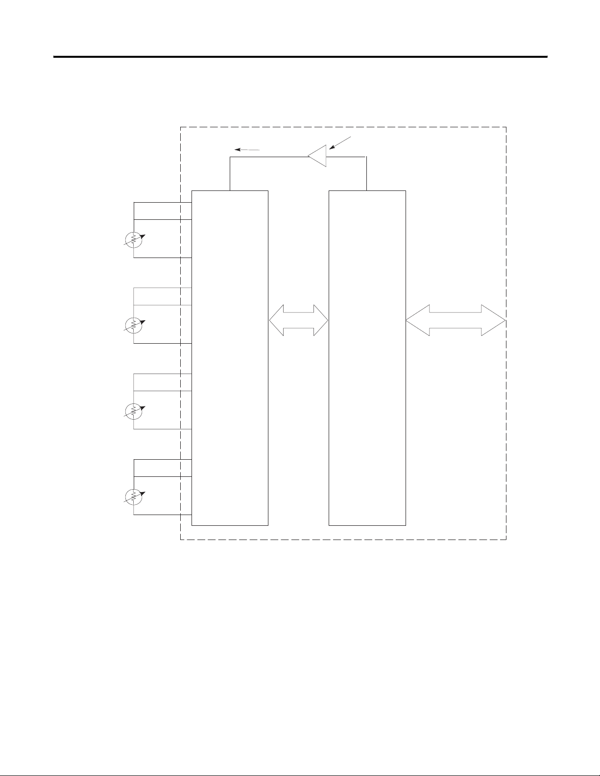
Module to Processor Communication
The RTD module communicates with the SLC processor through the
backplane of the chassis. The RTD module transfers data to and
receives data from the processor by means of an image table. The
image table consists of eight input words and eight output words.
Data transmitted from the module to the processor is called the input
image (for example, Channel Data Words and Channel Status Words).
Conversely, data transmitted from the processor to the module is
called the output image (for example, Channel Configuration Words
and Scaling Limit Words).
Details about the input and output images are found in Module
Addressing on page 52 and 53.
Communication Flow
LED Indicator Status
LED Indicator Cycle
Power
Module Operation
(No Error)
Module Error Channel
Error
Ch 0 Status
Off
(1)
(1)
Module is disabled while you cycle module power.
On/Off
(2)
(2)
Channel status LED indicator is ON if the respective channel is enabled and OFF if the channel is disabled.
Off Blinks
Ch 1 Status
Off
(1)
On/Off
(2)
Off Blinks
Ch 2 Status
Off
(1)
On/Off
(2)
Off Blinks
Ch 3 Status
Off
(1)
On/Off
(2)
Off Blinks
Mod. Status
Off
(1)
On Off On
Channel Data Words
Channel Status Words
Scaling Limit Words
Channel Configuration Words
SLC 500
Processor
1746-NR4
Input
Module
RTD/
resistance
Analog
Signals

Publication 1746-UM008B-EN-P - December 2006
22 Overview
The Channel Configuration Words (output image) contain
user-defined configuration information for the specified input channel.
This information is used by the module to configure and operate each
channel. The Channel Status Words (input image) contain status
information about the channel’s current configuration and operational
state. The input data values of the analog input channel are contained
in the Channel Data Word (input image), which is valid only when the
channel is enabled and there are no channel errors (for example,
broken sensor or overrange.)
You set the Scaling Limit Words (output image) to provide a definable
scaling range for the temperature resistance data when using the
proportional counts data type.
Image Table
Input Image
Word
Function Output
Image Word
Function
0 Channel 0 data 0 Channel 0 configuration
1 Channel 1 data 1 Channel 1 configuration
2 Channel 2 data 2 Channel 2 configuration
3 Channel 3 data 3 Channel 3 configuration
4 Channel 4 data 4 User-set Lower limit scale 0
5 Channel 5 data 5 User-set Upper limit scale 0
6 Channel 6 data 6 User-set Lower limit scale 1
7 Channel 7 data 7 User-set Upper limit scale 1

23 Publication 1746-UM008B-EN-P - December 2006
Chapter
2
Quick Start Guide
This chapter helps you get started using the RTD module. The
procedures included here assume that you have a basic understanding
of SLC 500 products.
You must:
• understand electronic process control.
• be able to interpret the ladder logic instructions for generating
the electronic signals that control your application.
Because this is a start-up guide, this chapter does not contain detailed
explanations about the procedures listed. It does, however, reference
other chapters in this book where you can get more detailed
information.
If you have any questions or are unfamiliar with the terms used or
concepts presented in the procedural steps, always read the
referenced chapters and other recommended documentation before
trying to apply the information.
This chapter:
• tells you what equipment you need.
• explains how to install and wire the module.
• shows you how to set up one channel for RTD or resistance
input.
• examines the state of the LED indicators at normal startup.
• examines the channel status word.
Required Tools and
Equipment
Have the following tools and equipment ready.
• Medium blade screwdriver
• Medium cross-head screwdriver
• RTD module (1746-NR4)
• RTD sensor or resistance input
• Appropriate cable (if needed)
• Programming software

Publication 1746-UM008B-EN-P - December 2006
24 Quick Start Guide
Procedures
Follow these procedures to get your RTD module installed and ready
to use.
Unpack the Module
Unpack the module making sure that the contents include:
• RTD module, catalog number 1746-NR4.
• Installation instructions, publication 1746-IN012.
If the contents are incomplete contact your Allen-Bradley
representative for assistance.
Determine Power Requirements
Review the requirements of your system to see that your chassis
supports placement of the RTD module.
• The fixed, 2-slot chassis supports two RTD modules.
If combining an RTD module with a different module, refer to
the module compatibility table found in chapter 3.
• For modular style systems, calculate the total load on the system
power supply using the procedure described in the SLC 500
Modular Style User Manual, publication 1747-UM011.
For more information refer to chapter 3, Install and Wire and
Appendix A, Specifications.
Publication 1746-UM008B-EN-P - December 2006
Quick Start Guide 25
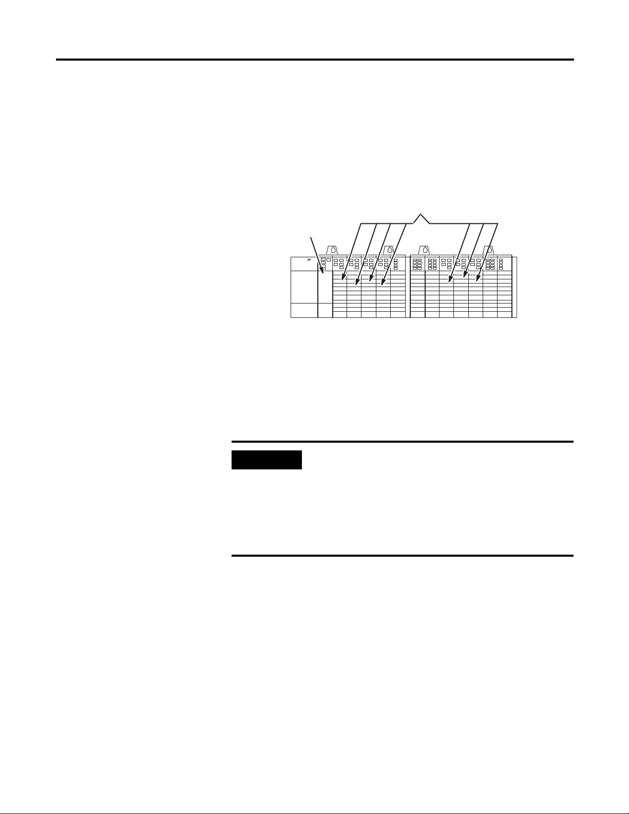
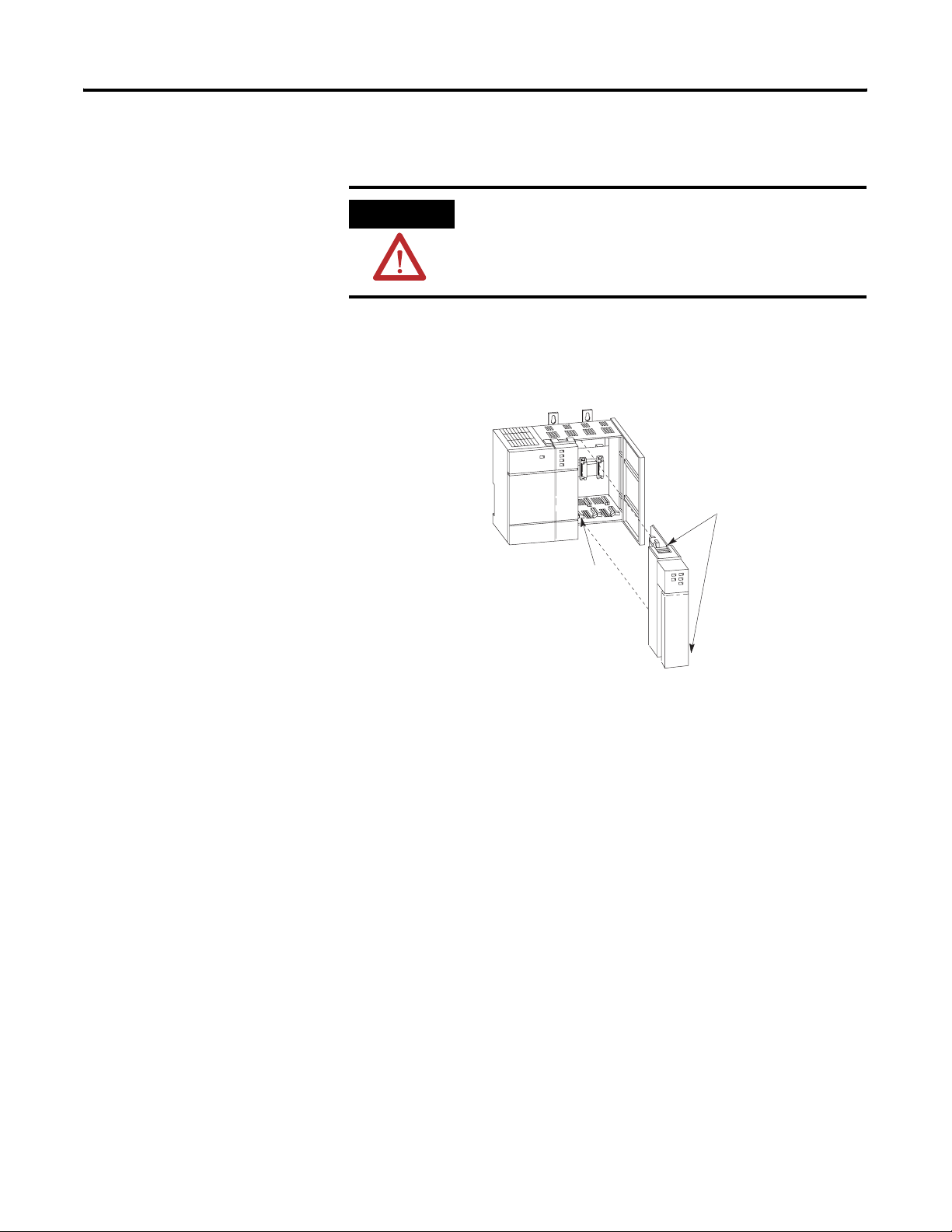
Insert the Module
Make sure system power is off; then insert the RTD module into your
1746 chassis. In this example procedure, local slot 1 is selected.
Module Insertion into Chassis
Wire the Module
Connect RTD module or potentiometer wire leads to channel 0 of the
RTD module.
See RTD Connections to Terminal Block on page 26, Two-wire
Potentiometer Connections to Terminal Block on page 27, or
Three-wire Potentiometer Connections to Terminal Block on page 28.
For more information refer to chapter 3, Install and Wire.
ATTENTION
Never install, remove, or wire modules with power applied to
the chassis or devices wired to the module.
For more information refer to chapter 3, Install and Wire.
Card Guide
Top and Bottom
Module Release(s)
Publication 1746-UM008B-EN-P - December 2006
26 Quick Start Guide
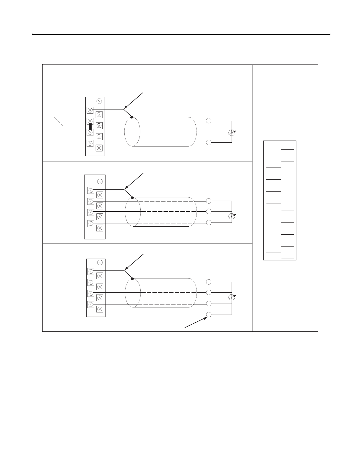
RTD Connections to Terminal Block
Chl 1
Shield
Shield
Chl 0
RT D
Shield
RT D
Chl 0
Sense
Chl 1
Sense
Chl 0
Return
Chl 1
Return
Shield
Chl 3
Chl 2
RT D
RT D
Chl 2
Sense
Chl 3
Sense
Chl 2
Return
Chl 3
Return
Shield
Shield
Terminal Pin-outs
Cable Shield
For details on wiring an RTD unit to the module, see chapter 3.
Add jumper.
Shield
Chl 0 RTD
Chl 0 Sense
Chl 0 Return
RTD
Return
RTD
Return
Belden #9501 Shielded Cable
Two Wire RTD Interconnection
Three Wire RTD Interconnection
Shield
Chl 0 RTD
Chl 0 Sense
Chl 0 Return
Four Wire RTD Interconnection
Shield
Chl 0 RTD
Chl 0 Sense
Chl 0 Return
RTD
Return
RTD
Return
Sense
Sense
RTD
Return
RTD
Return
Sense
Sense
Belden #83503 or Belden #9533 Shielded Cable
Belden #83503 or Belden #9533 Shielded Cable
Leave one sensor wire open
Cable Shield
Cable Shield
Publication 1746-UM008B-EN-P - December 2006
Quick Start Guide 27
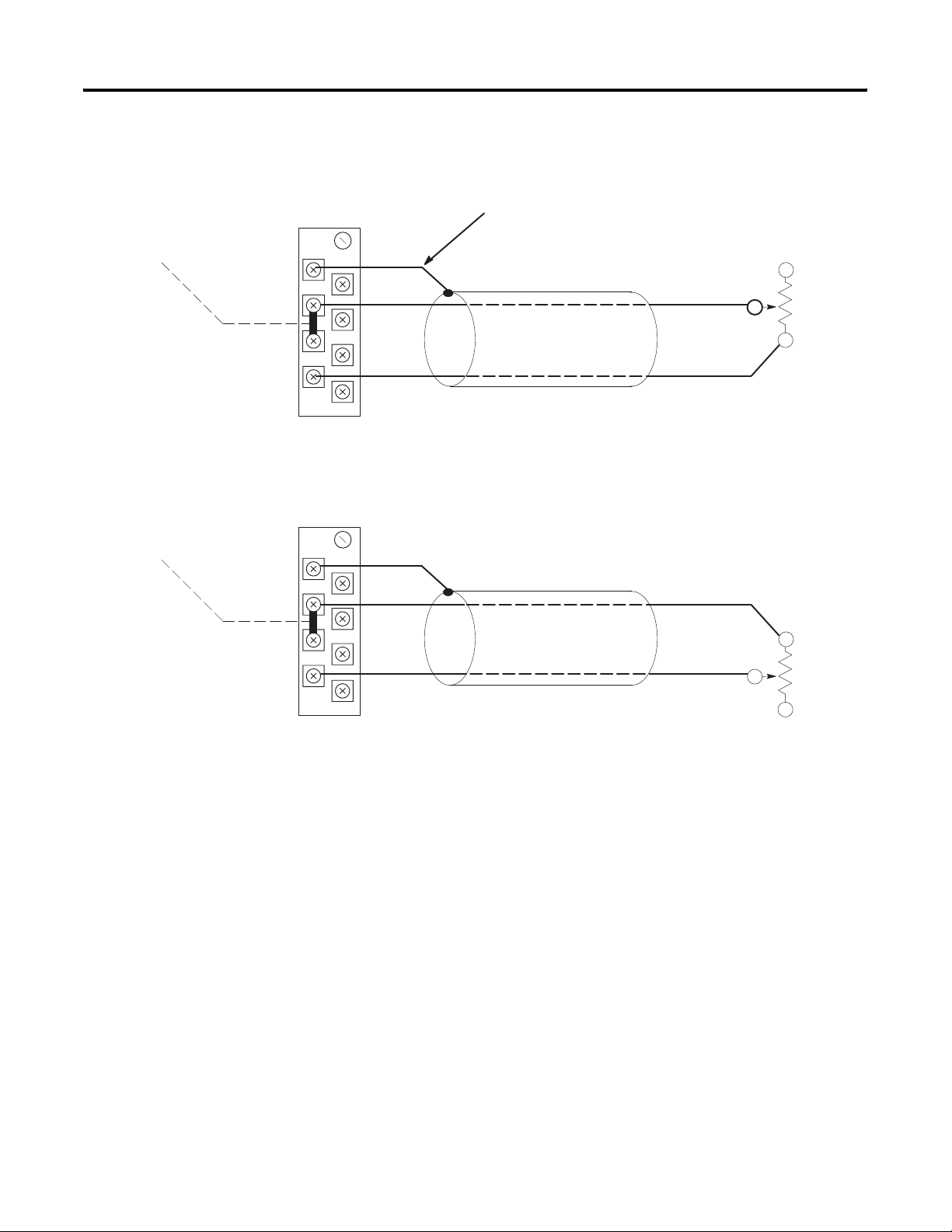
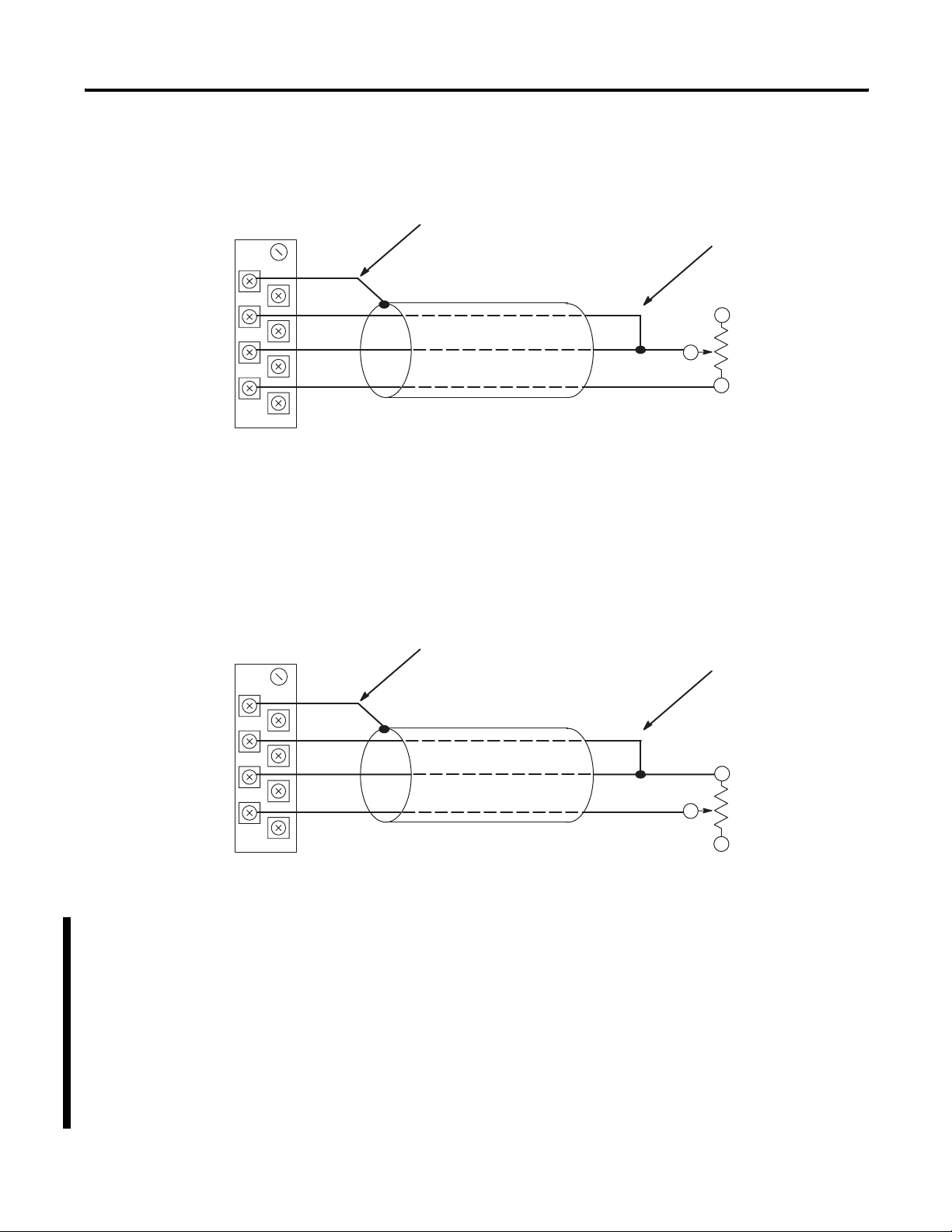
Two-wire Potentiometer Connections to Terminal Block
Add jumper.
Add jumper.
Shield
Chl 0 RTD
Chl 0 Sense
Chl 0 Return
RTD
Return
RTD
Return
Belden #9501 Shielded Cable
Cable Shield
Potentiometer
Potentiometer
Belden #9501 Shielded Cable
Potentiometer wiper arm can be connected to either the RTD or return terminal
depending on whether the user wants increasing or decreasing resistance.
Shield
Chl 0 RTD
Chl 0 Sense
Chl 0 Return
For details on wiring an RTD unit to the module, see chapter 3.
Publication 1746-UM008B-EN-P - December 2006
28 Quick Start Guide
Three-wire Potentiometer Connections to Terminal Block
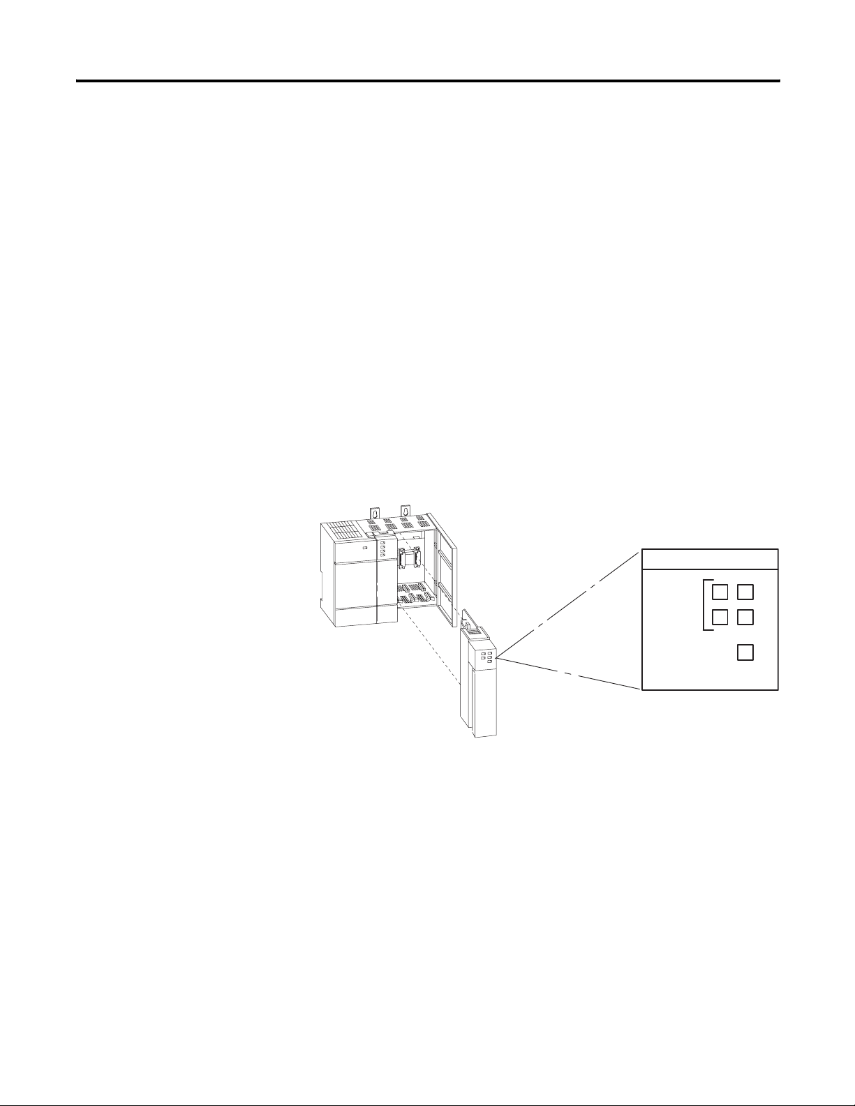
Configure Your I/O
Configure your system I/O configuration for the particular slot where
the RTD module resides (slot 1 in this example). Select the 1746-NR4
module from the list of modules, or if it is not listed in your software
version, select Other and enter the RTD module ID code (3513) at the
prompt on the I/O configuration display.
For more information refer to chapter 4, Preliminary Operating
Considerations.
For details on wiring an RTD to the module, see chapter 3.
Shield
Chl 0 RTD
Chl 0 Sense
Chl 0 Return
RTD
Return
Sense
Belden #83503 or Belden #9533 Shielded Cable
Cable Shield Run RTD unit and sense wires from module to
potentiometer terminal and tie them to one point.
Potentiometer
Potentiometer
Cable Shield
Run RTD and sense wires from module to
potentiometer terminal and tie them to one point.
Belden #83503 or Belden #9533 Shielded Cable
Shield
Chl 0 RTD
Chl 0 Sense
Chl 0 Return
RTD
Return
Sense
Potentiometer wiper arm can be connected to either the RTD or return terminal
depending on whether you want increasing or decreasing resistance.
Publication 1746-UM008B-EN-P - December 2006
Quick Start Guide 29
Configure the Module
Determine the operating parameters for channel 0. In this example,
the figure shows the channel 0 configuration word defined with all
defaults (0) except for channel enable (bit 11). The addressing reflects
the location of the module as slot 1.
For details on how to configure the module for your application, refer
to chapter 4 and chapter 5.
A configuration worksheet is included on page 132 to assist you in
channel configuration.
For more information refer to chapter 5, Channel Configuration, Data,
and Status.
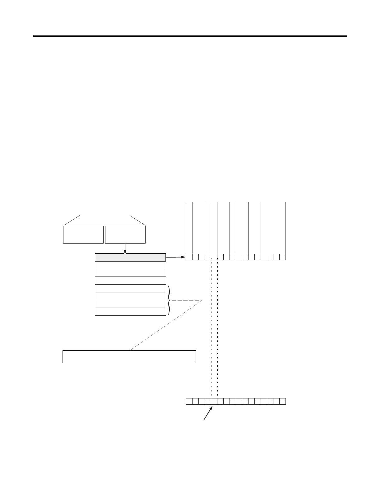
Output Image Detail
O:1.1
Channel 1 Configuration Word
Channel 2 Configuration Word
Channel 3 Configuration Word
Output Image
SLC 500 Controller
Data Files
Bit 15
Bit 0
Word 1
Word 2
Word 3
Address
O:1.0
Input Image
0
0
0
0
0
0
0
0
0
0
0
0
0
0
0
0
Channel 0 Configuration Word
Word 0
Input T ype Select
Data Format Select
Broken Input Select
Temperature Units Select
Filter Frequency Select
Channel Enable
(8 words)
0
0
0
0
1
0
0
0
0
0
0
0
0
0
0
0
Default Settings
New Setting
Set this bit (11) to enable channel. Address = O:1.0/11
• 100 Platinum R TD (385)
• Engineering
Units x 1 (0.1
˚/ step)
• Broken Input (set data word to zero)
• Degrees Celsius ( ˚C)
• 10
Hz Filter Frequency
• Channel Disabled
• 2.0 mA Excitation Current
• Module Defined Scaling
O:1.2
O:1.3
User-set Lower Scale Limit Range 0
Word 4
O:1.4
User-set Upper Scale Limit Range 0
Word 5
O:1.5
Word 6
O:1.6
Word 7
O:1.7
Bit 15 Bit 0
Excitation Current Select
Scaling Select *
Not Defined
If proportional counts data format is used, then output words 4…7
can be used to define a user-set scaling range for each channel.
* Scaling Select bits apply to proportional counts mode.
Limit Scale W ords are only used if scaling select = 01
or
10 and data format = 11.
User-set Upper Scale Limit Range 1
User-set Lower Scale Limit Range 1
Publication 1746-UM008B-EN-P - December 2006
30 Quick Start Guide
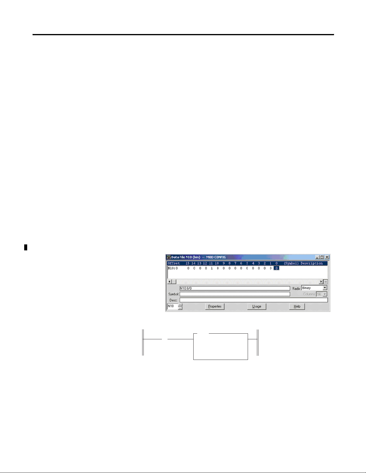
Program the Configuration
Follow these steps to complete the programming necessary to
establish the new configuration word setting in the previous step.
1. Create integer file N10 using the memory map function.
Integer file N10 should contain one element for each channel
used. For this example we only need one, N10:0.
2. Enter the configuration parameters for channel 0 into integer
N10:0.
In this example, all the bits of N10:0 are zero except for the
channel enable (N10:0/11).
3. Program an instruction in your ladder logic to copy the contents
of N10:0 to output word O:1.0.
See Output Image Detail on page 28.
For more information refer to chapter 6, Ladder Programming
Examples and chapter 8, Application Examples.
Initial Configuration Word Setting
Dest # O:1.0
Length 1
On power±up, the first pass bit
(S:1/15) is set for one scan, enabling
the COPY instruction that transfers a
one to bit 11 of channel configuration
word 0. This enables channel 0,
which directs the RTD module to sca
n
channel 0 and to present the analog
data to the SLC processor.
] [
COP
COPY FILE
Source # N10:0
First Pass Bit
S:1
15
Loading...