


 Loading...
SLC™ 500 4-Channel Thermocouple/mV Input Module
(Catalog Number 1746-NT4,
Series B)
User Manual
Important User Information |
Solid state equipment has operational characteristics differing from those of |
||||||
|
|||||||
|
electromechanical equipment. Safety Guidelines for the Application, |
||||||
|
Installation and Maintenance of Solid State Controls (Publication SGI-1.1 |
||||||
|
available from your local Rockwell Automation sales office or online at |
||||||
|
http://www.ab.com/manuals/gi) describes some important differences |
||||||
|
between solid state equipment and hard-wired electromechanical devices. |
||||||
|
Because of this difference, and also because of the wide variety of uses for |
||||||
|
solid state equipment, all persons responsible for applying this equipment |
||||||
|
must satisfy themselves that each intended application of this equipment is |
||||||
|
acceptable. |
|
|
||||
|
In no event will Rockwell Automation, Inc. be responsible or liable for |
||||||
|
indirect or consequential damages resulting from the use or application of |
||||||
|
this equipment. |
|
|
||||
|
The examples and diagrams in this manual are included solely for illustrative |
||||||
|
purposes. Because of the many variables and requirements associated with |
||||||
|
any particular installation, Rockwell Automation, Inc. cannot assume |
||||||
|
responsibility or liability for actual use based on the examples and diagrams. |
||||||
|
No patent liability is assumed by Rockwell Automation, Inc. with respect to |
||||||
|
use of information, circuits, equipment, or software described in this manual. |
||||||
|
Reproduction of the contents of this manual, in whole or in part, without |
||||||
|
written permission of Rockwell Automation, Inc. is prohibited. |
||||||
|
Throughout this manual we use notes to make you aware of safety |
||||||
|
considerations. |
|
|
||||
|
|
|
|
|
|
|
|
|
|
|
|
|
|
|
Identifies information about practices or circumstances |
|
WARNING |
||||||
|
|
that can cause an explosion in a hazardous environment, |
|||||
|
|
|
|
|
|
|
|
|
|
|
|
|
|
|
which may lead to personal injury or death, property |
|
|
|
|
|
|
|
damage, or economic loss. |
|
|
|
|
|
|
|
|
|
|
|
|
|
|
|
|
|
|
|
|
|
|
|
|
|
|
|
|
|
|
|
|
|
|
|
|
|
|
|
Identifies information that is critical for successful |
|
IMPORTANT |
|
|||||
|
|
application and understanding of the product. |
|||||
|
|
|
|
|
|
|
|
|
|
|
|
|
|
|
|
|
|
|
|
|
|
|
|
|
|
|
|
|
|
|
Identifies information about practices or circumstances |
|
ATTENTION |
|
|||||
|
|
that can lead to personal injury or death, property |
|||||
|
|
|
|
|
|
|
|
|
|
|
|
|
|
|
damage, or economic loss. Attentions help you: |
|
|
|
|
|
|
|
• identify a hazard |
|
|
|
|
|
|
|
• avoid a hazard |
|
|
|
|
|
|
|
• recognize the consequence |
|
|
|
|
|
|
|
|
|
|
|
|
|
|
|
|
|
|
|
|
|
|
|
Labels may be located on or inside the drive to alert |
|
SHOCK HAZARD |
|
|||||
|
|
|
|
|
|
|
people that dangerous voltage may be present. |
|
|
|
|
|
|
|
|
|
|
|
|
|
|
|
|
|
|
|
|
|
|
|
|
|
|
|
|
|
|
|
|
|
|
|
|
|
|
|
|
BURN HAZARD |
Labels may be located on or inside the drive to alert |
|
people that surfaces may be dangerous temperatures. |

Summary of Changes
The information below summarizes the changes to this manual since the last printing.
To help you find new and updated information in this release of the manual, we have included change bars as shown to the right of this paragraph.
For information on: |
See page: |
|
|
Changes to the SLC™ 500 Thermocouple/mV Input Module. |
throughout manual |
|
|
Using RSLogix™ 500 to configure the NT4 module. |
2-4, 5-2, 6-1, and Appendix |
|
E |
|
|
Maintaining the ambient temperature surrounding the SLC |
A-2 |
500 above 3°C (37.4°F). |
|
|
|
Publication 1746-UM007C-EN-P - July 2004

2 Summary of Changes
Publication 1746-UM007C-EN-P - July 2004

Table of Contents
Preface
|
Who Should Use this Manual. . . . . . . . . . . . . . . . . . . . . . . |
P-1 |
|
Purpose of this Manual . . . . . . . . . . . . . . . . . . . . . . . . . . . |
P-1 |
|
Related Documentation . . . . . . . . . . . . . . . . . . . . . . . . |
P-2 |
|
Your Questions or Comments on this Manual . . . . . . . . |
P-3 |
|
Common Techniques Used in this Manual . . . . . . . . . . . . . |
P-3 |
|
Chapter 1 |
|
Overview |
General Description . . . . . . . . . . . . . . . . . . . . . . . . . . . . . |
1-1 |
|
Hardware Features. . . . . . . . . . . . . . . . . . . . . . . . . . . . |
1-2 |
|
General Diagnostic Features . . . . . . . . . . . . . . . . . . . . . |
1-3 |
|
System Overview . . . . . . . . . . . . . . . . . . . . . . . . . . . . . . . |
1-3 |
|
System Operation . . . . . . . . . . . . . . . . . . . . . . . . . . . . |
1-4 |
|
Module Operation . . . . . . . . . . . . . . . . . . . . . . . . . . . . |
1-5 |
|
Thermocouple Compatibility . . . . . . . . . . . . . . . . . . . . |
1-5 |
|
Linear Millivolt Device Compatibility. . . . . . . . . . . . . . . |
1-7 |
|
Chapter 2 |
|
Quick Start for Experienced Users |
Required Tools and Equipment . . . . . . . . . . . . . . . . . . . . . |
2-1 |
|
Installation Procedures . . . . . . . . . . . . . . . . . . . . . . . . . . . |
2-2 |
|
Chapter 3 |
|
Installation and Wiring |
Compliance to European Union Directives . . . . . . . . . . . . . |
3-1 |
|
EMC Directive . . . . . . . . . . . . . . . . . . . . . . . . . . . . . . . |
3-1 |
|
Electrostatic Discharge. . . . . . . . . . . . . . . . . . . . . . . . . . . . |
3-2 |
|
NT4 Power Requirements . . . . . . . . . . . . . . . . . . . . . . . . . |
3-2 |
|
Module Location in Chassis . . . . . . . . . . . . . . . . . . . . . . . . |
3-3 |
|
Fixed Expansion Chassis Considerations . . . . . . . . . . . . |
3-3 |
|
General Considerations . . . . . . . . . . . . . . . . . . . . . . . . |
3-5 |
|
Module Installation and Removal . . . . . . . . . . . . . . . . . . . . |
3-5 |
|
Terminal Block Removal . . . . . . . . . . . . . . . . . . . . . . . |
3-6 |
|
Module Installation Procedure . . . . . . . . . . . . . . . . . . . |
3-6 |
|
Module Removal Procedure . . . . . . . . . . . . . . . . . . . . . |
3-7 |
|
Terminal Wiring . . . . . . . . . . . . . . . . . . . . . . . . . . . . . . . . |
3-7 |
|
Wiring Considerations . . . . . . . . . . . . . . . . . . . . . . . . . |
3-8 |
|
Wiring Input Devices to the NT4 . . . . . . . . . . . . . . . . . |
3-11 |
|
Cold Junction Compensation (CJC) . . . . . . . . . . . . . . . . |
3-12 |
|
Thermocouple Calibration . . . . . . . . . . . . . . . . . . . . . . . . . |
3-13 |
|
Chapter 4 |
|
Preliminary Operating |
Module ID Code . . . . . . . . . . . . . . . . . . . . . . . . . . . . . . . . |
4-1 |
Considerations |
Module Addressing . . . . . . . . . . . . . . . . . . . . . . . . . . . . . . |
4-2 |
|
Output Image-Configuration Words . . . . . . . . . . . . . . . |
4-2 |
|
Input Image-Data Words and Status Words . . . . . . . . . . |
4-3 |
|
Channel Filter Frequency Selection . . . . . . . . . . . . . . . . . . |
4-4 |
Publication 1746-UM007C-EN-P - July 2004

Table of Contents |
ii |
|
|
Channel Configuration, Data, and
Status
Ladder Programming Examples
Effective Resolution . . . . . . . . . . . . . . . . . . . . . . . . . . . 4-4 Channel Cut-Off Frequency . . . . . . . . . . . . . . . . . . . . . 4-5 Channel Step Response . . . . . . . . . . . . . . . . . . . . . . . . 4-6 Update Time. . . . . . . . . . . . . . . . . . . . . . . . . . . . . . . . . . . 4-7 Update Time Calculation Example . . . . . . . . . . . . . . . . 4-8 Channel Turn-On, Turn-Off, and Reconfiguration Times . . . 4-9 Response to Slot Disabling . . . . . . . . . . . . . . . . . . . . . . . . 4-10 Input Response . . . . . . . . . . . . . . . . . . . . . . . . . . . . . . 4-10 Output Response . . . . . . . . . . . . . . . . . . . . . . . . . . . . . 4-10
Chapter 5
Channel Configuration . . . . . . . . . . . . . . . . . . . . . . . . . . . 5-1 Channel Configuration Procedure . . . . . . . . . . . . . . . . . . . 5-2 Select Input Type (Bits 0-3) . . . . . . . . . . . . . . . . . . . . . 5-5 Select Data Format (Bits 4 and 5) . . . . . . . . . . . . . . . . . 5-5 Using Scaled-for-PID and Proportional Counts . . . . . . . 5-6 Scaling Examples . . . . . . . . . . . . . . . . . . . . . . . . . . . . . 5-7 Select Open Circuit State (Bits 6 and 7). . . . . . . . . . . . . 5-10 Select Temperature Units (Bit 8) . . . . . . . . . . . . . . . . . . 5-11 Select Channel Filter Frequency (Bits 9 and 10). . . . . . . 5-11 Select Channel Enable (Bit 11) . . . . . . . . . . . . . . . . . . . 5-12 Unused Bits (Bits 12-15). . . . . . . . . . . . . . . . . . . . . . . . 5-12 Channel Data Word. . . . . . . . . . . . . . . . . . . . . . . . . . . . . . 5-12 Channel Status Checking . . . . . . . . . . . . . . . . . . . . . . . . . . 5-13 Status Conditions . . . . . . . . . . . . . . . . . . . . . . . . . . . . . . . 5-15 Input Type Status (Bits 0-3) . . . . . . . . . . . . . . . . . . . . . 5-15 Data Format Type Status (Bits 4 and 5) . . . . . . . . . . . . . 5-15 Open Circuit Type Status (Bits 6 and 7) . . . . . . . . . . . . 5-15 Temperature Units Type Status (Bit 8). . . . . . . . . . . . . . 5-16 Channel Filter Frequency (Bits 9 and 10) . . . . . . . . . . . 5-16 Channel Status (Bit 11). . . . . . . . . . . . . . . . . . . . . . . . . 5-16 Open-Circuit Error (Bit 12) . . . . . . . . . . . . . . . . . . . . . . 5-16 Under-Range Error (Bit 13). . . . . . . . . . . . . . . . . . . . . . 5-16 Over-Range Error (Bit 14). . . . . . . . . . . . . . . . . . . . . . . 5-17 Configuration Error (Bit 15) . . . . . . . . . . . . . . . . . . . . . 5-17
Chapter 6
Initial Programming. . . . . . . . . . . . . . . . . . . . . . . . . . . . . . 6-1 Procedure . . . . . . . . . . . . . . . . . . . . . . . . . . . . . . . . . . 6-2 Dynamic Programming . . . . . . . . . . . . . . . . . . . . . . . . . . . 6-3 Verifying Channel Configuration Changes . . . . . . . . . . . . . 6-4 Interfacing to the PID Instruction. . . . . . . . . . . . . . . . . . . . 6-5 Monitoring Channel Status Bits . . . . . . . . . . . . . . . . . . . . . 6-6 Invoking Autocalibration . . . . . . . . . . . . . . . . . . . . . . . . . . 6-7
Publication 1746-UM007C-EN-P - July 2004

Table of Contents iii
Chapter 7
Module Diagnostics and |
Module Operation vs Channel Operation . . . . . . . . . . . . . . |
7-1 |
Troubleshooting |
Power-up Diagnostics . . . . . . . . . . . . . . . . . . . . . . . . . . . . |
7-1 |
|
Channel Diagnostics . . . . . . . . . . . . . . . . . . . . . . . . . . . . . |
7-2 |
|
LED Indicators . . . . . . . . . . . . . . . . . . . . . . . . . . . . . . . . . |
7-3 |
|
Channel Status LEDs (Green) . . . . . . . . . . . . . . . . . . . . |
7-4 |
|
Invalid Channel Configuration . . . . . . . . . . . . . . . . . . . |
7-4 |
|
Open Circuit Detection . . . . . . . . . . . . . . . . . . . . . . . . |
7-4 |
|
Out-Of-Range Detection. . . . . . . . . . . . . . . . . . . . . . . . |
7-5 |
|
Module Status LED (Green) . . . . . . . . . . . . . . . . . . . . . |
7-5 |
|
Troubleshooting Flowchart . . . . . . . . . . . . . . . . . . . . . . . . |
7-6 |
|
Replacement Parts. . . . . . . . . . . . . . . . . . . . . . . . . . . . . . . |
7-7 |
|
Contacting Rockwell Automation . . . . . . . . . . . . . . . . . . . . |
7-7 |
|
Chapter 8 |
|
Application Examples |
Basic Example . . . . . . . . . . . . . . . . . . . . . . . . . . . . . . . . . |
8-1 |
|
Application Setup (Display a Temperature) . . . . . . . . . |
8-1 |
|
Channel Configuration . . . . . . . . . . . . . . . . . . . . . . . . . |
8-2 |
|
Supplementary Example . . . . . . . . . . . . . . . . . . . . . . . . . . |
8-4 |
|
Application Setup (Four Channels °C - °F) . . . . . . . . . . |
8-4 |
|
Device Configuration . . . . . . . . . . . . . . . . . . . . . . . . . . |
8-4 |
|
Channel Configuration . . . . . . . . . . . . . . . . . . . . . . . . . |
8-5 |
|
Program Setup and Operation Summary . . . . . . . . . . . . |
8-7 |
|
Program Listing . . . . . . . . . . . . . . . . . . . . . . . . . . . . . . |
8-7 |
|
Appendix A |
|
Specifications |
Electrical Specifications . . . . . . . . . . . . . . . . . . . . . . . . . . . |
A-1 |
|
Physical Specifications. . . . . . . . . . . . . . . . . . . . . . . . . . . . |
A-2 |
|
Environmental Specifications . . . . . . . . . . . . . . . . . . . . . . . |
A-2 |
|
Input Specifications. . . . . . . . . . . . . . . . . . . . . . . . . . . . . . |
A-3 |
|
1746-NT4 Module Accuracy . . . . . . . . . . . . . . . . . . . . . |
A-4 |
|
Input Resolution per Thermocouple Type at Each Filter |
|
|
Frequency . . . . . . . . . . . . . . . . . . . . . . . . . . . . . . . . . . . . |
A-4 |
|
Appendix B |
|
NT4 Configuration Worksheet |
Channel Configuration Procedure . . . . . . . . . . . . . . . . . . . |
B-1 |
|
Channel Configuration Worksheet . . . . . . . . . . . . . . . . . . . |
B-4 |
|
Appendix C |
|
Thermocouple Restrictions |
J Type Thermocouple . . . . . . . . . . . . . . . . . . . . . . . . . . . . |
C-1 |
|
(Iron vs. Copper-Nickel <Constantan>) . . . . . . . . . . . . . |
C-1 |
|
K Type Thermocouple . . . . . . . . . . . . . . . . . . . . . . . . . . . |
C-2 |
|
(NIckel-Chromium vs. Nickel-Aluminum) . . . . . . . . . . . |
C-2 |
|
T Type Thermocouple. . . . . . . . . . . . . . . . . . . . . . . . . . . . |
C-3 |
Publication 1746-UM007C-EN-P - July 2004

Table of Contents |
iv |
|
|
(Copper vs. Copper-Nickel <Constantan>) . . . . . . . . . . C-3 E Type Thermocouple. . . . . . . . . . . . . . . . . . . . . . . . . . . . C-4 (Nickel-Chromium vs. Copper-Nickel <Constantan>) . . . C-4 S and R Type Thermocouples . . . . . . . . . . . . . . . . . . . . . . C-5
S (Platinum-10% Rhodium vs. Platinum)
R (Platinum-13% Rhodium vs. Platinum) . . . . . . . . . . . C-5
Appendix D
Thermocouple Types
Appendix E
Configuring the 1746-NT4 Module with RSLogix 500
Glossary
Index
Publication 1746-UM007C-EN-P - July 2004

Preface
Who Should Use this Manual
Purpose of this Manual
Read this preface to familiarize yourself with the rest of the manual. The preface includes:
•Who Should Use this Manual
•Purpose of this Manual
•Common Techniques Used in this Manual
Use this manual if you are responsible for designing, installing, programming, or troubleshooting control systems that use SLC 500 4-Channel Thermocouple/mV Input Module.
You should have a basic understanding of electrical circuitry and familiarity with relay logic. If you do not, obtain the proper training before using this product.
This manual describes the procedures you use to install, wire, and troubleshoot your 4-channel thermocouple/mV module. This manual:
•explains how to install and wire your module
•gives you an overview of the SLC 500 programmable controller system
Refer to your programming software user documentation for more information on programming your SLC 500 programmable controller.
Publication 1746-UM007C-EN-P - July 2004

2 Preface
Related Documentation
The following documents contain additional information concerning
Rockwell Automation products. To obtain a copy, contact your local
Rockwell Automation office or distributor.
|
|
For |
Read this Document |
Document Number |
|
|
|
|
|
|
|
In-depth information on the SLC Instruction Set. |
SLC 500 Instruction Set Reference Manual |
1747-RM001 |
|
|
|
|
|
|
|
A description on how to install and use your Modular SLC 500 |
SLC 500 Modular Hardware Style User |
1747-UM011 |
|
|
|||
|
|
programmable controller. |
Manual |
|
|
|
|
|
|
|
|
A description on how to install and use your Fixed SLC 500 |
Installation & Operation Manual for Fixed |
1747-6.21 |
|
|
programmable controller. |
Hardware Style Programmable Controllers |
|
|
|
|
|
|
|
|
A description on how to install the SLC 500 4-Channel |
SLC 500 4-Channel Thermocouple/mV |
1746-IN010 |
|
|
Thermocouple/mV input module |
Module Installation Instructions |
|
|
|
|
|
|
|
|
Information on reducing electrical noise. |
System Design for Control of Electrical |
GMC-RM001 |
|
|
|
Noise |
|
|
|
|
|
|
|
|
In-depth information on grounding and wiring Allen-Bradley® |
Allen-Bradley Programmable Controller |
1770-4.1 |
|
|
programmable controllers. |
Grounding and Wiring Guidelines |
|
|
|
|
|
|
|
|
A description of important differences between solid-state |
Application Considerations for Solid-State |
SGI-1.1 |
|
|
programmable controller products and hard-wired electromechanical |
Controls |
|
|
|
devices. |
|
|
|
|
|
|
|
|
|
An article on wire sizes and types for grounding electrical |
National Electrical Code - Published by the National Fire Protection |
|
|
|
equipment. |
Association of Boston, MA. |
|
|
|
|
|
|
|
|
A glossary of industrial automation terms and abbreviations. |
Allen-Bradley Industrial Automation |
AG-7.1 |
|
|
|
Glossary |
|
|
|
|
|
|
Publication 1746-UM007C-EN-P - July 2004
Preface 3
If you would like a manual, you can:
•download an electronic version from the internet at:
–www.theautomationbookstore.com
–http://www.ab.com/manuals
•order a printed manual by:
–contacting your local distributor or Rockwell Automation representative
–visiting www.theautomationbookstore.com
–calling 1.800.963.9548 (USA/Canada) or 001.330.725.1574 (Outside USA/Canada)
Common Techniques Used in this Manual
Your Questions or Comments on this Manual
If you find a problem with this manual, or you have any suggestions for how this manual could be made more useful to you, please contact us at the address below:
Rockwell Automation
Automation Control and Information Group
Technical Communication, Dept. A602V
P.O. Box 2086
Milwaukee, WI 53201-2086
The following conventions are used throughout this manual:
•Bulleted lists such as this one provide information, not procedural steps.
•Numbered lists provide sequential steps or hierarchical information.
•Italic type is used for emphasis.
Publication 1746-UM007C-EN-P - July 2004

4 Preface
Publication 1746-UM007C-EN-P - July 2004

Chapter 1
Overview
General Description
This chapter describes the thermocouple/millivolt module and explains how the SLC controller gathers thermocouple or millivolt initiated analog input from the module. This chapter includes:
•General Description
•System Overview
The thermocouple/mV module receives and stores digitally converted thermocouple and/or millivolt (mV) analog data into its image table for retrieval by all fixed and modular SLC 500 processors. The module supports connections from any combination of up to four thermocouple or mV analog sensors.
The following tables define thermocouple types and their associated full scale temperature ranges and also list the millivolt analog input signal ranges that each 1746-NT4 channel will support. To determine the practical temperature range your thermocouple supports, refer to the specifications in Appendix A.
Type |
°C Temperature Range |
|
°F Temperature Range |
|
|
|
|
J |
-210° to 760° |
|
-346° to 1400° |
|
|
|
|
K |
-270° to 1370° |
|
-454° to 2498° |
|
|
|
|
T |
-270° to 400° |
|
-454° to 752° |
|
|
|
|
B |
300° to 1820° |
|
572° to 3308° |
|
|
|
|
E |
-270° to 1000° |
|
-454° to 1832° |
|
|
|
|
R |
0° to 1768° |
|
32° to 3214° |
|
|
|
|
S |
0° to 1768° |
|
32° to 3214° |
|
|
|
|
N |
0° to 1300° |
|
32° to 2372° |
|
|
|
|
CJC Sensor |
0° to 85° |
|
32° to 185° |
|
|
|
|
|
|
||
Millivolt Input Type |
Range |
||
|
|
|
|
±50 mV |
|
-50 mV dc to +50 mV dc |
|
|
|
|
|
±100 mV |
|
-100 mV dc to +100 mV dc |
|
|
|
|
|
Each input channel is individually configurable for a specific input device and provides open-circuit, over-range, and under-range detection and indication.
Publication 1746-UM007C-EN-P - July 2004
1-2 Overview
Channel Status
LEDs (Green)
Module Status
LED (Green)
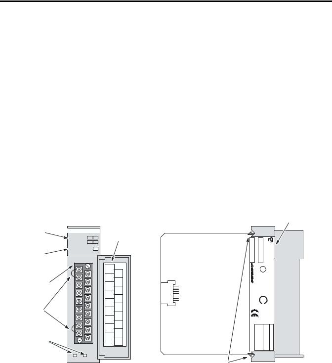
Removable
Terminal Block
CJC Sensors
Cable Tie Slots
Hardware Features
The thermocouple module fits into any single-slot, except the processor slot (0), in either an SLC 500 modular system or an SLC 500 fixed system expansion chassis (1746-A2). It is a Class 1 module (uses 8 input words and 8 output words). It interfaces to thermocouple types J, K, T, E, R, S, B, and N, and supports direct ±50 mV and ±100 mV analog input signals.
The module requires the use of Block Transfer in a remote configuration.
The module contains a removable terminal block providing connection for four thermocouple and/or analog input devices. There are also two, cold-junction compensation (CJC) sensors used to compensate for offset voltages introduced into the input signal as a result of the cold-junction, i.e., where the thermocouple wires connect to the module wiring terminal. There are no output channels on the module. Module configuration is done via the user program. There are no DIP switches.
INPUT |
|
|
|
|
|
Door Label |
|
|
|
|
|
|
|
|
|
CHANNEL |
|
0 |
|
2 |
|
||
|
|
|
|
||||
STATUS |
|
1 |
|
3 |
|
|
|
|
|
|
|
|
|||
MODULE STATUS
THERMOCOUPLE/mV |
|
CJC A+ |
|
Do Not |
|
Remove |
CHL0+ |
CJC A_ |
|
Do Not |
CHL0 _ |
Remove |
|
SHIELD |
|
|
CHL1+ |
SHIELD |
|
|
CHL1_ |
SHIELD |
|
|
CHL2+ |
SHIELD |
|
|
CHL2_ |
SHIELD |
|
CJC B_ |
CHL3+ |
|
|
Do Not |
CHL3 _ |
Remove |
|
CJC B+ |
|
Do Not |
|
Remove |
ANLG |
|
COM |
Side Label
x xxx-NT4 |
SERIAL |
1746 |
CAT |
MODULE INPUT THERMOCOUPLE/mV |
500 SLC |
|
.NO |
NT4 |
|
||||
FRN |
® |
SER |
||||
2.DIV D, AND C B, A, GROUPS I, CLASS |
U |
|||||
|
||||||
SA .EQ CONT. .IND LISTED L A196 .LOC .HAZ FOR |
||||||
|
|
OPERATING TEMPERATURE ® T3C CODE |
|
|
||
USA IN MADE 1M FAC |
_ _ |
|
|
|
||
+100mVDC to 100mVDC |
TAGE:VOL +50mVDC to 50mVDC |
N B, S, R, E, T, K, J, |
TYPES:THERMOCOUPLE |
RANGES SIGNAL INPUT |
||
Self-Locking Tabs
Publication 1746-UM007C-EN-P - July 2004

Overview 1-3
System Overview
Hardware |
Function |
|
|
Channel Status LED |
Display operating and fault status of |
Indicators |
channels 0, 1, 2, and 3 |
|
|
Module Status LED |
Displays module operating and fault status |
|
|
Side Label (Nameplate) |
Provides module information |
|
|
Removable Terminal Block |
Provides physical connection to input devices. |
|
It is color coded green. |
|
|
Door Label |
Permits easy terminal identification |
|
|
Cable Tie Slots |
Secure and route wiring from module |
|
|
Self-Locking Tabs |
Secure module in chassis slot |
|
|
General Diagnostic Features
The thermocouple/mV module contains diagnostic features that can help you identify the source of problems that may occur during power-up or during normal channel operation. These power-up and channel diagnostics are explained in chapter 7, Module Diagnostics and Troubleshooting.
The thermocouple module communicates to the SLC 500 processor through the parallel backplane interface and receives +5V dc and +24V dc power from the SLC 500 power supply through the backplane. No external power supply is required. You may install as many thermocouple modules in your system as the power supply can support.
SLC Processor |
|
|
|
|
Thermocouple Modules |
|||||||||||
|
|
|
|
|
|
|
|
|
|
|
|
|
|
|
|
|
|
|
|
|
|
|
|
|
|
|
|
|
|
|
|
|
|
|
|
|
|
|
|
|
|
|
|
|
|
|
|
|
|
|
|
|
|
|
|
|
|
|
|
|
|
|
|
|
|
|
|
|
|
|
|
|
|
|
|
|
|
|
|
|
|
|
|
|
|
|
|
|
|
|
|
|
|
|
|
|
|
|
|
|
|
|
|
|
|
|
|
|
|
|
|
|
|
|
|
|
|
|
|
|
|
|
|
|
|
|
|
|
|
|
|
|
|
|
|
|
|
|
|
|
|
|
|
|
|
|
|
|
|
|
|
|
|
|
|
|
|
|
|
|
|
|
|
|
|
|
|
|
|
|
|
|
|
|
|
|
|
|
|
|
|
|
|
|
|
|
|
|
|
|
|
|
|
|
|
|
|
|
|
|
|
|
|
Publication 1746-UM007C-EN-P - July 2004

1-4 Overview
Each individual channel on the thermocouple module can receive input signals from thermocouple sensors or mV analog input devices. You configure each channel to accept either input. When configured for thermocouple input types, the thermocouple module converts the analog input voltages into cold-junction compensated and linearized, digital temperature readings. The 1746-NT4 uses the National Bureau of Standards (NBS) Monograph 125 and 161 based on IPTS-68 for thermocouple linearization.
When configured for millivolt analog inputs, the module converts the analog values directly into digital values. The module assumes that the mV input signal is already linear.
System Operation
At power-up, the thermocouple module performs a check of its internal circuits, memory, and basic functions. During this time the module status LED remains off. If no faults are found during the power-up diagnostics, the module status LED is turned on.
|
|
Channel Data Word |
|
|
Thermocouple |
ChannelStatus Word |
|
|
SLC 500 |
||
Thermocouple or mV |
Input |
||
Processor |
|||
Analog Signals |
Module |
||
|
|||
|
|
Channel Configuration Word |
After power-up checks are complete, the thermocouple module waits for valid channel configuration data from your SLC ladder logic program (channel status LEDs off). After configuration data is written to one or more channel configuration words and their channel enable status bits are set, the channel status LEDs go on and the thermocouple module continuously converts the thermocouple or millivolt input to a value within the range you selected for the enabled channels.
Each time a channel is read by the module, that data value is tested by the module for a fault condition, i.e. open circuit, over range, and under range. If such a condition is detected, a unique bit is set in the channel status word and the channel status LED blinks.
The SLC processor reads the converted thermocouple or millivolt data from the module at the end of the program scan, or when commanded by the ladder program. The processor and thermocouple module determine that the backplane data transfer was made without error, and the data is used in your ladder program.
Publication 1746-UM007C-EN-P - July 2004

Overview 1-5
Module Operation
The thermocouple module input circuitry consists of four differential analog inputs multiplexed into a single analog-to-digital (A/D) convertor. The mux circuitry also continuously samples the CJC A and CJC B sensors and compensates for temperature changes at the cold junction (terminal block). The figure on the following page shows a block diagram for the analog input circuitry.
The A/D convertor reads the selected input signal and converts it to a digital value. The multiplexer sequentially switches each input channel to the module’s A/D convertor. Multiplexing provides an economical means for a single A/D convertor to convert multiple analog signals. However, it does affect the speed at which an input signal can change and still be detected by the convertor.
Thermocouple Compatibility
The thermocouple module is fully compatible with all SLC 500 fixed and modular controllers. It is compatible with all NBS MN-125 standard types J, K, T, E, R, S, and B thermocouple sensors and extension wire; and with NBS MN-161, 14AWG, standard type N thermocouple and extension wire. Refer to Appendix C for more details.
The Series B (or higher) 1746-NT4 differential design allows for a maximum channel-to-channel common-mode voltage difference/separation of 2 volts. This means that if you are using an NT4 with multiple grounded thermocouples with metallic sheaths or exposed thermocouples with measuring junctions that make contact with electrically conductive material, their ground potentials must be within 2 volts. If this is not done, your temperature readings will be inaccurate or the module could be damaged. If your grounded thermocouple protective sheath is made of an electrically non-conductive material such as ceramic, then the voltage separation specification is not as important. Refer to Appendix D for an explanation of grounded, ungrounded, and exposed thermocouples.
Use the analog common (ANALOG COM) terminal for applications that have multiple grounded thermocouples. This analog common terminal must be jumpered to either the (+) or (-) terminal of any active channel which is connected to a grounded thermocouple. See Wiring Considerations on page 3-8 for complete information on the use of the terminal.
Publication 1746-UM007C-EN-P - July 2004

1-6 Overview
Input Circuit Block Diagram
|
|
Input Circuit Block Diagram |
|
|
|
|
|
Terminal Block |
Module Circuitry |
|
|
|
|
|
|
+ |
|
|
|
|
|
CJCA Sensor |
- |
|
|
|
|
|
|
|
Open Circuit |
|
|
|
|
|
|
Detection |
|
|
|
|
Channel 0 |
+ |
|
|
|
|
|
|
- |
|
|
|
|
|
ungrounded |
Shield |
|
|
|
|
|
|
|
|
|
|
|
|
thermocouple |
|
|
|
User-Selected |
|
|
|
|
|
|
|
|
|
Channel 1 |
+ |
|
Filter Frequency |
|
|
|
|
|
|
|
||
|
|
- |
|
|
|
|
|
|
Shield |
|
|
|
|
within |
grounded |
|
|
Analog to |
Digital |
Digital |
2V* |
thermocouple |
|
Multiplexer |
Digital |
||
|
Filter |
Value |
||||
|
Channel 2 |
+ |
Convertor |
|||
|
|
|
|
|
||
|
|
- |
|
|
|
|
|
|
Shield |
|
|
|
|
within |
grounded |
|
|
|
|
|
thermocouple |
|
|
|
|
|
|
2V* |
|
|
|
|
|
|
|
|
|
|
|
|
|
|
Channel 3 |
+ |
|
|
|
|
 - *See Important note below.
Shield
grounded thermocouple
user supplied |
Analog |
|
jumper |
||
Common |
||
|
||
|
+ |
|
CJCB Sensor |
- |
Chassis Ground (internally connected)
IMPORTANT |
When using multiple grounded and/or exposed |
|
thermocouples that are touching on electrically |
||
|
||
|
||
|
conductive material with Series B or higher |
|
|
1746-NT4, the ground potential between any two |
|
|
channels cannot exceed 2 volts. |
|
|
|
Publication 1746-UM007C-EN-P - July 2004
Overview 1-7
ATTENTION |
The possibility exists that grounded or exposed |
|||
thermocouples can become shorted to a potential |
||||
|
|
|
||
|
|
|
||
|
|
|
greater than that of the thermocouple itself. Due to |
|
|
|
|
possible shock hazard, care should be taken when |
|
|
|
|
wiring these types of thermocouples. Refer to |
|
|
|
|
Appendix D for more details. |
|
|
|
|
|
|
Linear Millivolt Device Compatibility
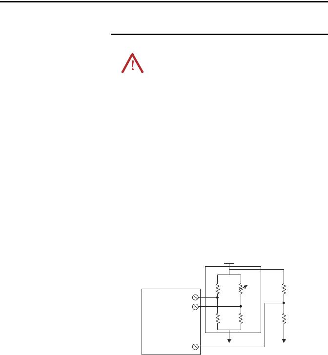
A large number of millivolt devices may be used with the 1746-NT4 module. For this reason we do not specify compatibility with any particular device.
However, millivolt applications often use bridges of strain gages. To allow the NT4 Series B (or higher) to operate correctly, the analog common (ANALOG COM) terminal of the module needs to be biased to a level within 2V of the signal of interest. A resistive voltage divider using 10k Ω resistors is recommended to accomplish this. The circuit diagram below shows how this connection is made.
|
Strain |
|
|
|
Gage |
Vcc + |
|
|
Bridge |
|
|
NT4 |
fixed |
variable |
10k Ω |
|
|||
INPUT |
+ |
|
|
(CHL0, CHL1, |
- |
|
|
CHL2, CHL3) |
|
|
10k Ω |
|
fixed |
fixed |
|
ANALOG COM |
|
|
|
Publication 1746-UM007C-EN-P - July 2004

1-8 Overview
Publication 1746-UM007C-EN-P - July 2004
Chapter 2
Required Tools and
Equipment
Quick Start for Experienced Users
This chapter can help you to get started using the NT4 4-channel thermocouple/mV module. The procedures are based on the assumption that you have an understanding of SLC 500 products. You should understand electronic process control and be able to interpret the ladder logic instructions required to generate the electronic signals that control your application.
Because it is a start-up guide for experienced users, this chapter does not contain detailed explanations about the procedures listed. It does, however, reference other chapters in this book where you can get more information about applying the procedures described in each step. It also references other documentation that may be helpful if you are unfamiliar with programming techniques or system installation requirements.
If you have any questions or are unfamiliar with the terms used or concepts presented in the procedural steps, always read the referenced chapters and other recommended documentation before trying to apply the information.
This chapter includes:
•Required Tools and Equipment
•Installation Procedures
Have the following tools and equipment ready:
•medium blade screwdriver
•medium cross-head screwdriver
•thermocouple or millivolt sensor
•appropriate thermocouple extension wire (if needed)
•4-channel thermocouple/mV input module (1746-NT4)
•programming equipment
Publication 1746-UM007C-EN-P - July 2004

2-2 Quick Start for Experienced Users
Installation Procedures
1. |
Check the contents of shipping box. |
Reference |
|
|
|
Unpack the shipping box making sure that the contents include:
• thermocouple input module (Catalog Number 1746-NT4)
• removeable terminal block (factory installed on module) with CJC sensors attached.
• installation instructions (publication 1746-IN010)
If the contents are incomplete, call your local Allen-Bradley representative for assistance.
|
|
2. |
Ensure your chassis supports placement of the 1746-NT4 module |
Reference |
|
|
|
|
|
|
|
|
Review the power requirements of your system to see that your chassis supports placement of the |
Chapter 3 |
|
|
|
thermocouple input module. |
(Installion and |
|
|
|
• For modular style systems, calculate the total load on the system power supply using the |
Wiring |
|
|
|
Appendix A |
|
|
|
|
procedure described in the SLC 500 Modular Hardware Style User Manual (Publication |
|
|
|
|
Number 1747-UM011) or the SLC 500 Modular Chassis and Power Supplies Technical Data |
(Specifications) |
|
|
|
||
|
|
|
(Publication Number 1746-TD003). |
|
•The fixed, 2-slot chassis supports 2 thermocouple input modules. If combining a thermocouple module with a different module, refer to the module compatibility table found in chapter 3.
Publication 1746-UM007C-EN-P - July 2004
Quick Start for Experienced Users |
2-3 |
|
|
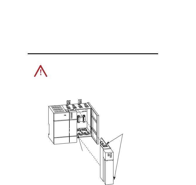
3. |
Insert the 1746-NT4 module into the chassis |
Reference |
|
|
|
|
Make sure system power is off; then insert the thermocouple input module into your 1746 |
Chapter 3 |
|
chassis. In this example procedure, local slot 1 is selected. |
(Installation and |
|
|
Wiring) |
ATTENTION |
Never install, remove, or wire modules with power |
|||
applied to the chassis or devices wired to the |
||||
|
|
|
||
|
|
|
||
|
|
|
module. |
|
|
|
|
|
|
|
|
|
|
|
|
|
|
|
|
Top and Bottom
Module Release(s)
Card
Guide
Publication 1746-UM007C-EN-P - July 2004

2-4 Quick Start for Experienced Users
4. |
Connect the thermocouple wires |
|
|
|
|
|
|
|
Reference |
|||
|
|
|
|
|
|
|
|
|
|
|
|
|
|
Connect thermocouple wires to channel 0 on the module’s terminal block. Make sure both cold |
Chapter 3 |
||||||||||
|
junction compensation (CJC) assemblies are securely attached. |
|
|
|
|
|
|
|
(Installion and |
|||
|
|
|
|
|
|
|
|
|
|
|
|
Wiring |
|
Ground the shield drain wire at one end only. The preferred location is to the same point as the |
Appendix D |
||||||||||
|
sensor ground reference. For grounded thermocouples or mV sensors, this is at the sensor. For |
|||||||||||
|
(Thermocouple |
|||||||||||
|
insulated/ungrounded thermocouples, this is at the NT4 module. |
|
|
|
|
|
|
|
||||
|
|
|
|
|
|
|
|
Types |
||||
|
|
|
|
|
|
|
|
|
|
|
|
|
|
|
Terminal Block |
|
|
|
|
||||||
|
CJC A |
|
|
|
|
|
CHL 0+ |
|
|
|||
|
|
|
|
|
|
|
|
|
||||
|
|
|
|
|
|
|
|
|||||
|
|
|
|
|
|
|
||||||
|
Assembly |
|
|
|
|
|
|
|
|
|
|
|
|
|
|
|
|
|
CHL 0 |
_ |
|
|
|
||
|
SHIELD |
|
|
|
|
|
|
|
|
|||
|
|
|
|
|
|
|
|
|||||
|
|
|
|
|
|
|
|
|||||
|
|
|
|
|
|
|
|
|||||
|
|
|
|
|
|
CHL 1+ |
|
|||||
|
SHIELD |
|
|
|
|
|
|
|||||
|
|
|
|
|
|
|
||||||
|
|
|
|
|
|
|
|
CHL 1 |
_ |
Thermocouple |
|
|
|
|
|
|
|
|
|
|
|
||||
|
|
|
|
|
|
|
|
|
||||
|
|
|
|
|
|
|
|
|
|
|
||
|
|
|
|
|
|
|
|
|
|
Wire |
|
|
|
|
|
|
|
|
Refer to the paragraph above |
|
|||||
|
|
|
|
|
|
|
||||||
|
|
|
|
|
|
|
||||||
5. |
Configure the system. |
Reference |
|
|
|
|
Configure your system I/O configuration for the particular slot the NT4 is in (slot 1 in this |
Chapter 4 |
|
example). Select the module from the drop-down list or enter the thermocouple input module ID |
(Preliminary |
|
code (3510). |
Operating |
|
|
Considerations) |
When using RSLogix 500 version 6.10 or higher, you may select Advanced Configuration, then Configure, to use the software’s I/O wizard to configure the NT4 (see appendix E for details). If you use this option, proceed to step 8.
Your programming software online help screens
Publication 1746-UM007C-EN-P - July 2004

Quick Start for Experienced Users |
2-5 |
|
|
6. |
Determine the operating parameters. |
Reference |
|
|
|
|
Determine the operating parameters for channel 0. This example shows the channel 0 |
Chapter 4 |
|
configuration word defined with all defaults (0) except for channel enable (bit 11). The |
(Preliminary |
|
addressing reflects the location of the module as slot 1. |
Operating |
|
|
Considerations) |
Chapter 5
(Channel
Configuration, Data, and Status)
Appendix B
(NT4 Configuration Worksheet)
SLC 500 Controller
Data Files
Input Image |
|
Output Image |
|
(8 words) |
|
|
|
|
|
|
|
Address
O:1.0 Word 0 Channel 0 Configuration Word 
 0
0
O:1.1 |
Word 1 |
Channel 1 Configuration Word |
O:1.2 |
Word 2 |
Channel 2 Configuration Word |
O:1.3 |
Word 3 |
Channel 3 Configuration Word |
• |
• |
Words 4 _7 |
• |
• |
|
• |
• |
(not defined) |
|
||
O:1.7 |
Word 7 |
|
Bit 15
Unused |
|
|
|
Channel Enable |
Filter Frequency |
|
Temperature Units |
Open Circuit |
|
Data Format |
|
|
|
InputType |
|
|
|
|||||
0 |
|
0 |
|
0 |
0 |
0 |
|
0 |
0 |
0 |
|
0 |
0 |
|
0 |
0 |
|
0 |
|
0 |
|
0 |
|
|
|
|
|
|
|
|
|||||||||||||||
Default Setting
•Type J Thermocouple
•Engineering Units x 1
•Data Word = 0 If Open Circuit
•Degrees Celsius
•10 Hz. Filter Frequency
•Channel Disabled
Bit 0
0 0 0 0 1 0 0 0 0 0 0 0 0 0 0 0
New Setting
Set this bit (11) to enable channel. Address = O:1.0/11.
Publication 1746-UM007C-EN-P - July 2004

2-6 Quick Start for Experienced Users
7. |
Program the configuration. |
Reference |
|
|
|
|
Do the programming necessary to establish the new configuration word setting in the previous |
Chapter 6 |
|
step. |
(Ladder |
|
Programming |
|
|
1. Create integer file N10. Integer file N10 should contain one element for each channel used. |
|
|
Examples) |
(For this example we only need one, N10:0.) |
Chapter 8 |
|
2. Enter the configuration parameters from step 6 for channel 0 into integer N10:0. |
||
(Application |
||
In this example all the bits of N10:0 will be zero except for the channel enable (N10:0/11). |
||
Examples) |
||
3. Program an instruction in your ladder logic to copy the contents of N10:0 to output word O:1.0. |
||
|
Example of Data Table for Integer File N10:
|
address |
15 |
|
|
data |
0 |
|
|
N10:0 |
0000 1000 0000 |
0000 |
||||
|
First Pass Bit |
|
|
|
|
||
|
|
|
|
|
|||
|
S:1 |
|
|
|
COP |
|
|
|
|
|
|
|
|||
|
|
|
|
|
|
||
|
] [ |
|
|
|
COPY FILE |
||
|
15 |
|
|
|
Source # N10:0 |
||
|
|
|
|
|
|
|
|
|
|
|
|
Dest # O:1.0 |
|||
|
|
|
|
Length 1 |
|
||
address |
15 |
data |
0 |
On power up, the first pass bit (S:1/15) is set for one scan, enabling the COPY instruction that transfers a one to bit 11 of channel configuration word 0. This enables the channel. .
8. |
Write the ladder program. |
|
|
|
|
|
|
|
|
|
|
|
|
|
|
|
|
|
|
|
|
Reference |
|||||||
|
|
|
|
|
|
|
|
|
|
|
|
|
|
|
|
|
|
|
|
|
|
|
|
|
|
|
|
|
|
|
Write the remainder of the ladder logic program that specifies how your thermocouple input data |
Chapter 5 |
|||||||||||||||||||||||||||
|
will be processed for your application. In this procedure the addressing reflects the location of |
(Channel |
|||||||||||||||||||||||||||
|
the module as slot 1. |
|
|
|
|
|
|
|
|
|
|
|
|
|
|
|
|
|
|
|
|
|
|
|
|
|
|
Configuration, |
|
|
|
|
|
|
|
|
|
|
|
|
|
|
|
|
|
|
|
|
|
|
|
|
|
|
|
|
|
|
Data, and |
|
|
|
|
|
|
|
|
|
|
|
|
|
|
|
|
|
|
|
|
|
|
|
|
|
|
|
|
|
Status) |
|
|
|
|
|
SLC 500 Controller |
|
|
|
|
|
|
|
|
|
|
|
|
|
|
Chapter 6 |
|||||||||
|
|
|
|
|
Data Files |
|
|
|
|
|
|
|
|
|
|
|
|
|
|
|
|
|
|
|
|
(Ladder |
|||
|
|
|
|
Input Image |
|
|
Output Image |
|
|
|
|
|
|
|
|
|
|
|
|
|
|
|
Programming |
||||||
|
|
|
|
|
|
|
|
|
|
|
|
|
|
|
|
|
|
|
|
|
Examples) |
||||||||
|
|
|
|
(8 words) |
|
|
|
|
|
|
|
|
|
|
|
|
|
|
|
|
|
||||||||
|
|
|
|
|
|
|
|
|
|
|
|
|
|
|
|
|
|
Address |
Chapter 8 |
||||||||||
|
|
|
|
|
|
|
|
|
|
|
|
|
|
|
|
|
|
||||||||||||
|
|
|
|
|
|
|
|
|
|
|
|
|
|
|
|
|
|
||||||||||||
|
Address |
|
|
|
|
|
|
|
|
|
|
|
|
|
|
|
|
|
I:1.0 |
(Application |
|||||||||
|
I:1.0 |
Word 0 |
Channel 0 DataWord |
|
|
0 |
0 |
0 |
0 |
0 |
0 |
0 |
0 |
0 |
0 |
0 |
0 |
0 |
0 |
0 |
0 |
|
Examples) |
||||||
|
|
||||||||||||||||||||||||||||
|
I:1.1 |
Word 1 |
Channel 1 Data Word |
|
Bit 15 |
(Variable Thermocouple Input Data) Bit 0 |
Your |
||||||||||||||||||||||
|
I:1.2 |
Word 2 |
Channel 2 Data Word |
|
|
|
|
|
|
|
|
|
|
|
|
|
|
|
|
|
|
|
|
||||||
|
I:1.3 |
Word 3 |
Channel 3 Data Word |
|
|
|
|
|
|
|
|
|
|
|
|
|
|
|
|
|
|
|
|
programming |
|||||
|
|
|
|
|
|
|
|
|
|
|
|
|
|
|
|
|
|
|
|
|
|
|
|
|
|
|
device user |
||
|
• |
• |
Channel 0 Status Word |
|
|
|
|
|
|
|
|
|
|
|
|
|
|
|
|
|
|
|
|
||||||
|
|
|
|
|
|
|
|
|
|
|
|
|
|
|
|
|
|
|
|
|
|
|
|
manual. |
|||||
|
• |
• |
Channel 1 Status Word |
|
|
|
|
|
|
|
|
|
|
|
|
|
|
|
|
|
|
|
|
||||||
|
• |
• |
|
|
|
|
|
|
|
|
|
|
|
|
|
|
|
|
|
|
|
|
|
|
|
|
|
|
|
|
Channel 2 Status Word |
|
|
|
|
|
|
|
|
|
|
|
|
|
|
|
|
|
|
|
|
|
|||||||
|
|
|
|
|
|
|
|
|
|
|
|
|
|
|
|
|
|
|
|
|
|
|
|
||||||
|
I:1.7 |
Word 7 |
|
|
|
|
|
|
|
|
|
|
|
|
|
|
|
|
|
|
|
|
|
|
|||||
|
Channel 3 Status Word |
|
|
|
|
|
|
|
|
|
|
|
|
|
|
|
|
|
|
|
|
|
|||||||
|
|
|
|
|
|
|
|
|
|
|
|
|
|
|
|
|
|
|
|
|
|
|
|
|
|
|
|
|
|
Publication 1746-UM007C-EN-P - July 2004
Quick Start for Experienced Users |
2-7 |
|
|
9. |
Go through the system start-up proceedure. |
Reference |
|
|
|
|
Apply power. Download your program to the SLC and put the controller into Run mode. In this |
Chapter 7 |
|
example during a normal start up, the module status LED and channel status 0 LED turn on. |
(Module |
|
|
Diagnostics and |
|
|
Troubleshooting) |
|
|
|
|
|
|
|
|
|
|
|
|
|
|
|
INPUT |
|
|
|
|
|
|
|
|||
|
|
|
|
|
|
|
|
|
|
|
|
|
|
|
CHANNEL |
|
|
0 |
|
2 |
|
|
Channel LEDs |
|
|
|
|
STATUS |
|
|
|
|
|
|
|
|
|
|
|
|
|
|
1 |
|
3 |
|
|
|
|
||
|
|
|
|
|
|
|
|
|
|
|
||
|
|
|
|
|
|
|
|
|
|
|
Module Status LED |
|
|
|
MODULE STATUS |
|
|
|
|
||||||
|
|
|
|
|
|
|||||||
|
|
|
|
|
|
|||||||
|
|
THERMOCOUPLE/mV |
|
|
|
|
|
|||||
|
|
|
|
|
|
|
|
|
|
|
|
|
|
|
|
|
|
|
|
|
|
||||
10. |
Check module operation. |
|
|
|
|
|
|
Reference |
||||
|
|
|
||||||||||
|
(Optional) Monitor the status of input channel 0 to determine its configuration setting and |
Chapter 5 |
||||||||||
|
operational status. This is useful for troubleshooting when the blinking channel LED indicates |
(Channel |
||||||||||
|
that an error has occurred. If the Module Status LED is off, or if the Channel 0 LED is off or |
Configuration, |
||||||||||
blinking, refer to chapter 7. |
Data, and |
|
Status) |
||
|
||
|
Chapter 6 |
|
|
(Ladder |
|
|
Programming |
|
|
Examples) |
|
|
Chapter 8 |
|
|
(Application |
|
|
Examples) |
SLC 500 Controller
Data Files
|
Input Image |
|
Output Image |
|
|
||
|
(8 words) |
|
|
|
|
|
|
|
|
|
|
Word 0 |
Channel 0 Data Word |
Word 1 |
Channel 1 Data Word |
Word 2 |
Channel 2 Data Word |
Word 3 |
Channel 3 Data Word |
Channel 0 Status Word
•Channel 1 Status Word
•Channel 2 Status Word Word 7 Channel 3 Status Word
|
|
Configuration Error |
Over Range Error |
Under Range Error |
Open Circuit Error |
Channel Status |
Filter Frequency |
|
Temperature Units |
Open CircuitType |
|
Data Format |
|
|
Input Type |
|
|
|
||||
|
|
|
|
|
|
|
|
|
|
|
|
|
|
|
|
|
|
|
|
|
|
|
|
|
0 |
0 |
0 |
0 |
1 |
0 |
|
0 |
0 |
0 |
|
0 |
0 |
|
0 |
0 |
0 |
|
0 |
0 |
|
|
||||||||||||||||||||||
|
||||||||||||||||||||||
Bit 15 |
|
|
|
|
|
|
Address |
|
|
|
|
|
|
|
|
Bit 0 |
||||||
|
|
|
|
|
|
|
|
|
|
|
|
|
|
|
|
|
|
|
||||
I:1.4
For this example, during normal operation only bit 11 is set.
Publication 1746-UM007C-EN-P - July 2004

2-8 Quick Start for Experienced Users
Publication 1746-UM007C-EN-P - July 2004

Chapter 3
Installation and Wiring
Compliance to European Union Directives
This chapter provides:
•Compliance to European Union Directives
•Electrostatic Discharge
•NT4 Power Requirements
•Module Location in Chassis
•Module Installation and Removal
•Terminal Wiring
•Thermocouple Calibration
If this product has the CE mark it is approved for installation within the European Union and EEA regions. It has been designed and tested to meet the following directives.
EMC Directive
The Series B (or higher) 1746-NT4 is tested to meet Council Directive 89/336/EEC Electromagnetic Compatibility (EMC) and the following standards, in whole or in part, documented in a technical construction file:
•EN 50081-2
EMC - Generic Emission Standard, Part 2 - Industrial Environment
•EN 50082-2
EMC - Generic Immunity Standard, Part 2 - Industrial Environment
This product is intended for use in an industrial environment.
Publication 1746-UM007C-EN-P - July 2004

3-2 Installation and Wiring
Electrostatic Discharge
Electrostatic discharge can damage semiconductor devices inside this module if you touch backplane connector pins. Guard against electrostatic damage by observing the precautions listed next.
ATTENTION |
Electrostatic discharge can degrade performance or |
|||
cause permanent damage. Handle the module as |
||||
|
|
|
||
|
|
|
||
|
|
|
stated below. |
|
|
|
|
|
|
|
|
|
|
|
|
|
|
|
|
•Wear an approved wrist strap grounding device when handling the module.
•Touch a grounded object to rid yourself of electrostatic charge before handling the module.
•Handle the module from the front, away from the backplane connector. Do not touch backplane connector pins.
•Keep the module in its static-shield bag when not in use, or during shipment.
NT4 Power Requirements |
The thermocouple module receives its power through the SLC500 |
|
chassis backplane from the fixed or modular +5 VDC/+24 VDC chassis |
|
power supply. The maximum current drawn by the module is shown |
|
in the table below. |
5V dc Amps |
24V dc Amps |
|
|
0.06 |
0.04 |
|
|
When you are using a modular system configuration, add the values shown in the table above to the requirements of all other modules in the SLC chassis to prevent overloading the chassis power supply.
When you are using a fixed system controller, refer to the important note about module compatibility in a 2-slot expansion chassis on page 3-3.
Publication 1746-UM007C-EN-P - July 2004
Loading...