


Reference Manual
Bulletin 1606 Switched Mode Power Supplies
Catalog Number: 1606-XLP15A
Index
|
|
Page |
|
|
|
Page |
1. |
Intended Use ....................................................... |
3 |
18. Certifications ................................................... |
15 |
||
2. |
Installation Requirements................................... |
3 |
19. |
Physical Dimensions and Weight ..................... |
16 |
|
3. |
AC-Input............................................................... |
4 |
20. |
Application Notes ............................................. |
17 |
|
4. |
DC-Input............................................................... |
5 |
20.1. |
Peak Current Capability ........................... |
17 |
|
5. |
Input Inrush Current ........................................... |
5 |
20.2. |
Back-feeding Loads .................................. |
17 |
|
6. |
Output ................................................................. |
6 |
20.3. |
External Input Protection ......................... |
18 |
|
7. |
Hold-up Time....................................................... |
7 |
20.4. |
Parallel Use to Increase Output Power .... |
18 |
|
8. |
Efficiency and Power Losses................................ |
8 |
20.5. |
Parallel Use for Redundancy .................... |
19 |
|
9. |
Functional Diagram............................................. |
9 |
20.6. |
Series Operation ....................................... |
19 |
|
10. |
Front Side and User Elements............................. |
9 |
20.7. |
Inductive and Capacitive Loads ................ |
19 |
|
11. |
Terminals and Wiring........................................ |
10 |
20.8. |
Operation on Two Phases ........................ |
20 |
|
12. |
Lifetime Expectancy and MTBF......................... |
10 |
20.9. |
Use Without PE on the Input ................... |
20 |
|
13. |
EMC .................................................................... |
11 |
20.10. Use in a Tightly Sealed Enclosure ............ |
21 |
||
14. |
Environment ...................................................... |
12 |
20.11. Mounting Orientations ............................ |
22 |
||
15. |
Protection Features ........................................... |
13 |
|
|
|
|
16. |
Safety Features .................................................. |
13 |
|
|
|
|
17. |
Dielectric Strength ............................................ |
14 |
|
|
|
|
Terminology and Abbreviations
•PE and  symbol—PE is the abbreviation for Protective Earth and has the same meaning as the symbol
  .
.
•Earth, Ground—This document uses the term “earth” which is the same as the U.S. term “ground”.
•T.b.d.—To be defined, value or description will follow later.
•AC 230V—A figure displayed with the AC or DC before the value represents a nominal voltage with standard tolerances (usually ±15%) included. E.g.: DC 12V describes a 12V battery disregarding whether it is full (13.7V) or flat (10V)
•230Vac—A figure with the unit (Vac) at the end is a momentary figure without any additional tolerances included.
•50Hz vs. 60Hz—As long as not otherwise stated, AC 230V parameters are valid at 50Hz mains frequency.
•may—A key word indicating flexibility of choice with no implied preference.
•shall—A key word indicating a mandatory requirement.
•should—A key word indicating flexibility of choice with a strongly preferred implementation.
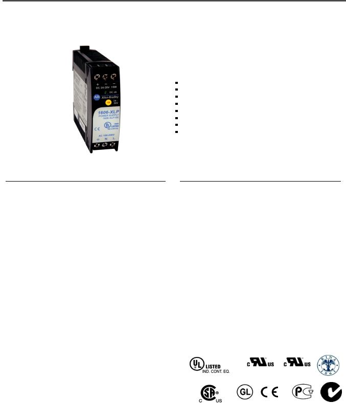
Bulletin 1606 Switched Mode Power Supplies
Power Supply
100-240V Wide Range Input NEC Class 2 Compliant Adjustable Output Voltage Efficiency up to 77.2%
Compact Design, Width only 22.5mm
Full Output Power Between -10°C and +60°C Large International Approval Package
3 Year Warranty
Description
Compact size, light weight, simple installation onto the DIN rail and the integration of only the highest quality components are the factors that make the XLP family of power supplies so easy to deploy and use within seconds.
A rugged electrical and mechanical design as well as high immunity against electrical disturbances on the mains provide reliable output power. This power supply offers superior protection for equipment connected to the public mains network or exposed to a critical industrial environment.
The XLP family of power supplies offers output voltages from 5 to 56Vdc and power ratings from 15W to 120W.
 Specification Quick Reference
Output voltage |
DC 5V |
|
Adjustment range |
5 – 5.5V |
|
Output current |
3A at 5V |
|
Output power |
15W |
|
Output ripple |
< 50mVpp |
20Hz to 20MHz |
Input voltage |
AC 100-240V |
-15% / +10% |
Mains frequency |
50-60Hz |
±6% |
AC Input current |
0.28 / 0.17A |
at 120 / 230Vac |
Power factor |
0.51 / 0.44 |
at 120 / 230Vac |
AC Inrush current |
typ. 16 /31A |
peak value at |
|
|
120/230Vac, 40°C |
|
|
and cold start |
DC Input |
88-375Vdc |
|
Efficiency |
76.8 / 77.2% |
at 120 / 230Vac |
Losses |
4.6 / 4.5W |
at 120 / 230Vac |
Temperature range |
-10°C to +70°C |
operational |
Derating |
0.4W/°C |
+60 to +70°C |
Hold-up time |
typ. 45 / 186ms |
at 120 / 230Vac |
Dimensions |
22.5x75x91mm |
WxHxD |
Weight |
130g / 0.29lb |
|
|
Catalog Numbers |
|
|
|
Certifications |
|
|
|
||
|
|
1606-XLP15A |
|
|
|
|
|
|
|
|
|
Power Supply |
5V Standard unit |
|
|
|
|
||||
|
|
|
|
|
|
|
UL 60950-1 |
Class I Div 2 |
|
|
|
|
|
|
|
|
UL 508 |
NEC Class 2 |
|
Marine RINA |
|
|
|
|
|
|
|
CSA 22.2 No107.1 |
Marine EMC, LVD |
GOST R |
C-Tick |
|
|
|
|
|
|
|
|
|
|||
|
All parameters are specified at 5V, 3A, 230Vac, 25°C ambient and after a 5 minutes run-in time unless noted otherwise. |
2 |
Rockwell Automation Publication 1606-RM019A-EN-P — March 2014 |
Bulletin 1606 Switched Mode Power Supplies
1. Intended Use
• This device is designed for installation in an enclosure and is intended for the general professional use such as in industrial control, office, communication, and instrumentation equipment.
• Do not use this power supply in equipment where malfunction may cause severe personal injury or threaten human life.
• This device is designed for use in non-hazardous, ordinary or unclassified locations.
2. Installation Requirements
•This device may only be installed and put into operation by qualified personnel.
•This device does not contain serviceable parts. The tripping of an internal fuse is caused by an internal defect.
•Should damage or malfunction occur during installation or operation, immediately turn power off and send unit to the factory for inspection.
•Mount the unit on a DIN rail so that the terminals are located on the bottom of the unit. For other mounting orientations, refer to Mounting.
•This device is designed for convection cooling and does not require an external fan. Do not obstruct airflow and do not cover ventilation grid (e.g. cable conduits) by more than 30%!
•Keep the following installation clearances: 40mm on top, 20mm on the bottom, 5mm on the left and right sides are recommended when the device is loaded permanently with more than 50% of the rated power. Increase this clearance to 15mm in case the adjacent device is a heat source (e.g. another power supply).
SHOCK HAZARD: Do not use the power supply without proper grounding (Protective Earth). Use the terminal on the input block for earth connection and not one of the screws on the housing.
-Turn power off before working on the device. Protect against inadvertent re-powering
-Make sure that the wiring is correct by following all local and national codes
-Do not modify or repair the unit
-Do not open the unit as high voltages are present inside
-Use caution to prevent any foreign objects from entering the housing
-Do not use in wet locations or in areas where moisture or condensation can be expected
-Do not touch during power-on, and immediately after power-off. Hot surfaces may cause burns.
WARNING: EXPLOSION HAZARDS!
Substitution of components may impair suitability for this environment. Do not disconnect the unit or operate the voltage adjustment or S/P jumper unless power has been switched off or the area is known to be non-hazardous.
All parameters are specified at 5V, 3A, 230Vac, 25°C ambient and after a 5 minutes run-in time unless noted otherwise. |
|
Rockwell Automation Publication 1606-RM019A-EN-P — March 2014 |
3 |

Bulletin 1606 Switched Mode Power Supplies
 3. AC Input
AC input |
nom. |
AC 100-240V |
-15% / +10%, TN/TT/IT-mains |
||
AC input range |
|
85-264Vac |
continuous operation |
|
|
|
|
264–300Vac |
< 0.5s |
|
|
Allowed voltage L or N to earth |
max. |
300Vac |
|
|
|
Input frequency |
nom. |
50–60Hz |
±6% |
|
|
Turn-on voltage |
typ. |
59Vac |
steady-state value, see Fig. 3-1 |
||
Shut-down voltage |
typ. |
54Vac |
steady-state value, see Fig. 3-1 |
||
|
|
AC 100V |
AC 120V |
AC 230V |
|
Input current (rms) |
typ. |
0.34A |
0.28A |
0.17A |
at 5V, 3A see Fig. 3-3 |
|
|
|
|
|
|
Power factor *) |
typ. |
0.52 |
0.51 |
0.44 |
at 5V, 3A see Fig. 3-4 |
Crest factor **) |
typ. |
3.45 |
3.53 |
3.94 |
at 5V, 3A |
Start-up delay |
typ. |
630ms |
630ms |
630ms |
see Fig. 5 2 |
Rise time |
typ. |
10ms |
10ms |
10ms |
at 5V, 3A, see Fig. 3-2 |
|
|
|
|
|
|
Turn-on overshoot |
max. |
100mV |
100mV |
100mV |
see Fig. 3-2 |
*) |
The power factor is the ratio of the true (or real) power to the apparent power in an AC circuit. |
|
**) |
The crest factor is the mathematical ratio of the peak value to RMS value of the input current waveform. |
|
|
Fig. 3-1 Input voltage range |
Fig. 3-2 Turn-on behavior, definitions |
POUT |
Rated |
max. |
input range |
||
|
|
500ms |
Shut-down |
Turn-on |
VIN |
|
|
|
54V 59V 85V |
264V 300Vac |
|
Intput |
|
|
|
Voltage |
|
|
|
Output |
- 5% |
|
Overshoot |
|
|
||
Voltage |
|
|
|
|
Start-up |
Rise |
|
|
delay |
Time |
Fig. 3-3 Input current vs. output load
Input Current, typ.
0.4A
0.35 |
|
a) 100Vac |
a |
|
|||
|
|
|
0.30b) 120Vac 


 b
b
0.25 |
|
c) 230Vac |
|
0.20 


0.15


 c
c
0.10


0.05


Output Current
0
0 0.5 1.0 1.5 2.0 2.5 3.0A
Fig. 3-4 Power factor vs. output load
Power Factor, typ. |
|
|
|
|
|
0.55 |
a) 100Vac |
|
|
|
a |
|
|
|
|
||
0.50 |
b) 120Vac |
|
|
|
|
|
|
|
b |
||
|
c) 230Vac |
|
|
|
|
0.45 |
|
|
|
|
c |
0.40 |
|
|
|
|
|
0.35 |
|
Output Current |
|
|
|
0.30 |
|
|
|
||
|
|
|
|
|
|
0.5 |
1.0 |
1.5 |
2.0 |
2.5 |
3.0A |
|
All parameters are specified at 5V, 3A, 230Vac, 25°C ambient and after a 5 minutes run-in time unless noted otherwise. |
4 |
Rockwell Automation Publication 1606-RM019A-EN-P — March 2014 |
Bulletin 1606 Switched Mode Power Supplies
 4. DC Input
DC input |
nom. |
DC 110-300V |
-20%/+25% |
DC input range |
min. |
88-375Vdc |
continuous operation |
DC input current |
typ. |
0.16A / 0.057A |
110Vdc / 300Vdc, at 5V, 3A |
|
|
|
|
Turn-on voltage |
typ. |
80Vdc |
steady state value |
Shut-down voltage |
typ. |
60Vdc |
steady state value |
|
|
|
|
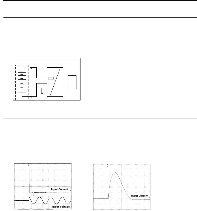
Fig. 4-1 |
Wiring for DC Input |
Instructions for DC use: |
|
Battery
Power Supply |
|
+ |
AC |
L |
internal |
fused |
|
|
+ |
N |
Load |
PE |
- |
|
|
- |
DC |
a)Use a battery or similar DC source.
For other sources, please contact Rockwell Automation.
b)Connect +pole to L and –pole to N.
c)Connect the PE terminal to an earth wire or to the machine ground.
 5. Input Inrush Current
A NTC limits the input inrush current after turn-on of the input voltage. The inrush current is input voltage and ambient temperature dependent.
The charging current into EMI suppression capacitors is disregarded in the first microseconds after switch-on.
|
|
AC 100V |
AC 120V |
AC 230V |
|
Inrush current |
max. |
13Apeak |
16Apeak |
31Apeak |
40°C ambient, cold start |
|
typ. |
11Apeak |
13Apeak |
26Apeak |
40°C ambient, cold start |
Inrush energy |
max. |
0.1A2s |
0.1A2s |
0.4A2s |
40°C ambient, cold start |
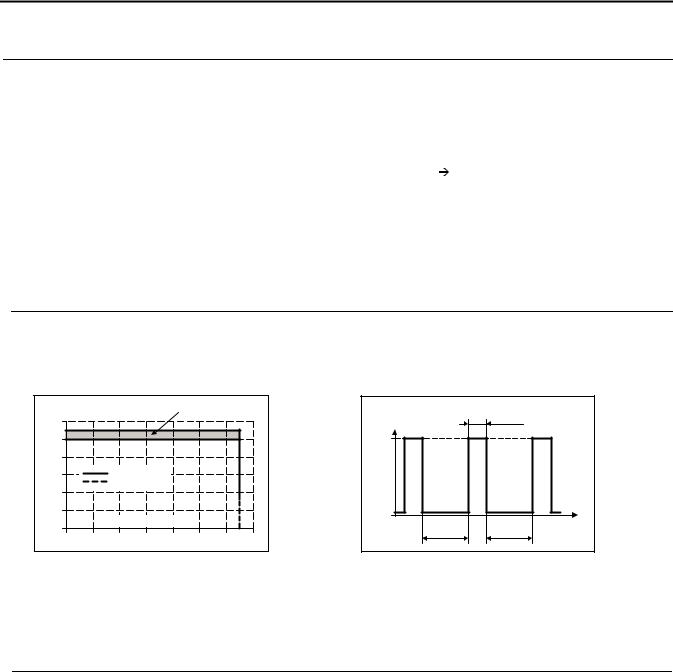
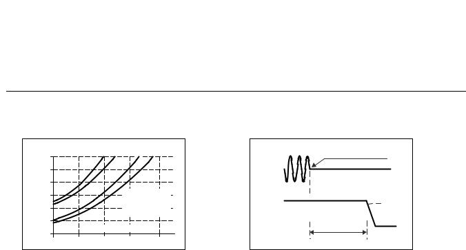
Fig. 5-1 Input inrush current, typical behavior |
Fig. 5-2 |
Input inrush current, zoom into first peak |
|||
Input: |
230Vac |
|
|
Output: |
5V, 3A |
Output: |
5V, 3A |
Ambient: |
25°C |
Ambient: |
25°C |
Upper curve: |
Input current 5A/DIV |
Input current curve: 5A/DIV, 500μs / DIV |
|
Lower curve: |
Input voltage 500V/DIV |
Ipeak |
23A |
Time basis: |
10ms / DIV |
|
|
All parameters are specified at 5V, 3A, 230Vac, 25°C ambient and after a 5 minutes run-in time unless noted otherwise. |
|
Rockwell Automation Publication 1606-RM019A-EN-P — March 2014 |
5 |
Bulletin 1606 Switched Mode Power Supplies
 6. Output
Output voltage |
nom. |
5V |
|
Adjustment range |
min. |
5-5.5V |
guaranteed |
|
max. |
6V *) |
at clockwise end position of potentiometer |
Factory setting |
|
5.1V |
±0.2%, at full load, cold unit |
Line regulation |
max. |
10mV |
85-264Vac |
Load regulation |
max. |
100mV |
static value, 0A 3A |
Ripple and noise voltage |
max. |
50mVpp |
20Hz to 20MHz, 50Ohm |
|
|
|
|
Output capacitance |
typ. |
4 800μF |
|
|
|
|
|
Output current |
nom. |
3A |
at 5V, see Fig. 6-1 |
|
nom. |
2.72A |
at 5.5V, see Fig. 6-1 |
|
|
|
|
Output power |
nom. |
15W |
|
Short-circuit current |
min. |
hiccup mode |
see Fig. 6-2 |
|
max. |
3A rms-current |
short circuit impedance <10mOhm, unit makes start-up |
|
|
|
attempts at short-circuit (hiccup mode) |
*) This is the maximum output voltage which can occur at the clockwise end position of the potentiometer due to tolerances. There is no guarantee this value can be achieved. The typical value achievable by turning the potentiometer to the clockwise end position
is 5.8V.
Fig. 6-1 Output voltage vs. output current, typ.
Fig. 6-2 Hiccup mode; output current at shorted output, 230Vac, typ.
Output Voltage |
|
Adjustment |
|
||||
6V |
|
|
|
|
Range |
|
|
|
|
|
|
|
|
|
|
5 |
|
|
|
|
|
|
|
4 |
|
|
|
|
|
|
|
3 |
|
Continuous |
|
|
|
|
|
2 |
|
Hiccup Mode |
|
|
|
|
|
|
|
|
|
|
|
|
|
1 |
|
Output Current |
|
|
|
||
0 |
|
|
|
|
|||
|
|
|
|
|
|
|
|
0 |
0.5 |
1.0 |
1.5 |
2.0 |
2.5 |
3.0 |
3.5A |
Output |
45ms |
Current |
|
3.3A |
|
0 |
t |
|
|
235ms |
235ms |
Peak current capability (up to several milliseconds)
The power supply can deliver a peak current which is higher than the specified short term current. This helps to start current demanding loads or to safely operate subsequent circuit breakers.
The extra current is supplied by the output capacitors inside the power supply. During this event, the capacitors will be discharged and causes a voltage dip on the output. Detailed curves can be found in section 20.1.
Peak current voltage dips |
typ. |
from 5V to 2.4V |
at 6A for 50ms, resistive load |
|
typ. |
from 5V to 1.0V |
at 15A for 2ms, resistive load |
|
typ. |
from 5V to 0.8V |
at 15A for 5ms, resistive load |
|
|
|
|
|
All parameters are specified at 5V, 3A, 230Vac, 25°C ambient and after a 5 minutes run-in time unless noted otherwise. |
6 |
Rockwell Automation Publication 1606-RM019A-EN-P — March 2014 |
|
|
|
|
|
|
|
Bulletin 1606 Switched Mode Power Supplies |
||
|
|
|
|
|
|
|
|
|
|
|
7. Hold-up Time |
|
|
|
|
|
|
|
|
|
|
|
|
|
|
|
|
||
|
|
|
|
AC 100V |
AC 120V |
AC 230V |
|
|
|
|
|
|
|
|
|
|
|||
|
Hold-up Time |
typ. |
61ms |
93ms |
340ms |
at 5V, 1.5A, see Fig. 7-1 |
|||
|
|
|
typ. |
29.5ms |
45ms |
186ms |
at 5V, 3A, see Fig. 7-1 |
||
Note: At no load, the hold-up time can be up to several seconds. The green DC-ok lamp is also on at this time.
Fig. 7-1 Hold-up time vs. input voltage
Hold-up Time
150ms |
|
a |
b |
c |
d |
|
|
|
|
|
|
125 |
|
|
|
|
|
100 |
|
|
|
|
|
75 |
|
|
|
a) 5V 1.5A typ. |
|
|
|
|
b) 5V 1.5Amin. |
||
|
|
|
|
||
50 |
|
|
|
c) 5V 3A typ. |
|
|
|
|
d) 5V 3A min. |
||
|
|
|
|
||
25 |
|
Input Voltage |
|
||
0 |
|
|
|||
|
|
|
|
|
|
85 |
120 |
155 |
|
190 |
230Vac |
Fig. 7-2 Shut-down behavior, definitions
Zero Transition
Input
Voltage
Output |
|
|
|
- 5% |
|
|
|
||
|
|
|
||
Voltage |
|
|
|
|
|
|
|
||
|
|
Hold-up Time
All parameters are specified at 5V, 3A, 230Vac, 25°C ambient and after a 5 minutes run-in time unless noted otherwise. |
|
Rockwell Automation Publication 1606-RM019A-EN-P — March 2014 |
7 |

Bulletin 1606 Switched Mode Power Supplies
 8. Efficiency and Power Losses
|
|
AC 100V |
AC 120V |
AC 230V |
|
Efficiency |
typ. |
75.8% |
76.8% |
77.2% |
at 5V, 3A (full load) |
Power losses |
typ. |
0.2W |
0.3W |
0.6W |
at 0A |
|
typ. |
2.3W |
2.3W |
2.4W |
at 5V, 1.5A (half load) |
|
typ. |
4.9W |
4.6W |
4.5W |
at 5V, 3A (full load) |
Fig. 8-1 Efficiency vs. output current at 5V, typ.
Fig. 8-2 Losses vs. output current at 5V, typ.
Efficiency |
|
|
|
|
|
|
Power Losses |
|
|
|
|
|
||
|
|
|
|
|
|
5W |
|
|
|
|
|
a |
||
78% |
|
|
|
|
|
|
|
|
|
|
|
|||
|
|
|
|
|
c |
|
a) 100Vac |
|
|
|
b |
|||
77 |
|
|
|
|
|
4 |
b) 120Vac |
|
|
|
c |
|||
76 |
|
|
|
|
|
b |
|
c) 230Vac |
|
|
|
|
||
|
|
|
|
|
a |
3 |
|
|
|
|
|
|
||
75 |
|
|
|
|
|
|
|
|
|
|
|
|
||
|
|
|
|
|
|
|
|
|
|
|
|
|
||
74 |
|
|
|
a) 100Vac |
2 |
|
|
|
|
|
|
|||
73 |
|
|
|
|
|
|
|
|
|
|||||
|
|
|
|
|
|
|
|
|
|
|||||
72 |
|
|
|
b) 120Vac |
1 c |
|
|
|
|
|
|
|||
|
|
|
c) 230Vac |
|
|
|
|
|
|
|||||
71 |
|
Output Current |
|
|
b |
|
Output Current |
|
||||||
70 |
|
|
|
0 a |
|
|
|
|
|
|
||||
|
|
|
|
|
|
0 |
0.5 |
1.0 |
1.5 |
2.0 |
2.5 |
3.0A |
||
0 |
0.5 |
1.0 |
1.5 |
2.0 |
2.5 |
3.0A |
||||||||
|
|
|
|
|
|
|
||||||||
Fig. 8-3 Efficiency vs. input voltage at 5V, 3A, typ.
Efficiency |
|
|
|
|
78% |
|
|
|
|
77 |
|
|
|
|
76 |
|
|
|
|
75 |
|
|
|
|
74 |
|
|
|
|
73 |
|
Input Voltage |
|
|
72 |
|
|
||
|
|
|
|
|
85 |
120 |
155 |
190 |
225 260Vac |
Fig. 8-4 Losses vs. input voltage at 5V, 3A, typ.
Power Losses |
|
|
|
|
5W |
|
|
|
|
4.75 |
|
|
|
|
4.50 |
|
|
|
|
4.25 |
|
|
|
|
4.00 |
|
|
|
|
3.75 |
|
Input Voltage |
|
|
|
|
|
|
|
85 |
120 |
155 |
190 |
225 260Vac |
|
All parameters are specified at 5V, 3A, 230Vac, 25°C ambient and after a 5 minutes run-in time unless noted otherwise. |
8 |
Rockwell Automation Publication 1606-RM019A-EN-P — March 2014 |
 Loading...