


 Loading...
User Manual
ControlLogix HART Analog I/O Modules
Catalog Numbers 1756-IF8H, 1756-IF16H, 1756-OF8H

Important User Information
Solid-state equipment has operational characteristics differing from those of electromechanical equipment. Safety Guidelines for the Application, Installation and Maintenance of Solid State Controls (publication SGI-1.1 available from your local Rockwell Automation sales office or online at http://www.rockwellautomation.com/literature/) describes some important differences between solid-state equipment and hard-wired electromechanical devices. Because of this difference, and also because of the wide variety of uses for solid-state equipment, all persons responsible for applying this equipment must satisfy themselves that each intended application of this equipment is acceptable.
In no event will Rockwell Automation, Inc. be responsible or liable for indirect or consequential damages resulting from the use or application of this equipment.
The examples and diagrams in this manual are included solely for illustrative purposes. Because of the many variables and requirements associated with any particular installation, Rockwell Automation, Inc. cannot assume responsibility or liability for actual use based on the examples and diagrams.
No patent liability is assumed by Rockwell Automation, Inc. with respect to use of information, circuits, equipment, or software described in this manual.
Reproduction of the contents of this manual, in whole or in part, without written permission of Rockwell Automation, Inc., is prohibited.
Throughout this manual, when necessary, we use notes to make you aware of safety considerations.
WARNING: Identifies information about practices or circumstances that can cause an explosion in a hazardous environment, which may lead to personal injury or death, property damage, or economic loss.
ATTENTION: Identifies information about practices or circumstances that can lead to personal injury or death, property damage, or economic loss. Attentions help you identify a hazard, avoid a hazard, and recognize the consequence
SHOCK HAZARD: Labels may be on or inside the equipment, for example, a drive or motor, to alert people that dangerous voltage may be present.
BURN HAZARD: Labels may be on or inside the equipment, for example, a drive or motor, to alert people that surfaces may reach dangerous temperatures.
IMPORTANT Identifies information that is critical for successful application and understanding of the product.
Allen-Bradley, Rockwell Software, Rockwell Automation, ControlLogix, RSLogix 5000, Logix5000, RSLinx, FactoryTalk AssetCentre, and TechConnect are trademarks of Rockwell Automation, Inc.
Trademarks not belonging to Rockwell Automation are property of their respective companies.

Summary of Changes
New and Updated
Information
This manual contains new and updated information. Changes throughout this revision are marked by changes bars, as shown to the right of this paragraph.
This table contains the changes made to this revision.
Topic |
Page |
|
|
|
|
|
|
Additional Input Data tag, Analog and HART by Channel, is available |
54, 80 |
|
|
|
|
||
for the 1756-IF8H and 1756-OF8H analog I/O modules. |
|
|
|
|
|
|
|
Power supply wiring diagrams are available for the |
61 |
|
|
|
|
||
1756-IF8H analog input module. |
|
|
|
|
|
|
|
Unicast connection to streamline EtherNet/IP network broadcast |
51, 93 |
|
|
|
|
||
traffic is available for the 1756-IF8H and 1756-OF8H analog |
|
|
|
I/O modules. |
|
|
|
|
|
|
|
Additional device diagnostics are available on the HART Device |
111 |
|
|
Info tab. |
|
|
|
|
|
|
|
Tag definitions are updated for the 1756-IF8H and 1756-OF8H analog |
163 |
|
|
|
|
||
I/O modules. |
|
|
|
|
|
|
|
Manufacturer identification codes are updated. |
205 |
|
|
|
|
||
|
|
|
|
Rockwell Automation Publication 1756-UM533C-EN-P - February 2011 |
3 |

Summary of Changes
4 |
Rockwell Automation Publication 1756-UM533C-EN-P - February 2011 |

|
Table of Contents |
|
Preface |
Audience . . . . . . . . . . . . . . . . . . . . . . . . . . . . . . . . . . . . . . . . . . . . . . . . . . . . . . . . |
11 |
|
Additional Resources . . . . . . . . . . . . . . . . . . . . . . . . . . . . . . . . . . . . . . . . . . . . . |
11 |
|
Chapter 1 |
|
ControlLogix HART |
Introduction. . . . . . . . . . . . . . . . . . . . . . . . . . . . . . . . . . . . . . . . . . . . . . . . . . . . . |
13 |
Analog I/O Modules |
Module Components. . . . . . . . . . . . . . . . . . . . . . . . . . . . . . . . . . . . . . . . . . . . . |
14 |
|
HART Communication . . . . . . . . . . . . . . . . . . . . . . . . . . . . . . . . . . . . . . . . . . |
14 |
|
Integrated HART Networks . . . . . . . . . . . . . . . . . . . . . . . . . . . . . . . . . . |
16 |
|
HART-enabled I/O Modules . . . . . . . . . . . . . . . . . . . . . . . . . . . . . . . . . |
16 |
|
Asset Management Software . . . . . . . . . . . . . . . . . . . . . . . . . . . . . . . . . . . . . . |
17 |
|
Electronic Keying . . . . . . . . . . . . . . . . . . . . . . . . . . . . . . . . . . . . . . . . . . . . . . . . |
17 |
|
Exact Match . . . . . . . . . . . . . . . . . . . . . . . . . . . . . . . . . . . . . . . . . . . . . . . . . |
18 |
|
Compatible Keying . . . . . . . . . . . . . . . . . . . . . . . . . . . . . . . . . . . . . . . . . . . |
19 |
|
Disabled Keying . . . . . . . . . . . . . . . . . . . . . . . . . . . . . . . . . . . . . . . . . . . . . . |
21 |
|
Timestamping . . . . . . . . . . . . . . . . . . . . . . . . . . . . . . . . . . . . . . . . . . . . . . . . . . . |
23 |
|
Module Scaling . . . . . . . . . . . . . . . . . . . . . . . . . . . . . . . . . . . . . . . . . . . . . . . . . . |
24 |
|
Chapter 2 |
|
Module Installation |
Introduction. . . . . . . . . . . . . . . . . . . . . . . . . . . . . . . . . . . . . . . . . . . . . . . . . . . . . |
25 |
|
Environment and Enclosure. . . . . . . . . . . . . . . . . . . . . . . . . . . . . . . . . . . . . . . |
26 |
|
Preventing Electrostatic Discharge. . . . . . . . . . . . . . . . . . . . . . . . . . . . . . . . . |
26 |
|
European Hazardous Location Approval . . . . . . . . . . . . . . . . . . . . . . . . . . . |
26 |
|
North American Hazardous Location Approval . . . . . . . . . . . . . . . . . . . . |
27 |
|
Removal and Insertion Under Power (RIUP). . . . . . . . . . . . . . . . . . . . . . . |
28 |
|
Before You Begin. . . . . . . . . . . . . . . . . . . . . . . . . . . . . . . . . . . . . . . . . . . . . . . . . |
28 |
|
Module Accessories . . . . . . . . . . . . . . . . . . . . . . . . . . . . . . . . . . . . . . . . . . . . . . |
28 |
|
Power Requirements . . . . . . . . . . . . . . . . . . . . . . . . . . . . . . . . . . . . . . . . . . . . . |
29 |
|
Install the Module. . . . . . . . . . . . . . . . . . . . . . . . . . . . . . . . . . . . . . . . . . . . . . . . |
30 |
|
Key the Removable Terminal Block/Interface Module . . . . . . . . . . . . . . |
31 |
|
Wire the Removable Terminal Block . . . . . . . . . . . . . . . . . . . . . . . . . . . . . . |
32 |
|
Ground the Module . . . . . . . . . . . . . . . . . . . . . . . . . . . . . . . . . . . . . . . . . . . . . . |
32 |
|
Connect the Grounded End of the Cable . . . . . . . . . . . . . . . . . . . . . . . |
32 |
|
Connect the Ungrounded End of the Cable . . . . . . . . . . . . . . . . . . . . |
33 |
|
Wire the Module. . . . . . . . . . . . . . . . . . . . . . . . . . . . . . . . . . . . . . . . . . . . . . . . . |
34 |
|
Removal Terminal Block Assembly and Installation. . . . . . . . . . . . . . . . . |
34 |
|
Assemble the Removable Terminal Block and the Housing . . . . . . |
34 |
|
Install the Removable Terminal Block. . . . . . . . . . . . . . . . . . . . . . . . . . |
35 |
|
Remove the Removable Terminal Block. . . . . . . . . . . . . . . . . . . . . . . . . . . . |
36 |
|
Remove the Module . . . . . . . . . . . . . . . . . . . . . . . . . . . . . . . . . . . . . . . . . . . . . . |
37 |
Rockwell Automation Publication 1756-UM533C-EN-P - February 2011 |
5 |

Table of Contents |
|
|
|
Chapter 3 |
|
ControlLogix Module Operation |
Introduction . . . . . . . . . . . . . . . . . . . . . . . . . . . . . . . . . . . . . . . . . . . . . . . . . . . . . |
39 |
|
Direct Connections. . . . . . . . . . . . . . . . . . . . . . . . . . . . . . . . . . . . . . . . . . . . . . . |
40 |
|
Input Module Operation. . . . . . . . . . . . . . . . . . . . . . . . . . . . . . . . . . . . . . . . . . |
40 |
|
Input Modules in a Local Chassis . . . . . . . . . . . . . . . . . . . . . . . . . . . . . . . . . . |
41 |
|
Real Time Sample (RTS) . . . . . . . . . . . . . . . . . . . . . . . . . . . . . . . . . . . . . . |
41 |
|
Requested Packet Interval (RPI) . . . . . . . . . . . . . . . . . . . . . . . . . . . . . . . |
42 |
|
Trigger Event Tasks. . . . . . . . . . . . . . . . . . . . . . . . . . . . . . . . . . . . . . . . . . . |
43 |
|
Input Modules in a Remote Chassis . . . . . . . . . . . . . . . . . . . . . . . . . . . . . . . . |
44 |
|
Remote Input Modules Connected Via ControlNet Network . . . . |
44 |
|
Remote Input Modules Connected Via EtherNet/IP Network . . . |
45 |
|
Output Module Operation . . . . . . . . . . . . . . . . . . . . . . . . . . . . . . . . . . . . . . . . |
46 |
|
Output Modules in a Local Chassis . . . . . . . . . . . . . . . . . . . . . . . . . . . . . . . . |
46 |
|
Output Modules in a Remote Chassis . . . . . . . . . . . . . . . . . . . . . . . . . . . . . . |
47 |
|
Remote Output Modules Connected Via ControlNet Network . . |
47 |
|
Remote Output Modules Connected Via EtherNet/IP Network . 48 |
|
|
Listen-only Mode. . . . . . . . . . . . . . . . . . . . . . . . . . . . . . . . . . . . . . . . . . . . . . . . . |
49 |
|
Multiple Owners of Input Modules . . . . . . . . . . . . . . . . . . . . . . . . . . . . . . . . |
49 |
|
Configuration Changes in an Input Module with Multiple Owners. . . |
51 |
|
Unicast Communication. . . . . . . . . . . . . . . . . . . . . . . . . . . . . . . . . . . . . . . . . . |
51 |
|
Chapter 4 |
|
1756-IF8H HART Analog |
Introduction . . . . . . . . . . . . . . . . . . . . . . . . . . . . . . . . . . . . . . . . . . . . . . . . . . . . . |
53 |
Input Module |
Module Features. . . . . . . . . . . . . . . . . . . . . . . . . . . . . . . . . . . . . . . . . . . . . . . . . . |
53 |
|
Data Formats. . . . . . . . . . . . . . . . . . . . . . . . . . . . . . . . . . . . . . . . . . . . . . . . . |
54 |
|
Input Ranges . . . . . . . . . . . . . . . . . . . . . . . . . . . . . . . . . . . . . . . . . . . . . . . . . |
54 |
|
Module Filter. . . . . . . . . . . . . . . . . . . . . . . . . . . . . . . . . . . . . . . . . . . . . . . . . |
55 |
|
Real Time Sampling. . . . . . . . . . . . . . . . . . . . . . . . . . . . . . . . . . . . . . . . . . . |
56 |
|
Underrange and Overrange Detection . . . . . . . . . . . . . . . . . . . . . . . . . . |
56 |
|
Digital Filter . . . . . . . . . . . . . . . . . . . . . . . . . . . . . . . . . . . . . . . . . . . . . . . . . |
57 |
|
Process Alarms . . . . . . . . . . . . . . . . . . . . . . . . . . . . . . . . . . . . . . . . . . . . . . . |
58 |
|
Rate Alarm . . . . . . . . . . . . . . . . . . . . . . . . . . . . . . . . . . . . . . . . . . . . . . . . . . . |
59 |
|
Wire-off Detection . . . . . . . . . . . . . . . . . . . . . . . . . . . . . . . . . . . . . . . . . . . |
59 |
|
Wiring Diagrams . . . . . . . . . . . . . . . . . . . . . . . . . . . . . . . . . . . . . . . . . . . . . . . . . |
60 |
|
Circuit Diagrams . . . . . . . . . . . . . . . . . . . . . . . . . . . . . . . . . . . . . . . . . . . . . . . . . |
62 |
|
1756-IF8H Module Fault and Status Reporting . . . . . . . . . . . . . . . . . . . . . |
63 |
|
1756-IF8H Fault Reporting . . . . . . . . . . . . . . . . . . . . . . . . . . . . . . . . . . . . . . . |
64 |
|
1756-IF8H Module Fault Word Bits . . . . . . . . . . . . . . . . . . . . . . . . . . . |
65 |
|
1756-IF8H Channel Fault Tags. . . . . . . . . . . . . . . . . . . . . . . . . . . . . . . . |
65 |
|
1756-IF8H Channel Status Tags . . . . . . . . . . . . . . . . . . . . . . . . . . . . . . . |
66 |
|
Specifications and Certifications . . . . . . . . . . . . . . . . . . . . . . . . . . . . . . . . . . . |
66 |
6 |
Rockwell Automation Publication 1756-UM533C-EN-P - February 2011 |

Table of Contents
1756-IF16H HART
Analog Input Module
1756-OF8H HART
Analog Output Module
Chapter 5
Introduction. . . . . . . . . . . . . . . . . . . . . . . . . . . . . . . . . . . . . . . . . . . . . . . . . . . . . 67
Module Features . . . . . . . . . . . . . . . . . . . . . . . . . . . . . . . . . . . . . . . . . . . . . . . . . 67
Data Formats . . . . . . . . . . . . . . . . . . . . . . . . . . . . . . . . . . . . . . . . . . . . . . . . 68
Input Ranges . . . . . . . . . . . . . . . . . . . . . . . . . . . . . . . . . . . . . . . . . . . . . . . . . 68
Module Filter . . . . . . . . . . . . . . . . . . . . . . . . . . . . . . . . . . . . . . . . . . . . . . . . 69
Real Time Sampling (RTS). . . . . . . . . . . . . . . . . . . . . . . . . . . . . . . . . . . . 70
Underrange and Overrange Detection. . . . . . . . . . . . . . . . . . . . . . . . . . 70
Digital Filter . . . . . . . . . . . . . . . . . . . . . . . . . . . . . . . . . . . . . . . . . . . . . . . . . 71
Wire-off Detection . . . . . . . . . . . . . . . . . . . . . . . . . . . . . . . . . . . . . . . . . . . 72
Wiring Diagram. . . . . . . . . . . . . . . . . . . . . . . . . . . . . . . . . . . . . . . . . . . . . . 72
Circuit Diagram . . . . . . . . . . . . . . . . . . . . . . . . . . . . . . . . . . . . . . . . . . . . . . . . . 74
1756-IF16H Module Fault and Status Reporting . . . . . . . . . . . . . . . . . . . 75
1756-IF16H Fault Reporting . . . . . . . . . . . . . . . . . . . . . . . . . . . . . . . . . . . . . 76
1756-IF16H Module Fault Word Bits . . . . . . . . . . . . . . . . . . . . . . . . . 77
1756-IF16H Channel Fault Tags . . . . . . . . . . . . . . . . . . . . . . . . . . . . . . 77
1756-IF16H Channel Status Tags . . . . . . . . . . . . . . . . . . . . . . . . . . . . . 77
Specifications and Certifications. . . . . . . . . . . . . . . . . . . . . . . . . . . . . . . . . . . 77
Chapter 6
Introduction. . . . . . . . . . . . . . . . . . . . . . . . . . . . . . . . . . . . . . . . . . . . . . . . . . . . . 79
Module Features . . . . . . . . . . . . . . . . . . . . . . . . . . . . . . . . . . . . . . . . . . . . . . . . . 79 Data Formats . . . . . . . . . . . . . . . . . . . . . . . . . . . . . . . . . . . . . . . . . . . . . . . . 80
Resolution . . . . . . . . . . . . . . . . . . . . . . . . . . . . . . . . . . . . . . . . . . . . . . . . . . . 80
Ramping/Rate Limiting. . . . . . . . . . . . . . . . . . . . . . . . . . . . . . . . . . . . . . . 81 Hold for Initialization . . . . . . . . . . . . . . . . . . . . . . . . . . . . . . . . . . . . . . . . 81
Open Wire Detection. . . . . . . . . . . . . . . . . . . . . . . . . . . . . . . . . . . . . . . . . 82
Clamping and Limiting . . . . . . . . . . . . . . . . . . . . . . . . . . . . . . . . . . . . . . . 82 Clamp and Limit Alarms. . . . . . . . . . . . . . . . . . . . . . . . . . . . . . . . . . . . . . 82
Data Echo . . . . . . . . . . . . . . . . . . . . . . . . . . . . . . . . . . . . . . . . . . . . . . . . . . . 83
Wire the Module. . . . . . . . . . . . . . . . . . . . . . . . . . . . . . . . . . . . . . . . . . . . . . . . . 83 Use Module Block and Output Circuit Diagrams . . . . . . . . . . . . . . . . . . . 84 1756-OF8H Module Fault and Status Reporting . . . . . . . . . . . . . . . . . . . 85
1756-OF8H Fault Reporting. . . . . . . . . . . . . . . . . . . . . . . . . . . . . . . . . . . . . . 86
Module Fault Word Bits . . . . . . . . . . . . . . . . . . . . . . . . . . . . . . . . . . . . . . 87 Channel Fault Word Bits . . . . . . . . . . . . . . . . . . . . . . . . . . . . . . . . . . . . . 87
Channel Status Tags . . . . . . . . . . . . . . . . . . . . . . . . . . . . . . . . . . . . . . . . . . 88
Specifications and Certifications. . . . . . . . . . . . . . . . . . . . . . . . . . . . . . . . . . . 88
Rockwell Automation Publication 1756-UM533C-EN-P - February 2011 |
7 |

Table of Contents
Configure the Modules with RSLogix 5000 Software
Getting HART Data
By Using CIP MSG
Chapter 7
Introduction . . . . . . . . . . . . . . . . . . . . . . . . . . . . . . . . . . . . . . . . . . . . . . . . . . . . . 89
Create a New Module. . . . . . . . . . . . . . . . . . . . . . . . . . . . . . . . . . . . . . . . . . . . . 89
General Tab. . . . . . . . . . . . . . . . . . . . . . . . . . . . . . . . . . . . . . . . . . . . . . . . . . . . . . 91 HART Configuration. . . . . . . . . . . . . . . . . . . . . . . . . . . . . . . . . . . . . . . . . 92
Connection Tab. . . . . . . . . . . . . . . . . . . . . . . . . . . . . . . . . . . . . . . . . . . . . . . . . . 93
Module Info Tab . . . . . . . . . . . . . . . . . . . . . . . . . . . . . . . . . . . . . . . . . . . . . . . . . 94 Status . . . . . . . . . . . . . . . . . . . . . . . . . . . . . . . . . . . . . . . . . . . . . . . . . . . . . . . . 94
Coordinated System Time (CST) . . . . . . . . . . . . . . . . . . . . . . . . . . . . . . 95
Refresh or Reset Module . . . . . . . . . . . . . . . . . . . . . . . . . . . . . . . . . . . . . . 95 Applying Changes . . . . . . . . . . . . . . . . . . . . . . . . . . . . . . . . . . . . . . . . . . . . 95
Configuration Tab - Input Modules. . . . . . . . . . . . . . . . . . . . . . . . . . . . . . . . 96
Configure the Individual Channels. . . . . . . . . . . . . . . . . . . . . . . . . . . . . 97 Scaling to Engineering Units. . . . . . . . . . . . . . . . . . . . . . . . . . . . . . . . . . . 98
Configure All Channels . . . . . . . . . . . . . . . . . . . . . . . . . . . . . . . . . . . . . . 101
Module Resolution . . . . . . . . . . . . . . . . . . . . . . . . . . . . . . . . . . . . . . . . . . 102
Alarm Tab - 1756-IF8H Module . . . . . . . . . . . . . . . . . . . . . . . . . . . . . . . . . 103 Configuration Tab - Output Module. . . . . . . . . . . . . . . . . . . . . . . . . . . . . . 105
Configure Individual Channels . . . . . . . . . . . . . . . . . . . . . . . . . . . . . . . 105
Configure All Channels . . . . . . . . . . . . . . . . . . . . . . . . . . . . . . . . . . . . . . 106 Output State Tab - Output Module. . . . . . . . . . . . . . . . . . . . . . . . . . . . . . . 107
Ramp Rate . . . . . . . . . . . . . . . . . . . . . . . . . . . . . . . . . . . . . . . . . . . . . . . . . . 107
Output State in Program Mode . . . . . . . . . . . . . . . . . . . . . . . . . . . . . . . 108 Output State in Fault Mode . . . . . . . . . . . . . . . . . . . . . . . . . . . . . . . . . . 108
Communication Failure . . . . . . . . . . . . . . . . . . . . . . . . . . . . . . . . . . . . . . 109
Limits Tab - Output Module . . . . . . . . . . . . . . . . . . . . . . . . . . . . . . . . . . . . . 109 HART Device Info Tab. . . . . . . . . . . . . . . . . . . . . . . . . . . . . . . . . . . . . . . . . . 111
Data in the Input Tags . . . . . . . . . . . . . . . . . . . . . . . . . . . . . . . . . . . . . . . . . . . 113
HART Dynamic Variables . . . . . . . . . . . . . . . . . . . . . . . . . . . . . . . . . . . 114 How the Module Automatically Collects Data . . . . . . . . . . . . . . . . . 117
Chapter 8
Introduction . . . . . . . . . . . . . . . . . . . . . . . . . . . . . . . . . . . . . . . . . . . . . . . . . . . . 121
Using MSG Instructions to Access the HART Object . . . . . . . . . . . . . . 122 CIP Services to Access Common HART Data . . . . . . . . . . . . . . . . . . . . . 123
Read Dynamic Variables (Service Code = 16#4B) . . . . . . . . . . . . . . 123
Read Additional Status (Service Code = 16#4C) . . . . . . . . . . . . . . . 125 Get Device Information (Service Code = 16#4D) . . . . . . . . . . . . . . 126
Getting HART Device Information By Using CIP Generic MSG . . . 128
CIP Services to Pass-through a HART Message to the
HART Field Device . . . . . . . . . . . . . . . . . . . . . . . . . . . . . . . . . . . . . . . . . . . . . 131
HART Module Scanning Diagram with Pass-through Messages . . . . . 133 HART Pass-through CIP Message Layout Details. . . . . . . . . . . . . . . . . . 134 Pass-through Init (Service Code= 16#4E). . . . . . . . . . . . . . . . . . . . . . 134 Pass-through Query (Service Code= 16#4F) . . . . . . . . . . . . . . . . . . . 134
8 |
Rockwell Automation Publication 1756-UM533C-EN-P - February 2011 |

Table of Contents
Flush Queue (Service Code= 16#50). . . . . . . . . . . . . . . . . . . . . . . . . . 136
HART Pass-through Message Ladder Logic Example. . . . . . . . . . . . . . . 136
HART Modules Used with Asset Management Software
Unlatch Alarms and
Reconfigure Modules
By Using Ladder Logic
Chapter 9
Introduction. . . . . . . . . . . . . . . . . . . . . . . . . . . . . . . . . . . . . . . . . . . . . . . . . . . . 141
Considerations for Asset Management Systems . . . . . . . . . . . . . . . . . . . . 141
Frequently Asked Questions . . . . . . . . . . . . . . . . . . . . . . . . . . . . . . . . . . . . . 142
Chapter 10
Introduction. . . . . . . . . . . . . . . . . . . . . . . . . . . . . . . . . . . . . . . . . . . . . . . . . . . . 145
Using Message Instructions . . . . . . . . . . . . . . . . . . . . . . . . . . . . . . . . . . . . . . 145
Processing Real-time Control and Module Services . . . . . . . . . . . . . 146
One Service Performed Per Instruction. . . . . . . . . . . . . . . . . . . . . . . . 146
Creating a New Tag . . . . . . . . . . . . . . . . . . . . . . . . . . . . . . . . . . . . . . . . . 146
Enter Message Configuration. . . . . . . . . . . . . . . . . . . . . . . . . . . . . . . . . 148
Unlatch Alarms in the 1756-IF8H Module. . . . . . . . . . . . . . . . . . . . . . . . 150
Unlatch Alarms in the 1756-OF8H Module. . . . . . . . . . . . . . . . . . . . . . . 152
Reconfigure a Module . . . . . . . . . . . . . . . . . . . . . . . . . . . . . . . . . . . . . . . . . . . 154
|
Chapter 11 |
|
Module Troubleshooting |
Introduction. . . . . . . . . . . . . . . . . . . . . . . . . . . . . . . . . . . . . . . . . . . . . . . . . . . . |
155 |
|
Use Module Indicators . . . . . . . . . . . . . . . . . . . . . . . . . . . . . . . . . . . . . . . . . . |
155 |
|
General Troubleshooting Tips . . . . . . . . . . . . . . . . . . . . . . . . . . . . . . . . . . . |
156 |
|
Use RSLogix 5000 Software to Troubleshoot a Module . . . . . . . . . . . . |
159 |
|
Module Configuration Errors . . . . . . . . . . . . . . . . . . . . . . . . . . . . . . . . . . . . |
160 |
|
Additional Fault Codes - Module Level. . . . . . . . . . . . . . . . . . . . . . . . |
160 |
|
Additional Fault Codes - Channel Level . . . . . . . . . . . . . . . . . . . . . . . |
161 |
|
Appendix A |
|
Tag Definitions |
Communication Mode Member Names and Definitions . . . . . . . . . . . |
163 |
|
Module-defined Data Types, 1756-IF8H Module. . . . . . . . . . . . . . . . . . |
164 |
|
Configuration. . . . . . . . . . . . . . . . . . . . . . . . . . . . . . . . . . . . . . . . . . . . . . . |
164 |
|
Analog Only . . . . . . . . . . . . . . . . . . . . . . . . . . . . . . . . . . . . . . . . . . . . . . . . |
165 |
|
Analog and HART PV. . . . . . . . . . . . . . . . . . . . . . . . . . . . . . . . . . . . . . . |
167 |
|
Analog and HART by Channel. . . . . . . . . . . . . . . . . . . . . . . . . . . . . . . |
170 |
|
Module-defined Data Types, 1756-IF16H Module . . . . . . . . . . . . . . . . |
173 |
|
Configuration. . . . . . . . . . . . . . . . . . . . . . . . . . . . . . . . . . . . . . . . . . . . . . . |
173 |
|
Analog Only . . . . . . . . . . . . . . . . . . . . . . . . . . . . . . . . . . . . . . . . . . . . . . . . |
174 |
|
Analog and HART PV. . . . . . . . . . . . . . . . . . . . . . . . . . . . . . . . . . . . . . . |
175 |
|
Analog and HART by Channel. . . . . . . . . . . . . . . . . . . . . . . . . . . . . . . |
178 |
|
Module-defined Data Types, 1756-OF8H Module. . . . . . . . . . . . . . . . . |
181 |
|
Configuration. . . . . . . . . . . . . . . . . . . . . . . . . . . . . . . . . . . . . . . . . . . . . . . |
181 |
|
Analog Only . . . . . . . . . . . . . . . . . . . . . . . . . . . . . . . . . . . . . . . . . . . . . . . . |
182 |
|
Analog and HART PV. . . . . . . . . . . . . . . . . . . . . . . . . . . . . . . . . . . . . . . |
184 |
Rockwell Automation Publication 1756-UM533C-EN-P - February 2011 |
9 |

Table of Contents |
|
|
|
Analog and HART by Channel . . . . . . . . . . . . . . . . . . . . . . . . . . . . . . . |
186 |
|
Output . . . . . . . . . . . . . . . . . . . . . . . . . . . . . . . . . . . . . . . . . . . . . . . . . . . . . |
189 |
|
Appendix B |
|
Use 1492 Wiring Systems |
Wiring System Uses . . . . . . . . . . . . . . . . . . . . . . . . . . . . . . . . . . . . . . . . . . . . . |
191 |
with Your Analog I/O Module |
|
|
|
Appendix C |
|
Additional HART |
Introduction . . . . . . . . . . . . . . . . . . . . . . . . . . . . . . . . . . . . . . . . . . . . . . . . . . . . |
193 |
Protocol Information |
Message Structure . . . . . . . . . . . . . . . . . . . . . . . . . . . . . . . . . . . . . . . . . . . . . . . |
194 |
|
Master-slave Operation. . . . . . . . . . . . . . . . . . . . . . . . . . . . . . . . . . . . . . . |
194 |
|
Multiple Master Operation . . . . . . . . . . . . . . . . . . . . . . . . . . . . . . . . . . . |
194 |
|
Transaction Procedure . . . . . . . . . . . . . . . . . . . . . . . . . . . . . . . . . . . . . . . |
194 |
|
Burst Mode . . . . . . . . . . . . . . . . . . . . . . . . . . . . . . . . . . . . . . . . . . . . . . . . . |
194 |
|
Response Code and Field Device Status . . . . . . . . . . . . . . . . . . . . . . . . . . . |
195 |
|
HART PV, SV, TV, and FV Status. . . . . . . . . . . . . . . . . . . . . . . . . . . . . . . . |
202 |
|
Appendix D |
|
Manufacturer ID Codes |
Introduction . . . . . . . . . . . . . . . . . . . . . . . . . . . . . . . . . . . . . . . . . . . . . . . . . . . . |
205 |
|
Appendix E |
|
Engineering Unit Code Numbers |
Code Number Details . . . . . . . . . . . . . . . . . . . . . . . . . . . . . . . . . . . . . . . . . . . |
213 |
Glossary |
. . . . . . . . . . . . . . . . . . . . . . . . . . . . . . . . . . . . . . . . . . . . . . . . . . . . . . . . . . . . . . . . |
219 |
Index |
. . . . . . . . . . . . . . . . . . . . . . . . . . . . . . . . . . . . . . . . . . . . . . . . . . . . . . . . . . . . . . . . |
223 |
10 |
Rockwell Automation Publication 1756-UM533C-EN-P - February 2011 |
Preface
Audience
Additional Resources
This manual describes how to install, configure, and troubleshoot ControlLogix highway addressable remote transducer (HART) analog I/O modules.
You must be able to program and operate a Rockwell Automation ControlLogix controller to efficiently use your analog I/O modules. In this manual, we assume that you know how to do this. If you do not, before attempting to use this module, refer to the Logix5000 controller documentation, as listed in the related table.
These documents contain additional information concerning related Rockwell Automation products.
Resource |
Description |
|
|
ControlLogix HART Analog I/O Modules Release |
Contains release information about the |
Notes, publication 1756-RN636 |
ControlLogix analog modules with |
|
HART protocol. |
|
|
Logix5000 Controllers Common Procedures |
Provides access to a collection of programming |
Programming Manual, publication 1756-PM001 |
manuals that describe procedures that are |
|
common to all Logix5000 controller projects. |
|
|
ControlLogix System User Manual, |
Provides configuration and operational |
publication 1756-UM001 |
procedures for ControlLogix controllers. |
|
|
1756 ControlLogix I/O Modules Specifications |
Publication provides specifications for the |
Technical Data, publication 1756-TD002 |
1756-IF8H and 1756-OF8H analog I/O modules. |
|
|
Industrial Automation Wiring and Grounding |
Provides general guidelines for installing a |
Guidelines, publication1770-4.1 |
Rockwell Automation industrial system. |
|
|
Product Certifications website, |
Provides declarations of conformity, certificates, |
http://www.ab.com |
and other certification details. |
|
|
You can view or download publications at http://www.rockwellautomation.com/ literature/. To order paper copies of technical documentation, contact your local Rockwell Automation distributor or sales representative.
Rockwell Automation Publication 1756-UM533C-EN-P - February 2011 |
11 |

Preface
Notes:
12 |
Rockwell Automation Publication 1756-UM533C-EN-P - February 2011 |

Chapter 1
ControlLogix HART Analog I/O Modules
Introduction
ControlLogix HART analog I/O modules connect a Logix controller to your process. 1756-IF8H and 1756-IF16H input modules receive the signals from process value transmitters and convert them to temperature, flow, pressure, pH, and other measurements for use in the Logix controller. By using 1756-OF8H HART output modules, the controller adjusts the setting of valves and other devices to keep your process running as desired.
Using instruments that support the HART protocol allows measuring several process parameters with a single field device, provides enhanced status and diagnostics, and allows remote configuration and troubleshooting.
The table explains the topics discussed in this chapter.
Topic |
Page |
|
|
Module Components |
14 |
|
|
HART Communication |
14 |
|
|
Asset Management Software |
17 |
|
|
Electronic Keying |
17 |
|
|
Timestamping |
23 |
|
|
Module Scaling |
24 |
|
|
Rockwell Automation Publication 1756-UM533C-EN-P - February 2011 |
13 |
Chapter 1 ControlLogix HART Analog I/O Modules
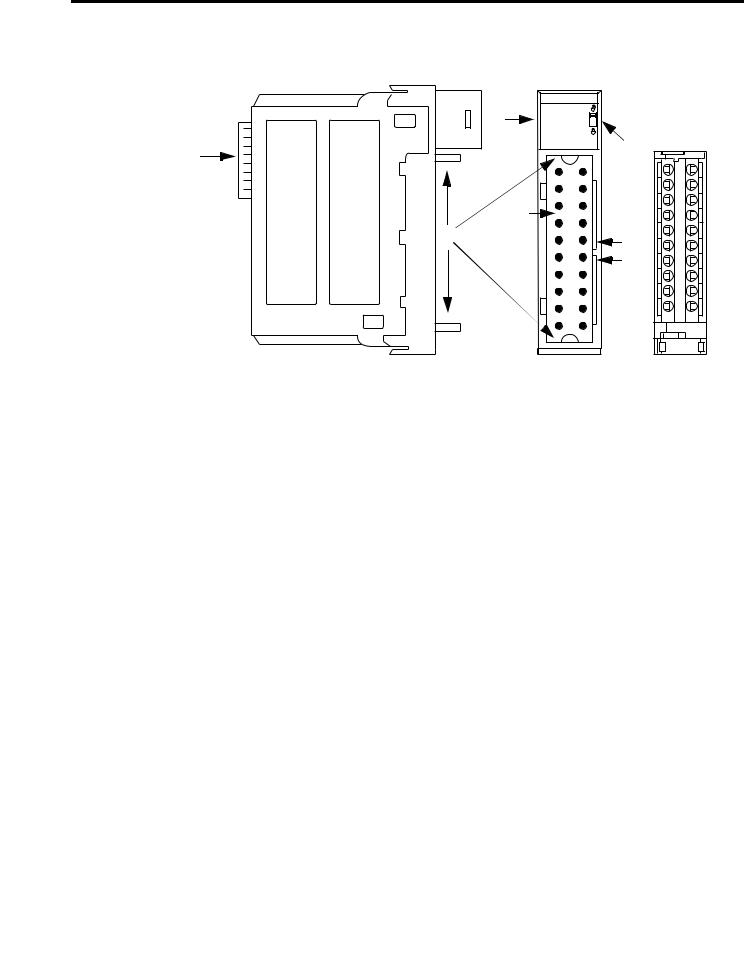
Module Components This figure shows the physical features of the ControlLogix analog I/O modules.
5 |
Removable |
|
Terminal |
||
|
||
|
Block (RTB) |
|
1 |
3 |
|
|
||
|
2 |
|
6 |
|
|
|
4 |
|
|
45118 |
|
|
# |
Physical Feature |
Description |
|
|
|
|
|
|
|
1 |
Backplane connector |
The backplane connector interface for the ControlLogix system connects the module to the ControlBus backplane. |
|
|
|
|
|
|
|
2 |
Connector pins |
Input/output, power, and grounding connections are made to the module through these pins with the use of a |
|
|
|
|
removable terminal block (RTB) or interface module (IFM). |
|
|
|
|
|
|
|
3 |
Locking tab |
The locking tab anchors the RTB or IFM cable on the module, maintaining wiring connections. |
|
|
|
|
|
|
|
4 |
Slots for keying |
Mechanically keys the RTB to prevent inadvertently making the wrong wire connections to the module. |
|
|
|||
|
|
|
|
|
|
|
5 |
Status indicators |
Indicators display the status of communication, module health, and input and output devices. Use these indicators |
|
|
|
|
to help in troubleshooting. |
|
|
|
|
|
|
|
6 |
Top and bottom guides |
Guides provide assistance in seating the RTB or IFM cable onto the module. |
|
|
|
|
|
HART Communication
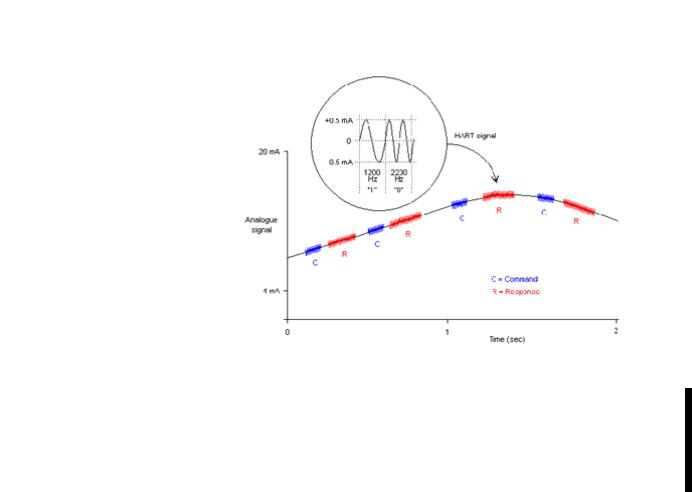
The HART field communication protocol is widely accepted in industry as a standard for digitally enhanced 4…20 mA communication with smart (microprocessor-based) field devices. A digital signal is superimposed onto the 4…20 mA current loop to provide two means of communication from the device. The 4…20 mA analog channel lets a single process variable be communicated at the fastest possible rate while the digital channel provides access to multiple process variables, data quality, and device status information. The HART protocol lets these simultaneous communication channels be used in a complementary fashion.
The modules support the HART protocol and perform these distinct operations:
•Convert to or from 4…20 mA analog signals and digital numeric values in engineering units used in the Logix controller.
•Collect dynamic process data automatically from the connected HART field device, such as temperature, pressure, flow, or valve position.
•Configure and troubleshoot the HART Field Device by using FactoryTalk AssetCentre service from your control room.
14 |
Rockwell Automation Publication 1756-UM533C-EN-P - February 2011 |
ControlLogix HART Analog I/O Modules |
Chapter 1 |
|
|
See the figure(1) that shows information about the HART protocol.
The Highway Addressable Remote Transducer (HART) protocol supports two-way digital communication, complements traditional 4…20 mA analog signals, and includes the following features:
·Predefined commands
-Common practice
-General purpose
-Device specific
·Large installed base
·Worldwide support
|
|
|
|
|
|
|
|
|
|
|
|
|
|
|
|
|
|
|
|
|
|
|
|
|
|
|
|
|
|
+0.5 mA |
|
|
|
|
|
|
|
|
|
|
|
|
|
|
|
||||
|
|
|
|
|
|
|
|
|
|
|
|
|
|
|
|
HART Signal |
|
|
|
|
|
|||
|
|
|
|
|
|
|
|
|
|
|
|
|
|
|
|
|
|
|
||||||
|
20 mA |
|
|
|
|
|
0 |
|
|
|
|
|
|
|
|
|
|
|
|
|
||||
|
|
|
|
|
|
|
|
|
|
|
|
|
|
|
|
|
|
|
|
|
|
|
||
|
|
|
|
|
|
|
|
|
|
|
|
|
|
|
|
|
|
|
|
|
|
|
|
|
|
|
|
|
|
|
0.5 mA |
|
|
|
|
|
|
|
|
|
|
|
|
|
|
|
|||
|
|
|
|
|
|
1200 |
|
2200 |
|
|
|
|
|
|
|
|
|
|
|
|||||
|
|
|
|
|
|
|
|
|
|
|
|
|
||||||||||||
|
|
|
|
|
|
|
|
|
|
Hz |
|
Hz |
|
|
|
|
|
|
|
|
|
|
|
|
|
|
|
"1" |
|
|
"0" |
|
|
|
|
|
|
|
|
|
|
|
|||||||
|
Analog |
|
|
|
|
|
|
|
|
|
|
|
|
|
|
|
|
|
|
|
|
|
|
|
|
|
|
|
|
|
|
|
|
|
|
|
|
|
|
|
|
|
|
|
|
|
|
|
|
|
Signal |
|
|
|
|
|
|
|
|
|
|
|
|
|
|
|
|
|
|
|
|
|
|
|
|
|
|
|
|
|
|
|
|
|
|
|
|
|
|
|
|
|
|
|
|
|
|
|
|
|
4 mA |
|
|
|
Analog |
|
|
|
|
|
|
|
|
|
|
|
|
|
|
|
||||
|
|
|
|
Signal |
|
|
|
|
|
|
|
|
|
|
|
|
|
|
|
|||||
|
|
|
|
|
|
|
|
|
|
|
|
|
|
|
|
|
|
|
|
|||||
|
|
|
|
|
|
|
|
|
|
|
|
|
|
|
|
|
|
|
|
|
|
|
|
|
|
|
|
|
|
|
|
|
|
|
|
|
|
|
|
|
|
|
|
|
|
|
|||
|
|
0 |
|
|
|
|
|
|
|
|
|
1 |
|
|
|
|
|
|
2 |
|||||
|
|
|
|
|
|
|
|
|
|
|
|
|
Time (seconds) |
|
||||||||||
|
|
|
|
|
|
|
|
|
|
|
|
|
|
|
|
|
|
|
|
|
|
|||
|
|
|
|
|
|
|
|
|
|
|
|
|
|
|
|
|
|
|
|
|
|
|
|
|
|
|
|
|
|
|
|
|
|
|
|
|
|
|
|
|
|
|
|
|
|
|
|
|
|
With the ControlLogix HART analog I/O modules, field device data can be accessed by both the controller and device maintenance and management software.
The ControlLogix HART analog I/O modules support Command-response communication protocol and point-to-point wiring architecture.
(1)The figure is from the HART Communication Protocol Specifications, April, 2001, Revision 6.0, HART Communication Foundation, All Rights Reserved.
Rockwell Automation Publication 1756-UM533C-EN-P - February 2011 |
15 |
Chapter 1 ControlLogix HART Analog I/O Modules
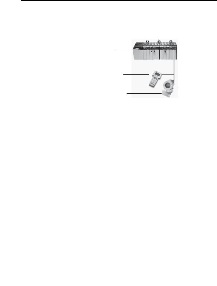
Commands can be accepted from either of two master devices. The controller is one of the master devices and continuously obtains information from the field device. The second master can typically be device maintenance, for example a handheld communicator, as shown below.
Primary Master
Secondary Master (handheld communicator as secondary master)
Slave
44219
Integrated HART Networks
Most transmitters are available with a HART protocol interface. The type of data available is dependent on the type of instrument.
An example application is a smart mass flowmeter. By using just the standard mA signal from the flowmeter it provides one field measurement - flow. By using the mA signal with HART provides additional process information. The
mA signal representing flow is still available. The HART configuration of the flowmeter can be set for primary value (PV) being mass flow, secondary value (SV) being static pressure, third value (TV) being temperature, and
fourth value (FV) being a digital representation of the mA signal.
In addition to these additional process variables, device status is also provided via HART. Instead of one process variable, the controller sees four process variables, has a check on the mA signal, and has a reading of device status. HART connectivity provides all this with no changes to the existing 4…20 mA wiring.
This HART connectivity also provides remote configuration and troubleshooting of field devices by using software, such as FactoryTalk AssetCentre or Endress+Hauser FieldCare software.
HART-enabled I/O Modules
The ControlLogix HART analog I/O modules have HART modems built in, so there is no need to install external HART multiplexors or clip on
HART modems.
16 |
Rockwell Automation Publication 1756-UM533C-EN-P - February 2011 |
ControlLogix HART Analog I/O Modules |
Chapter 1 |
|
|
Asset Management
Software
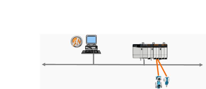
You can use the modules with asset management software. The following figure shows the use of asset management software, such as FactoryTalk AssetCentre software or Endress+Hauser FieldCare software.
Asset
Management
Software
EtherNet/IP Network
44220
Electronic Keying
The electronic keying feature automatically compares the expected module, as shown in the RSLogix 5000 I/O Configuration tree, to the physical module before I/O communication begins. You can use electronic keying to help prevent communication to a module that does not match the type and revision expected.
For each module in the I/O Configuration tree, the user-selected keying option determines if, and how, an electronic keying check is performed. Typically, three keying options are available.
•Exact Match
•Compatible Keying
•Disable Keying
|
You must carefully consider the benefits and implications of each keying option |
|
when selecting between them. For some specific module types, fewer options are |
|
available. |
|
Electronic keying is based on a set of attributes unique to each product revision. |
|
When a Logix5000 controller begins communicating with a module, this set of |
|
keying attributes is considered. |
Table 1 - Keying Attributes |
|
|
|
Attribute |
Description |
|
|
Vendor |
The manufacturer of the module, for example, Rockwell Automation/Allen-Bradley. |
|
|
Product Type |
The general type of the module, for example, communication adapter, AC drive, or digital I/O. |
|
|
Product Code |
The specific type of module, generally represented by its catalog number, for example, 1756-IB16I. |
|
|
Major Revision |
A number that represents the functional capabilities and data exchange formats of the module. Typically, although not always, a later, |
|
that is higher, Major Revision supports at least all of the data formats supported by an earlier, that is lower, Major Revision of the same |
|
catalog number and, possibly, additional ones. |
|
|
Minor Revision |
A number that indicates the module’s specific firmware revision. Minor Revisions typically do not impact data compatibility but may |
|
indicate performance or behavior improvement. |
|
|
Rockwell Automation Publication 1756-UM533C-EN-P - February 2011 |
17 |
Chapter 1 ControlLogix HART Analog I/O Modules
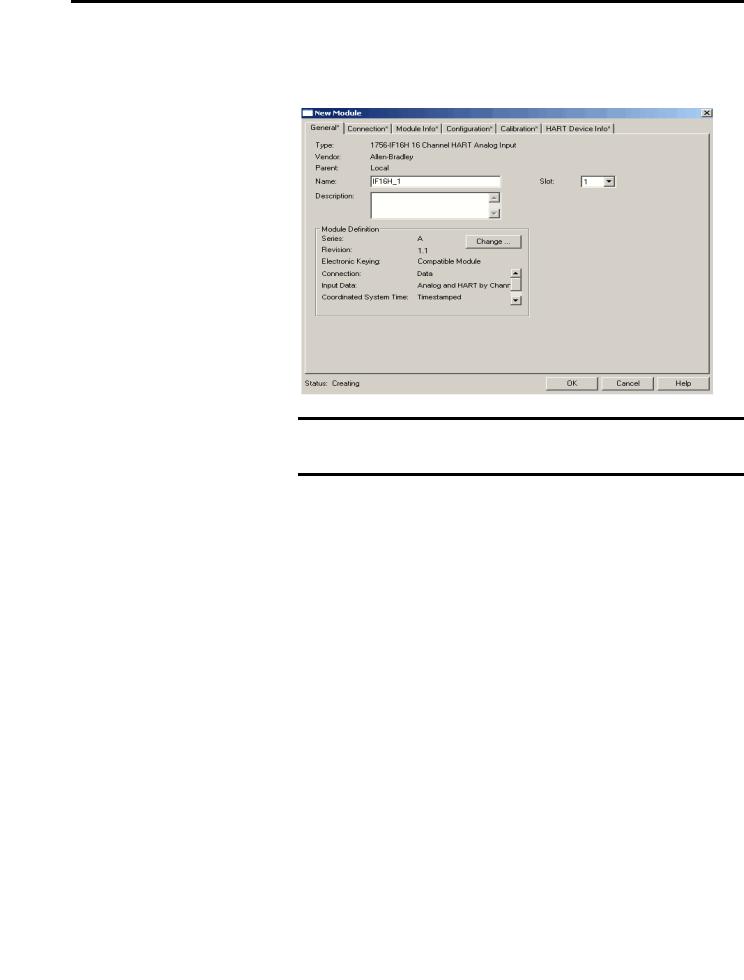
You can find revision information on the General tab of a module’s Properties dialog box.
Figure 1 - General Tab
IMPORTANT Changing electronic keying selections online may cause the I/O communication connection to the module to be disrupted and may result in a loss of data.
Exact Match
Exact Match keying requires all keying attributes, that is, Vendor, Product Type, Product Code (catalog number), Major Revision, and Minor Revision, of the physical module and the module created in the software to match precisely to establish communication. If any attribute does not match precisely, I/O communication is not permitted with the module or with modules connected through it, as in the case of a communication module.
Use Exact Match keying when you need the system to verify that the module revisions in use are exactly as specified in the project, such as for use in highlyregulated industries. Exact Match keying is also necessary to enable Automatic Firmware Update for the module via the Firmware Supervisor feature from a Logix5000 controller.
18 |
Rockwell Automation Publication 1756-UM533C-EN-P - February 2011 |
ControlLogix HART Analog I/O Modules |
Chapter 1 |
|
|
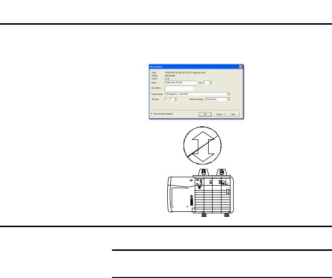
EXAMPLE In the following scenario, Exact Match keying prevents I/O communication.
The module configuration is for a 1756-IB16D module with module revision 3.1. The physical module is a 1756-IB16D module with module revision 3.2. In this case, communication is prevented because the Minor Revision of the module does not match precisely.
Module Configuration
Vendor = Allen-Bradley
Product Type = Digital Input
Module
Catalog Number = 1756-IB16D
Major Revision = 3
Minor Revision = 1
Communication is prevented.
Physical Module
Vendor = Allen-Bradley
Product Type = Digital Input
Module
Catalog Number = 1756-IB16D
Major Revision = 3
Minor Revision = 2
IMPORTANT Changing electronic keying selections online may cause the I/O Communication connection to the module to be disrupted and may result in a loss of data.
Compatible Keying
Compatible keying indicates that the module determines whether to accept or reject communication. Different module families, communication adapters, and module types implement the compatibility check differently based on the family capabilities and on prior knowledge of compatible products.
Compatible keying is the default setting. Compatible keying allows the physical module to accept the key of the module configured in the software, provided that the configured module is one the physical module is capable of emulating. The exact level of emulation required is product and revision specific.
With Compatible keying, you can replace a module of a certain Major Revision with one of the same catalog number and the same or later, that is higher, Major Revision. In some cases, the selection makes it possible to use a replacement that is a different catalog number than the original. For example, you can replace a 1756-CNBR module with a 1756-CN2R module.
Rockwell Automation Publication 1756-UM533C-EN-P - February 2011 |
19 |
Chapter 1 ControlLogix HART Analog I/O Modules
Release notes for individual modules indicate the specific compatibility details.
When a module is created, the module developers consider the module’s development history to implement capabilities that emulate those of the previous module. However, the developers cannot know future developments. Because of this, when a system is configured, we recommend that you configure the module by using the earliest, that is, lowest, revision of the physical module that you believe will be used in the system. By doing this, you can avoid the case of a physical module rejecting the keying request because it is an earlier revision than the one configured in the software.
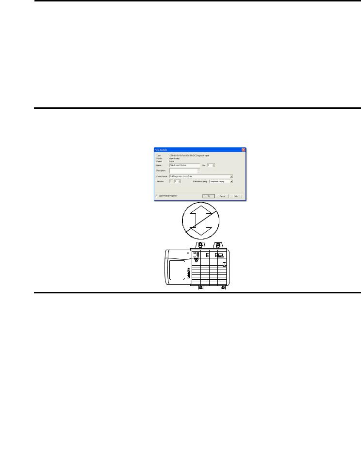
EXAMPLE In the following scenario, Compatible keying prevents I/O communication:
The module configuration is for a 1756-IB16D module with module revision 3.3. The physical module is a 1756-IB16D module with module revision 3.2. In this case, communication is prevented because the minor revision of the module is lower than expected and may not be compatible with 3.3.
Module Configuration
Vendor = Allen-Bradley
Product Type = Digital Input
Module
Catalog Number = 1756-IB16D
Major Revision = 3
Minor Revision = 3
Communication is prevented.
Physical Module
Vendor = Allen-Bradley
Product Type = Digital Input
Module
Catalog Number = 1756-IB16D
Major Revision = 3
Minor Revision = 2
20 |
Rockwell Automation Publication 1756-UM533C-EN-P - February 2011 |
ControlLogix HART Analog I/O Modules |
Chapter 1 |
|
|
EXAMPLE In the following scenario, Compatible keying allows I/O communication:
The module configuration is for a 1756-IB16D module with module revision 2.1. The physical module is a 1756-IB16D module with module revision 3.2. In this case, communication is allowed because the major revision of the physical module is higher than expected and the module determines that it is compatible with the prior major revision.
Module Configuration
Vendor = Allen-Bradley
Product Type = Digital Input
Module
Catalog Number = 1756-IB16D
Major Revision = 2
Minor Revision = 1
Communication is allowed.
Physical Module
Vendor = Allen-Bradley
Product Type = Digital Input
Module
Catalog Number = 1756-IB16D
Major Revision = 3
Minor Revision = 2
IMPORTANT Changing electronic keying selections online may cause the I/O communication connection to the module to be disrupted and may result in a loss of data.
Disabled Keying
Disabled keying indicates the keying attributes are not considered when attempting to communicate with a module. Other attributes, such as data size and format, are considered and must be acceptable before I/O communication is established. With Disabled keying, I/O communication may occur with a module other than the type specified in the I/O Configuration tree with unpredictable results. We generally do not recommend using Disabled keying.
ATTENTION: Be extremely cautious when using Disabled keying; if used incorrectly, this option can lead to personal injury or death, property damage, or economic loss.
Rockwell Automation Publication 1756-UM533C-EN-P - February 2011 |
21 |
Chapter 1 ControlLogix HART Analog I/O Modules
If you use Disabled keying, you must take full responsibility for understanding whether the module that is being used can fulfill the functional requirements of the application.
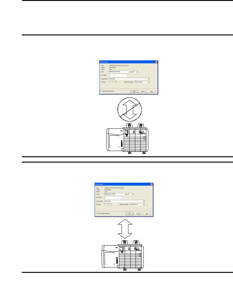
EXAMPLE In the following scenario, Disable keying prevents I/O communication:
The module configuration is for a 1756-IA16 digital input module. The physical module is a 1756-IF16 analog input module. In this case, communication is prevented because the analog module rejects the data formats that the digital module configuration requests.
Module Configuration
Vendor = Allen-Bradley
Product Type = Digital Input
Module
Catalog Number = 1756-IA16
Major Revision = 3
Minor Revision = 1
Communication is prevented.
Physical Module
Vendor = Allen-Bradley
Product Type = Analog Input
Module
Catalog Number = 1756-IF16
Major Revision = 3
Minor Revision = 2
EXAMPLE In the following scenario, Disable keying allows I/O communication:
The module configuration is for a 1756-IA16 digital input module. The physical module is a 1756-IB16 digital input module. In this case, communication is allowed because the two digital modules share common data formats.
Module Configuration
Vendor = Allen-Bradley
Product Type = Digital Input
Module
Catalog Number = 1756-IA16
Major Revision = 2
Minor Revision = 1
Communication is allowed.
Physical Module
Vendor = Allen-Bradley
Product Type = Digital Input
Module
Catalog Number = 1756-IB16
Major Revision = 3
Minor Revision = 2
22 |
Rockwell Automation Publication 1756-UM533C-EN-P - February 2011 |

ControlLogix HART Analog I/O Modules |
Chapter 1 |
|
|
Timestamping
IMPORTANT Changing electronic keying selections online may cause the I/O communication connection to the module to be disrupted and may result in a loss of data.
Controllers within the ControlLogix chassis maintain a system clock. This clock is also known as the coordinated system time (CST). You can configure your analog I/O modules to access this clock and timestamp input data or output echo data when the module multicasts to the system.
This feature provides accurate calculations between events to help you identify the sequence of events in either fault conditions or in the course of normal I/O operations. The system clock can be used between multiple modules in the same chassis.
Each module maintains a rolling timestamp that is unrelated to the coordinated system time. The rolling timestamp is a continuously running 15-bit timer that counts in milliseconds.
For input modules, whenever a module scans its channels, it also records the value of the rolling timestamp at that time. Your program can then use the last two rolling timestamp values and calculate the interval between receipt of data or the time when new data was received.
For output modules, the rolling timestamp value is updated only when new values are applied to the Digital to Analog Converter (DAC).
Rockwell Automation Publication 1756-UM533C-EN-P - February 2011 |
23 |

Chapter 1 ControlLogix HART Analog I/O Modules
Module Scaling
When using scaling, you change a quantity from one notation to another.
To scale a channel, choose two points along the module's operating range and apply corresponding low and high unit values to those points.
Scaling lets you configure the module to return data to the controller in units that match the quantity being measured. For example, the analog input module can provide the temperature in degrees Celsius or the pressure in mbar. An analog output module might have commanded values represented in % of stroke of a valve. This makes it easier to use the values in your control program than by using the raw signal value in mA.
Units like gallons, percent, mbar, psi, celsius, liters, and liters/minute are referred to as Engineering Units.
For more information about scaling, see Scaling to Engineering Units on page 98.
24 |
Rockwell Automation Publication 1756-UM533C-EN-P - February 2011 |

Chapter 2
Module Installation
Introduction
The 1756-IF8H, 1756-OF8H, and 1756-IF16H analog modules use the HART protocol with eight and 16 channels, respectively. This chapter describes basic installation procedures.
The table explains the topics discussed in this chapter.
Topic |
Page |
|
|
Environment and Enclosure |
26 |
|
|
Preventing Electrostatic Discharge |
26 |
|
|
European Hazardous Location Approval |
26 |
|
|
North American Hazardous Location Approval |
27 |
|
|
Removal and Insertion Under Power (RIUP) |
28 |
|
|
Before You Begin |
28 |
|
|
Module Accessories |
28 |
|
|
Power Requirements |
29 |
|
|
Install the Module |
30 |
|
|
Key the Removable Terminal Block/Interface Module |
31 |
|
|
Wire the Removable Terminal Block |
32 |
|
|
Ground the Module |
32 |
|
|
Wire the Module |
34 |
|
|
Removal Terminal Block Assembly and Installation |
34 |
|
|
Remove the Removable Terminal Block |
36 |
|
|
Remove the Module |
37 |
|
|
Rockwell Automation Publication 1756-UM533C-EN-P - February 2011 |
25 |
Chapter 2 Module Installation
Environment and Enclosure
Preventing Electrostatic
Discharge
ATTENTION: This equipment is intended for use in a Pollution Degree 2 industrial environment, in overvoltage Category II applications (as defined in IEC 60664-1), at altitudes up to 2000 m (6562 ft) without derating.
This equipment is considered Group 1, Class A industrial equipment according to IEC/CISPR 11. Without appropriate precautions, there may be difficulties with electromagnetic compatibility in residential and other environments due to conducted and radiated disturbances.
This equipment is supplied as open-type equipment. It must be mounted within an enclosure that is suitably designed for those specific environmental conditions that will be present and appropriately designed to prevent personal injury resulting from accessibility to live parts. The enclosure must have suitable flame-retardant properties to prevent or minimize the spread of flame, complying with a flame spread rating of 5VA, V2, V1, V0 (or equivalent) if non-metallic. The interior of the enclosure must be accessible only by the use of a tool. Subsequent sections of this publication may contain additional information regarding specific enclosure type ratings that are required to comply with certain product safety certifications.
In addition to this publication, see the following:
•Industrial Automation Wiring and Grounding Guidelines, publication 1770-4.1, for additional installation requirements
•NEMA Standard 250 and IEC 60529, as applicable, for explanations of the degrees of protection provided by enclosures
ATTENTION: This equipment is sensitive to electrostatic discharge, which can cause internal damage and affect normal operation. Follow these guidelines when you handle this equipment:
•Touch a grounded object to discharge potential static.
•Wear an approved grounding wriststrap.
•Do not touch connectors or pins on component boards.
•Do not touch circuit components inside the equipment.
•Use a static-safe workstation, if available.
•Store the equipment in appropriate static-safe packaging when not in use.
European Hazardous
Location Approval
European Zone 2 Certification
(The following applies when the product bears the EX marking.)
This equipment is intended for use in potentially explosive atmospheres as defined by European Union Directive 94/9/EC and has been found to comply with the Essential Health and Safety Requirements relating to the design and construction of Category 3 equipment intended for use in Zone 2 potentially explosive atmospheres, given in Annex II to this Directive.
Compliance with the Essential Health and Safety Requirements has been assured by compliance with EN 60079-15 and EN 60079-0.
26 |
Rockwell Automation Publication 1756-UM533C-EN-P - February 2011 |
Module Installation |
Chapter 2 |
|
|
WARNING:
• This equipment must be installed in an enclosure providing at least IP54 protection when applied in Zone 2 environments.
•This equipment shall be used within its specified ratings defined by Rockwell Automation.
•Provision shall be made to prevent the rated voltage from being exceeded by transient disturbances of more than 40% when applied in Zone 2 environments.
•This equipment must be used only with ATEX certified Rockwell Automation backplanes.
•Secure any external connections that mate to this equipment by using screws, sliding latches, threaded connectors, or other means provided with this product.
•Do not disconnect equipment unless power has been removed or the area is known to be nonhazardous.
North American Hazardous
Location Approval
The following information applies when operating this |
Informations sur l’utilisation de cet équipement en |
||||||
equipment in hazardous locations: |
environnements dangereux: |
||||||
|
|
||||||
Products marked "CL I, DIV 2, GP A, B, C, D" are suitable for use in |
Les produits marqués "CL I, DIV 2, GP A, B, C, D" ne conviennent qu'à |
||||||
Class I Division 2 Groups A, B, C, D, Hazardous Locations and |
une utilisation en environnements de Classe I Division 2 Groupes A, B, |
||||||
nonhazardous locations only. Each product is supplied with |
C, D dangereux et non dangereux. Chaque produit est livré avec des |
||||||
markings on the rating nameplate indicating the hazardous |
marquages sur sa plaque d'identification qui indiquent le code de |
||||||
location temperature code. When combining products within a |
température pour les environnements dangereux. Lorsque plusieurs |
||||||
system, the most adverse temperature code (lowest "T" number) |
produits sont combinés dans un système, le code de température le |
||||||
may be used to help determine the overall temperature code of the |
plus défavorable (code de température le plus faible) peut être utilisé |
||||||
system. Combinations of equipment in your system are subject to |
pour déterminer le code de température global du système. Les |
||||||
investigation by the local Authority Having Jurisdiction at the time |
combinaisons d'équipements dans le système sont sujettes à |
||||||
of installation. |
inspection par les autorités locales qualifiées au moment de |
||||||
|
|
|
|
l'installation. |
|||
|
|
|
|
|
|
|
|
|
|
|
EXPLOSION HAZARD |
|
|
|
RISQUE D’EXPLOSION |
|
|
|
• Do not disconnect equipment unless power |
|
|
|
• Couper le courant ou s'assurer que |
|
|
|
has been removed or the area is known to be |
|
|
|
l'environnement est classé non dangereux avant |
|
|
|
|
||||
|
|
|
nonhazardous. |
|
|
|
de débrancher l'équipement. |
|
|
|
• Do not disconnect connections to this |
|
|
|
• Couper le courant ou s'assurer que |
|
|
|
equipment unless power has been removed or |
|
|
|
l'environnement est classé non dangereux avant |
|
|
|
the area is known to be nonhazardous. Secure |
|
|
|
de débrancher les connecteurs. Fixer tous les |
|
|
|
any external connections that mate to this |
|
|
|
connecteurs externes reliés à cet équipement à |
|
|
|
equipment by using screws, sliding latches, |
|
|
|
l'aide de vis, loquets coulissants, connecteurs |
|
|
|
threaded connectors, or other means provided |
|
|
|
filetés ou autres moyens fournis avec ce produit. |
|
|
|
with this product. |
|
|
|
• La substitution de composants peut rendre cet |
|
|
|
• Substitution of components may impair |
|
|
|
|
|
|
|
|
|
|
équipement inadapté à une utilisation en |
|
|
|
|
suitability for Class I, Division 2. |
|
|
|
environnement de Classe I, Division 2. |
|
|
|
• If this product contains batteries, they must |
|
|
|
• S'assurer que l'environnement est classé non |
|
|
|
only be changed in an area known to be |
|
|
|
dangereux avant de changer les piles. |
|
|
|
nonhazardous. |
|
|
|
|
|
|
|
|
|
|
|
|
Rockwell Automation Publication 1756-UM533C-EN-P - February 2011 |
27 |
Chapter 2 Module Installation
Removal and Insertion
Under Power (RIUP)
WARNING: When you insert or remove the module while backplane power is on, an electrical arc can occur. This could cause an explosion in hazardous location installations.
Be sure that power is removed or the area is nonhazardous before proceeding. Repeated electrical arcing causes excessive wear to contacts on both the module and its mating connector. Worn contacts may create electrical resistance that can affect module operation.
ATTENTION: This equipment is not resistant to sunlight or other sources of UV radiation.
Before You Begin
IMPORTANT Before you install your module, you should have already:
•Installed and grounded a 1756 chassis and power supply.
•Ordered and received a removable terminal block (RTB) or
1492 interface module (IFM) and its components for your application.
Module Accessories
These modules mount in a ControlLogix chassis and use a separately-ordered removable terminal block (RTB) or a 1492 interface module (IFM) to connect all field-side wiring.
The ControlLogix HART analog modules use one of the following RTBs and support these IFMs.
Module |
RTBs(1) |
IFMs(2) |
|
1756-IF8H |
• 1756-TBCH 36-position cage clamp RTB |
• |
1492-ACABLExUD (current) |
|
• 1756-TBS6H 36-position spring clamp RTB |
• |
1492-ACABLExUC (voltage) |
|
|
|
|
1756-IF16H |
• 1756-TBCH 36-position cage clamp RTB |
• |
1492-ACABLExUB |
|
• 1756-TBS6H 36-position spring clamp RTB |
|
|
|
|
|
|
1756-OF8H |
• 1756-TBNH 20-position NEMA RTB |
• |
1492-ACABLExWB (current) |
|
• 1756-TBSH 20-position spring clamp RTB |
• |
1492-ACABLExWA (voltage) |
|
|
|
|
(1)Use an extended-depth cover (1756-TBE) for applications with heavy gauge wiring or requiring additional routing space.
(2)See the IFMs for the respective modules on page 192. Consult the documentation that came with it to connect all wiring.
ATTENTION: The ControlLogix system has been agency certified using only the ControlLogix RTBs (catalog numbers 1756-TBCH and 1756-TBS6H). Any application that requires agency certification of the ControlLogix system using other wiring termination methods may require application specific approval by the certifying agency.
28 |
Rockwell Automation Publication 1756-UM533C-EN-P - February 2011 |
Module Installation |
Chapter 2 |
|
|
Power Requirements
ATTENTION: To comply with the CE low voltage directive (LVD), all connected I/O must be powered from a source compliant with safety extra low voltage (SELV) or protected extra low voltage (PELV).
WARNING: Use supply wires suitable for 30 °C (86 °F) above surrounding ambient.
These modules receive power from the 1756 chassis power supply and require these two sources of power from the backplane.
Module |
Power Requirements, max |
|
|
|
|
|
|
1756-IF8H |
• 300 mA at 5.1V DC |
|
|
|
|
||
|
• 135 mA at 24V DC |
|
|
|
|
|
|
1756-IF16H |
• 200 mA at 5.1V DC |
|
|
|
• 125 mA at 24V DC |
|
|
|
|
|
|
1756-OF8H |
• 200 mA at 5.1 V DC |
|
|
|
|
||
|
• 230 mA at 24 V DC |
|
|
|
|
|
|
IMPORTANT The 1756-OF8H module requires more power than the standard 1756-OF8 module. You can have a maximum of 12 1756-OF8H modules per chassis.
ATTENTION: Personnel responsible for the application of safety-related programmable electronic systems (PES) shall be aware of the safety requirements in the application of the system and shall be trained in using the system.
Rockwell Automation Publication 1756-UM533C-EN-P - February 2011 |
29 |

Chapter 2 Module Installation
Install the Module
You can install or remove the module while chassis power is applied.
ATTENTION: The module is designed to support removal and insertion under power (RIUP). However, when you remove or insert an RTB with fieldside power applied, unintended machine motion or loss of process control can occur. Exercise extreme caution when using this feature.
1. Align the circuit board with the top and bottom chassis guides.
20861
2. Slide the module into the chassis until the module locking tabs click.
 Locking Tab
20862
30 |
Rockwell Automation Publication 1756-UM533C-EN-P - February 2011 |
Loading...