


 Loading...
User Manual
ControlLogix Configurable Flowmeter Module
Catalog Numbers 1756-CFM
Important User Information
Solid-state equipment has operational characteristics differing from those of electromechanical equipment. Safety Guidelines for the Application, Installation and Maintenance of Solid State Controls (publication SGI-1.1 available from your local Rockwell Automation® sales office or online at http://www.rockwellautomation.com/literature/) describes some important differences between solid-state equipment and hard-wired electromechanical devices. Because of this difference, and also because of the wide variety of uses for solid-state equipment, all persons responsible for applying this equipment must satisfy themselves that each intended application of this equipment is acceptable.
In no event will Rockwell Automation, Inc. be responsible or liable for indirect or consequential damages resulting from the use or application of this equipment.
The examples and diagrams in this manual are included solely for illustrative purposes. Because of the many variables and requirements associated with any particular installation, Rockwell Automation, Inc. cannot assume responsibility or liability for actual use based on the examples and diagrams.
No patent liability is assumed by Rockwell Automation, Inc. with respect to use of information, circuits, equipment, or software described in this manual.
Reproduction of the contents of this manual, in whole or in part, without written permission of Rockwell Automation, Inc., is prohibited.
Throughout this manual, when necessary, we use notes to make you aware of safety considerations.
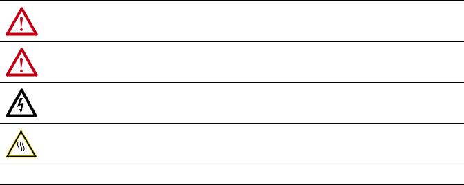
WARNING: Identifies information about practices or circumstances that can cause an explosion in a hazardous environment, which may lead to personal injury or death, property damage, or economic loss.
ATTENTION: Identifies information about practices or circumstances that can lead to personal injury or death, property damage, or economic loss. Attentions help you identify a hazard, avoid a hazard, and recognize the consequence.
SHOCK HAZARD: Labels may be on or inside the equipment, for example, a drive or motor, to alert people that dangerous voltage may be present.
BURN HAZARD: Labels may be on or inside the equipment, for example, a drive or motor, to alert people that surfaces may reach dangerous temperatures.
IMPORTANT Identifies information that is critical for successful application and understanding of the product.
Allen-Bradley, Rockwell Software, Rockwell Automation, and TechConnect are trademarks of Rockwell Automation, Inc.
Trademarks not belonging to Rockwell Automation are property of their respective companies.

Summary of Changes
New and Updated
Information
This manual contains new and updated information. Changes throughout this revision are marked by change bars, as shown to the right of this paragraph.
This table contains the changes made to this revision.
Topic |
Page |
|
|
|
|
|
|
The Gross Rate for the Prover Function has been updated. |
48 |
|
|
|
|
||
|
|
|
|
The Configurable Output Behaviors section has been added. |
58 |
|
|
|
|
||
|
|
|
|
The Attention and Warning tables have been updated. |
61 |
|
|
|
|
||
|
|
|
|
Detailed filtering information has been added to the Configurable |
122 and 124 |
|
|
|
|
||
Flowmeter Module Configuration Tags table. |
|
|
|
|
|
|
|
The Configure Output Behavior with RSLogix 5000 Version 16 and Earlier |
147 |
|
|
|
|
||
appendix has been added. |
|
|
|
|
|
|
|
Rockwell Automation Publication 1756-UM010B-EN-P - December 2011

4Summary of Changes
Notes:
Rockwell Automation Publication 1756-UM010B-EN-P - December 2011

Table of Contents
Preface
What is the Configurable Flowmeter Module?
Configurable Flowmeter
Operation in the ControlLogix
System
Configurable Flowmeter Module
Features and Operational Modes
Who Should Use This Manual. . . . . . . . . . . . . . . . . . . . . . . . . . . . . . . . . 9
Additional Resources . . . . . . . . . . . . . . . . . . . . . . . . . . . . . . . . . . . . . . . . 9
Chapter 1
What this Chapter Contains. . . . . . . . . . . . . . . . . . . . . . . . . . . . . . . . . . 11 Using a ControlLogix
CFM Module . . . . . . . . . . . . . . . . . . . . . . . . . . . . . . . . . . . . . . . . . . . . . 12 Module Features. . . . . . . . . . . . . . . . . . . . . . . . . . . . . . . . . . . . . . . . 12 Physical Features . . . . . . . . . . . . . . . . . . . . . . . . . . . . . . . . . . . . . . . 13 Typical Applications . . . . . . . . . . . . . . . . . . . . . . . . . . . . . . . . . . . . 14 Understanding Module Input Capabilities . . . . . . . . . . . . . . . . . . . . . . 15 Understanding Module Output Capabilities . . . . . . . . . . . . . . . . . . . . . 15 Using Module Identification and Status Information. . . . . . . . . . . . . . 16
Chapter 2
What This Chapter Contains . . . . . . . . . . . . . . . . . . . . . . . . . . . . . . . . . 17
Ownership . . . . . . . . . . . . . . . . . . . . . . . . . . . . . . . . . . . . . . . . . . . . . . . 19
Using RSNetWorx and RSLogix 5000 . . . . . . . . . . . . . . . . . . . . . . . . . 19
CFM Modules in Local Chassis. . . . . . . . . . . . . . . . . . . . . . . . . . . . 20
CFM Modules in Remote Chassis. . . . . . . . . . . . . . . . . . . . . . . . . . 20
Connections . . . . . . . . . . . . . . . . . . . . . . . . . . . . . . . . . . . . . . . . . . . . . . 21
Direct Connections . . . . . . . . . . . . . . . . . . . . . . . . . . . . . . . . . . . . . 21
Listen-Only Connections. . . . . . . . . . . . . . . . . . . . . . . . . . . . . . . . . 22
Configurable Flowmeter Modules in a Local Chassis . . . . . . . . . . . . . 23
Requested Packet Interval (RPI) . . . . . . . . . . . . . . . . . . . . . . . . . . . 23
Configurable Flowmeter Modules in a Remote Chassis. . . . . . . . . . . . 24
Chapter 3
What this Chapter Contains. . . . . . . . . . . . . . . . . . . . . . . . . . . . . . . . . . 25 Understanding General Module Features . . . . . . . . . . . . . . . . . . . . . . . 25 Removal and Insertion Under Power (RIUP) . . . . . . . . . . . . . . . . 26 Module Fault Reporting . . . . . . . . . . . . . . . . . . . . . . . . . . . . . . . . . 26 Fully Software Configurable . . . . . . . . . . . . . . . . . . . . . . . . . . . . . . 26 Electronic Keying . . . . . . . . . . . . . . . . . . . . . . . . . . . . . . . . . . . . . . 27 Producer/Consumer Model . . . . . . . . . . . . . . . . . . . . . . . . . . . . . . 33 Module Status Information . . . . . . . . . . . . . . . . . . . . . . . . . . . . . . . 34 Configurable Flowmetering Channels . . . . . . . . . . . . . . . . . . . . . . 34 Flowmeter Inputs. . . . . . . . . . . . . . . . . . . . . . . . . . . . . . . . . . . . . . . 34 Gate Inputs . . . . . . . . . . . . . . . . . . . . . . . . . . . . . . . . . . . . . . . . . . . 34 User-Defined Preset and Rollover Values . . . . . . . . . . . . . . . . . . . 35 Current-Sourcing Outputs. . . . . . . . . . . . . . . . . . . . . . . . . . . . . . . . 35
Rockwell Automation Publication 1756-UM010B-EN-P - December 2011

6Table of Contents
Installing the Configurable
Flowmeter Module
Choosing an Operational Mode . . . . . . . . . . . . . . . . . . . . . . . . . . . . . . 35 Operating in High Resolution Frequency Mode . . . . . . . . . . . . . . . . . 36 Terminal Usage in High Resolution Frequency Mode. . . . . . . . . . 37 Output Operation in Frequency Mode. . . . . . . . . . . . . . . . . . . . . . 37 Module Features Used in High Resolution Frequency Mode . . . . 38 Alarms in High Resolution Frequency Mode. . . . . . . . . . . . . . . . . 40 Sample Configuration for High Resolution Frequency Mode. . . . 40 Operating in Totalizer Mode . . . . . . . . . . . . . . . . . . . . . . . . . . . . . . . . . 41 Nonresettable Totalizer . . . . . . . . . . . . . . . . . . . . . . . . . . . . . . . . . . 41 Terminal Usage in Totalizer Mode . . . . . . . . . . . . . . . . . . . . . . . . . 41 Output Operation in Totalizer Mode . . . . . . . . . . . . . . . . . . . . . . . 41 Using the Totalizer Mode Prover Function . . . . . . . . . . . . . . . . . . . . . 42 Using a Prover . . . . . . . . . . . . . . . . . . . . . . . . . . . . . . . . . . . . . . . . . 43 Features Available with the Prover Function . . . . . . . . . . . . . . . . . 44 Alarms with the Prover Function . . . . . . . . . . . . . . . . . . . . . . . . . . 49 Sample Configuration for Totalizer Mode Prover Function . . . . . 49 Using the Totalizer Mode Filler Function. . . . . . . . . . . . . . . . . . . . . . . 50 Trickle Function for Totalizer Mode . . . . . . . . . . . . . . . . . . . . . . . 51
Configurable Features Available with the
Totalizer Mode Filler Function . . . . . . . . . . . . . . . . . . . . . . . . . . . . 52 Alarms with the Filler Function . . . . . . . . . . . . . . . . . . . . . . . . . . . 57 Sample Configuration for Totalizer Mode Filler Function . . . . . . 57 Configurable Output Behaviors . . . . . . . . . . . . . . . . . . . . . . . . . . . . . . 58 How To Enable Output Behavior Configuration . . . . . . . . . . . . . 59
Chapter 4
What this Chapter Contains. . . . . . . . . . . . . . . . . . . . . . . . . . . . . . . . . . 61 Power Requirements . . . . . . . . . . . . . . . . . . . . . . . . . . . . . . . . . . . . . . . 63 Installing the Module . . . . . . . . . . . . . . . . . . . . . . . . . . . . . . . . . . . . . . . 64 Keying the Removable Terminal Block/Interface Module . . . . . . . . . 65 Key the Module . . . . . . . . . . . . . . . . . . . . . . . . . . . . . . . . . . . . . . . . 65 Key the RTB/IFM. . . . . . . . . . . . . . . . . . . . . . . . . . . . . . . . . . . . . . 66 Wiring the Removable Terminal Block. . . . . . . . . . . . . . . . . . . . . . . . . 66 Connect Grounded End of the Cable. . . . . . . . . . . . . . . . . . . . . . . 67 Connect Ungrounded End of the Cable. . . . . . . . . . . . . . . . . . . . . 67 Connect Wires to the RTBs . . . . . . . . . . . . . . . . . . . . . . . . . . . . . . 68 Wiring the Module . . . . . . . . . . . . . . . . . . . . . . . . . . . . . . . . . . . . . . . . . 69 Standard Flowmeter Wiring Example. . . . . . . . . . . . . . . . . . . . . . . 70 Standard Prover/Detector Wiring Example. . . . . . . . . . . . . . . . . . 71 Standard Output Wiring Example . . . . . . . . . . . . . . . . . . . . . . . . . 72 Assembling the Removable Terminal Block and Housing. . . . . . . . . . 73 Installing the Removable Terminal Block on the Module . . . . . . . . . . 73 Removing the Removable Terminal Block from the Module . . . . . . . 74 Removing the Module . . . . . . . . . . . . . . . . . . . . . . . . . . . . . . . . . . . . . . 76
Rockwell Automation Publication 1756-UM010B-EN-P - December 2011

Table of Contents |
7 |
|
|
Configuring the Configurable
Flowmeter Module
Troubleshooting the Configurable
Flowmeter Module
Software Configuration Tags
Schematics
Chapter 5
What this Chapter Contains. . . . . . . . . . . . . . . . . . . . . . . . . . . . . . . . . . 77 Using this Chapter . . . . . . . . . . . . . . . . . . . . . . . . . . . . . . . . . . . . . . . . . 78 Overview of the Configuration Process . . . . . . . . . . . . . . . . . . . . . . . . 78 Creating a New Module . . . . . . . . . . . . . . . . . . . . . . . . . . . . . . . . . . . . . 80 Communications Format. . . . . . . . . . . . . . . . . . . . . . . . . . . . . . . . . 82 Electronic Keying . . . . . . . . . . . . . . . . . . . . . . . . . . . . . . . . . . . . . . 82 Using the Default Configuration . . . . . . . . . . . . . . . . . . . . . . . . . . . . . . 83 Altering the Default Configuration . . . . . . . . . . . . . . . . . . . . . . . . . . . . 84 Accessing the Tags . . . . . . . . . . . . . . . . . . . . . . . . . . . . . . . . . . . . . . . . . 85 Changing Configuration Information at the Tags . . . . . . . . . . . . . . . . 86 Configurable Features . . . . . . . . . . . . . . . . . . . . . . . . . . . . . . . . . . . 86 Downloading Configuration Data. . . . . . . . . . . . . . . . . . . . . . . . . . . . . 87 Changing Configuration During CFM Module Operation . . . . . . . . . 88 Using Ladder Logic . . . . . . . . . . . . . . . . . . . . . . . . . . . . . . . . . . . . . 88 Using Message Instructions . . . . . . . . . . . . . . . . . . . . . . . . . . . . . . . . . . 89 Processing Real-Time Control and Module Services . . . . . . . . . . . 89 One Service Performed Per Instruction . . . . . . . . . . . . . . . . . . . . . 89 Creating a New Tag . . . . . . . . . . . . . . . . . . . . . . . . . . . . . . . . . . . . . . . . 90 Enter Message Configuration . . . . . . . . . . . . . . . . . . . . . . . . . . . . . 92 Configuring CFM Modules in a Remote Chassis . . . . . . . . . . . . . . . . . 95 Sample Configuration for High Resolution Frequency Mode . . . . . . . 97 Sample Configuration for Totalizer Mode Prover Function . . . . . . . 101 Sample Configuration for Totalizer Mode Filler Function . . . . . . . . 108
Appendix A
What this Appendix Contains . . . . . . . . . . . . . . . . . . . . . . . . . . . . . . . 115 Using the Status Indicators . . . . . . . . . . . . . . . . . . . . . . . . . . . . . . . . . 115 Using RSLogix 5000 to Troubleshoot Your Module . . . . . . . . . . . . . 117 Determining Fault Type . . . . . . . . . . . . . . . . . . . . . . . . . . . . . . . . 118 Using Error Codes. . . . . . . . . . . . . . . . . . . . . . . . . . . . . . . . . . . . . 119
Appendix B
. . . . . . . . . . . . . . . . . . . . . . . . . . . . . . . . . . . . . . . . . . . . . . . . . . . . . . . . 121
Appendix C
What This Appendix Contains . . . . . . . . . . . . . . . . . . . . . . . . . . . . . . 137
Input Circuits . . . . . . . . . . . . . . . . . . . . . . . . . . . . . . . . . . . . . . . . . . . . 137
Flowmeter Inputs. . . . . . . . . . . . . . . . . . . . . . . . . . . . . . . . . . . . . . 137
Gate Inputs . . . . . . . . . . . . . . . . . . . . . . . . . . . . . . . . . . . . . . . . . . 138
Output Circuits. . . . . . . . . . . . . . . . . . . . . . . . . . . . . . . . . . . . . . . . . . . 139
Discrete Outputs . . . . . . . . . . . . . . . . . . . . . . . . . . . . . . . . . . . . . . 139
Rockwell Automation Publication 1756-UM010B-EN-P - December 2011

8Table of Contents
Frequency Accuracy
Configure Output Behavior with RSLogix 5000 Version 16 and Earlier
Appendix D
Frequency Accuracy in High Resolution
Frequency Mode. . . . . . . . . . . . . . . . . . . . . . . . . . . . . . . . . . . . . . . . . . 141
Calculate Frequency Accuracy. . . . . . . . . . . . . . . . . . . . . . . . . . . . 141
Frequency Accuracy in Totalizer Mode . . . . . . . . . . . . . . . . . . . . . . . 143
Calculate Frequency Accuracy. . . . . . . . . . . . . . . . . . . . . . . . . . . . 143
Appendix E
Configure the 1756-CFM for Use in a New Application. . . . . . . 148 Configure a 1756-CFM for Use in an Existing Application . . . . 152
Glossary . . . . . . . . . . . . . . . . . . . . . . . . . . . . . . . . . . . . . . . . . . . . . . . . . . . . . . . . |
157 |
Index . . . . . . . . . . . . . . . . . . . . . . . . . . . . . . . . . . . . . . . . . . . . . . . . . . . . . . . . |
161 |
Rockwell Automation Publication 1756-UM010B-EN-P - December 2011

Preface
Who Should Use
This Manual
Additional Resources
This manual describes how to install, configure, and troubleshoot your ControlLogix® Configurable Flowmeter module.
You must be able to program and operate an Allen-Bradley® ControlLogix controller to efficiently use your Configurable Flowmeter module.
These documents contain additional information concerning related products from Rockwell Automation.
Resource |
Description |
|
|
1756 ControlLogix I/O Technical Data, |
Provides specifications for the |
publication 1756-TD002 |
ControlLogix controllers, I/O modules, |
|
specialty modules, chassis, power |
|
supplies and accessories. |
|
|
ControlLogix System User Manual, |
Detailed description of how to use your |
publication 1756-UM001 |
ControlLogix operating system. |
|
|
ControlLogix Digital I/O Modules User |
Detailed description of how to install and |
Manual, publication1756-UM058 |
use ControlLogix digital I/O Modules. |
|
|
ControlLogix Analog I/O Modules User |
Detailed description of how to install and |
Manual, publication 1756-UM009 |
use ControlLogix analog I/O Modules. |
|
|
ControlLogix High-speed Counter Module |
Detailed description of how to install and |
Installation Instructions, publication |
use the ControlLogix High-speed Counter |
1756-IN018 |
Module. |
|
|
Industrial Automation Wiring and Grounding |
Provides general guidelines for installing |
Guidelines, publication 1770-4.1 |
a Rockwell Automation industrial system. |
|
|
Product Certifications website, |
Provides declarations of conformity, |
http://www.ab.com |
certificates, and other certification |
|
details. |
|
|
You can view or download publications at http:/www.rockwellautomation.com/literature/. To order paper copies of technical documentation, contact your local Allen-Bradley distributor or Rockwell Automation sales representative.
Rockwell Automation Publication 1756-UM010B-EN-P - December 2011

10 Preface
Notes:
Rockwell Automation Publication 1756-UM010B-EN-P - December 2011
Chapter 1
What is the Configurable Flowmeter Module?
What this Chapter Contains |
This chapter describes the ControlLogix Configurable Flowmeter (1756-CFM) |
||
|
module. It also describes what you must know and do before using the |
||
|
module. |
|
|
|
|
|
|
|
Topic |
Page |
|
|
|
|
|
|
Using a ControlLogix CFM Module |
12 |
|
|
|
|
|
|
Understanding Module Input Capabilities |
15 |
|
|
|
|
|
|
Understanding Module Output Capabilities |
15 |
|
|
|
|
|
|
Using Module Identification and Status |
16 |
|
Information
The ControlLogix CFM module is an intelligent I/O module that performs high-speed flowmetering for industrial applications. The CFM module is a single-slot module that interfaces between a Logix controller and external I/O devices.
The module interfaces with the following output types:
Magnetic Pickup
TTL
Preamps
Rockwell Automation Publication 1756-UM010B-EN-P - December 2011
12 What is the Configurable Flowmeter Module?
Using a ControlLogix
CFM Module
ControlLogix CFM modules mount in a ControlLogix chassis and use a Removable Terminal Block (RTB) or a Bulletin 1492 Interface Module cable that connects to an IFM to connect all field-side wiring.
Before you install and use your module you should have already:
installed and grounded a 1756 chassis and power supply. To install these products, refer to the ControlLogix Chassis and Power Supplies Installation Instructions, publication 1756-IN005.
ordered and received an RTB or IFM and its components for your application.
IMPORTANT RTBs and IFMs are not included with your module.
Module Features
The following are some of the features available on the ControlLogix CFM module that allow greater system applicability.
2 Configurable Flowmetering channels
Flowmeter inputs
Gate inputs
2 current-sourcing outputs
Removal and insertion under power
CE marked
UL listed
CSA certified for Class I Division 2 hazardous locations
For a complete listing and detailed explanation of all the features available on the ControlLogix CFM module, see Configurable Flowmeter Module Features and Operational Modes on page 25.
Rockwell Automation Publication 1756-UM010B-EN-P - December 2011
What is the Configurable Flowmeter Module? |
13 |
|
|
ControlLogix backplane connector
Physical Features
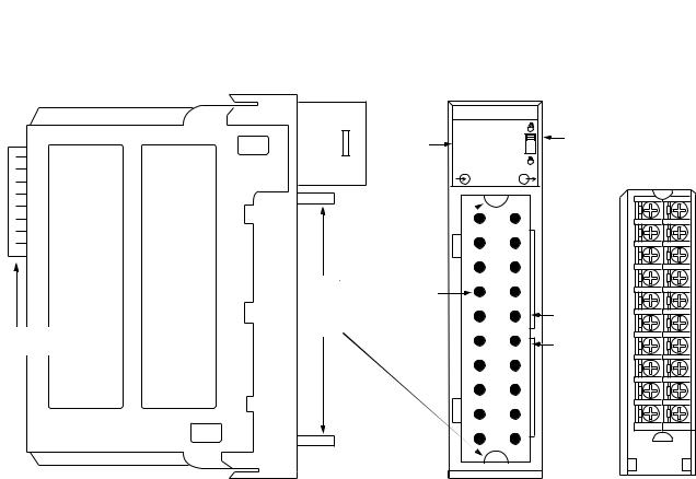
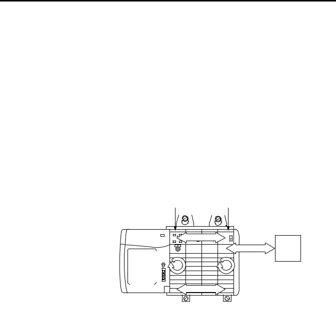
|
METERING |
|
||||
Indicators |
F |
Z |
F |
Z |
|
Locking tab |
0 |
0 |
1 |
1 |
O |
||
|
O |
O |
|
|
K |
|
|
0 |
1 |
|
|
|
|
|
|
DC I/O |
|
Removable Terminal Block |
||
Top and |
Connector pins |
|
bottom |
||
Slots for |
||
guides |
||
|
keying the |
|
|
RTB |
40200-M
ControlLogix backplane connector - The backplane connector interface for the ControlLogix system connects the module to the ControlLogix backplane.
Connectors pins - Input/output, power and grounding connections are made to the module through these pins with the use of an RTB or IFM.
Locking tab - The locking tab anchors the RTB or IFM cable on the module, maintaining wiring connections.
Slots for keying - Mechanically keys the RTB to prevent inadvertently making the wrong wire connections to your module.
Status indicators - Indicators display the status of communication, module health and input/output devices. Use these indicators to help in troubleshooting.
Top and bottom guides - Guides provide assistance in seating the RTB or IFM cable onto the module.
Rockwell Automation Publication 1756-UM010B-EN-P - December 2011
14 What is the Configurable Flowmeter Module?
Typical Applications
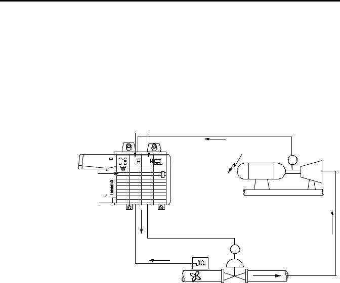
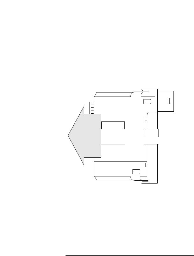
You can use the CFM module in power management, automotive, food and beverage, and oil and gas industries for various flow and/or turbine metering applications.
This figure shows a CFM module in a turbine shaft speed monitoring application. In this example, the 1756-CFM module is operating in high resolution frequency mode. Other examples are shown in Chapter 3 to reflect the various operational modes available on the 1756-CFM module.
1756-CFM |
1756-OF6VI |
|
|
|
|
|
Shaft speed |
|
Shaft |
|
|
|
encoder |
|
|
|
|
|
|
Logix controller |
|
|
Generator |
Turbine |
|
Electricity |
|
|
|
The controller |
|
|
|
|
|
|
|
|
|
monitors shaft |
|
|
|
|
speed, performs |
|
|
|
|
PID calculations |
|
|
|
|
and adjusts valve |
|
|
|
|
by a 1756-OF6VI |
|
|
|
|
analog output |
|
|
|
|
module. |
|
|
|
|
|
|
Pulse output |
CV |
|
|
|
|
|
|
Monitors fuel flow |
Fuel |
|
|
|
and total gallons |
|
|
||
|
|
|
||
|
|
|
|
42731 |
For a detailed explanation of how the CFM module works with other portions of a ControlLogix control system, see Chapter 2, Configurable Flowmeter Operation in the ControlLogix System.
Rockwell Automation Publication 1756-UM010B-EN-P - December 2011

What is the Configurable Flowmeter Module? |
15 |
|
|
Understanding Module
Input Capabilities
Understanding Module
Output Capabilities
The CFM module accepts input for up to two channels (mode dependent). Each of the input channels can connect to:
Magnetic Pickup - 50mV trigger
TTL output - 1.3V trigger
Preamp outputs - 4V trigger
You configure the CFM module’s two input channels for your specific application(s). Each input channel has two input selections:
Flowmeter Input (F0 & F1) - Connect input device to this input.
Gate Input (Z0 & Z1) - Accepts 4-40V DC input pulses from open collectors or external contact closures. These inputs are used in Totalizer mode to:
–interface to a prover when a prover is enabled.
The CFM module has two assignable outputs. These outputs are designed for applications that require fast response. The outputs:
are electrically fused/current limited to 4A; the total output combination is limited to 7A.
can be assigned to any input channel with user-defined trigger parameter (see Table 1).
are current sourcing at 10-31.2V DC (1A maximum per output).
must be connected to an external power supply.
may be forced ON or OFF by the program.
|
You can assign both outputs to a given channel; however, |
|
IMPORTANT |
||
you cannot use the same output with two different |
||
|
||
|
||
|
channels. |
|
|
||
Table 1 - Assign the CFM Module’s Outputs |
||
In this operational mode |
You can assign outputs that are |
|
configured to trigger |
|
|
Totalizer |
Frequency (acceleration) |
|
Prover status |
|
Fill control |
|
|
High-Resolution Frequency |
Frequency |
|
Frequency rate of change (acceleration) |
|
|
Rockwell Automation Publication 1756-UM010B-EN-P - December 2011

16 What is the Configurable Flowmeter Module?
Using Module
Identification and Status
Information
Each ControlLogix CFM module maintains specific identification information that separates it from all other modules. This information assists you in tracking all the components of your system.
For example, you can track module identification information to be aware of exactly what modules are located in any ControlLogix rack at any time. While retrieving module identity, you can also retrieve the module’s status.
Each module maintains the following information:
Table 2 - Module Identification and Status Information
Module Identification |
Description |
|||
|
|
|
||
Product Type |
|
Module’s product type, such as Digital I/O or |
||
|
|
Analog I/O module |
||
|
|
|
||
Catalog Code |
|
Module’s catalog number |
||
|
|
|
||
Major Revision |
|
Module’s major revision number |
||
|
|
|
||
Minor Revision |
|
Module’s minor revision number |
||
|
|
|
||
Status |
|
Module’s status. Returns the following information: |
||
|
|
Controller ownership (if any) |
||
|
|
Whether module has been configured |
||
|
|
Device Specific Status, such as: |
||
|
|
|
Self-Test |
|
|
|
Flash update in progress |
||
|
|
|
Communications fault |
|
|
|
Not owned (outputs in program mode) |
||
|
|
Internal fault (need flash update) |
||
|
|
|
Run mode |
|
|
|
Program mode (output mods only) |
||
|
|
Minor recoverable fault |
||
|
|
Minor unrecoverable fault |
||
|
|
Major recoverable fault |
||
|
|
Major unrecoverable fault |
||
|
|
|
||
Vendor ID |
|
Module manufacturer vendor, for example Allen-Bradley |
||
|
|
|
||
Serial Number |
|
Module serial number |
||
|
|
|||
Length of ASCII Text String |
Number of characters in module’s text string |
|||
|
|
|
||
ASCII Text String |
|
Number of characters in module’s text string |
||
|
|
|
||
|
|
|||
|
You must perform a WHO service to retrieve this |
|||
IMPORTANT |
||||
information. |
|
|||
|
|
|||
|
|
|||
|
|
|
|
|
Rockwell Automation Publication 1756-UM010B-EN-P - December 2011

Chapter 2
Configurable Flowmeter Operation in
the ControlLogix System
What This Chapter Contains |
This chapter describes how the CFM module works within the ControlLogix |
||
|
system. |
|
|
|
|
|
|
|
Topic |
Page |
|
|
|
|
|
|
Ownership |
19 |
|
|
|
|
|
|
Using RSNetWorx and RSLogix 5000 Software |
19 |
|
|
|
|
|
|
Connections |
21 |
|
|
|
|
|
|
Configurable Flowmeter Modules in a Local Chassis |
23 |
|
|
|
|
|
|
Requested Packet Interval (RPI) |
23 |
|
|
|
|
|
|
Configurable Flowmeter Modules in a Remote Chassis |
24 |
|
|
|
|
|
|
Listen-Only Connections |
22 |
|
|
|
|
|
In traditional industrial applications, controllers poll Flowmeter modules to obtain their status. Controllers also send commands to the Flowmeter modules. Retrieving Flowmeter status and sending commands occurs during the normal I/O program scan.
ControlLogix CFM modules do not follow the traditional operational manner. Instead, they use the Producer/Consumer Model (see page 33 for more information) to produce data without having been polled by a controller first.
Rockwell Automation Publication 1756-UM010B-EN-P - December 2011
18 Configurable Flowmeter Operation in the ControlLogix System
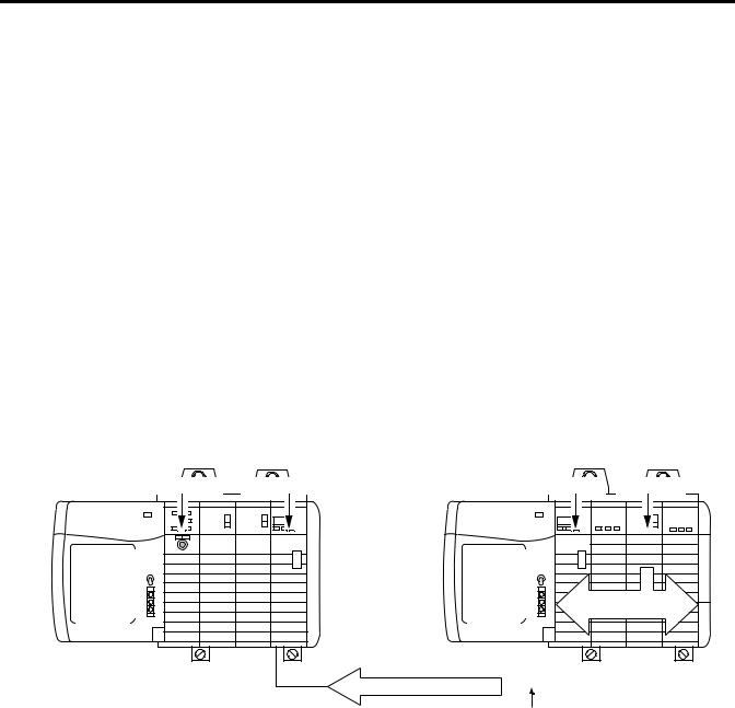
1756-CFM modules follow these basic operational steps, as shown in Figure 2.
1.The Logix controller establishes a connection to the CFM module and downloads configuration via ladder logic and message instructions.
2.Flowmeters transmit input signals to the CFM module.
3.The 1756-CFM module calculates volume from accumulated pulse counts as engineering units.
4.Rather than being scanned by an owner-controller, the 1756-CFM module periodically multicasts its status to the controller. (see Requested Packet Interval (RPI) on page 23.) The 1756-CFM module also multicasts its status to controllers connected by a listen-only connection (page 22).
5.The Logix owner-controller processes the data it received from the 1756-CFM module and returns the appropriate data.
Figure 2 - 1756-CFM Basic Operational Steps
Logix controller |
|
1756-CFM |
||
|
|
|
|
|
|
1 |
Input |
|
2 |
|
|
device |
|
|
|
|
5 |
3 |
|
|
4 |
42732 |
|
|
|
A 1756-CFM module’s communication, or multicasting, |
|
IMPORTANT |
||
behavior varies depending upon whether it operates in the |
||
|
||
|
||
|
local chassis or in a remote chassis. The following sections |
|
|
detail the differences in data transfers between these |
|
|
set-ups. |
|
|
|
Rockwell Automation Publication 1756-UM010B-EN-P - December 2011

Configurable Flowmeter Operation in the ControlLogix System |
19 |
|
|
Ownership
Using RSNetWorx and
RSLogix 5000 Software
Every CFM module in the ControlLogix system must be owned by a Logix5550® Controller. The owner-controller:
stores configuration data for every CFM module that it owns.
can be local or remote in regard to the I/O module’s position.
sends configuration data to the CFM module to define the module’s behavior within the control system.
Each CFM module continuously maintains communication with its owner during normal operation. When connections are severed or compromised, the CFM module performs as configured, either setting all outputs to reset (ON or OFF) or continuous operations.
Other controllers may also listen to the CFM module (while another controller owns the module) through a listen-only connection. For more information on listen-only connections, see page 22.
The I/O configuration portion of RSLogix™ 5000 software generates configuration data structures and tags for that CFM module, whether the module is located in a local or remote chassis. A remote chassis, also known as networked, contains the CFM module but not the module’s owner-controller.
After creating the CFM module, you can write specific configuration in the module’s data structures; you must access the module tags to change information in the data structures. This process is explained in detail in Chapter 5, Configuring the Configurable Flowmeter Module.
|
Application-specific configuration data is transferred to the |
|
IMPORTANT |
||
controller during the program download and sent to the |
||
|
||
|
||
|
CFM module during the initial power-up. After CFM |
|
|
module operation has begun, you must use ladder logic and |
|
|
message instructions to make configuration changes. |
|
|
|
Rockwell Automation Publication 1756-UM010B-EN-P - December 2011

20 Configurable Flowmeter Operation in the ControlLogix System
CFM Modules in Local Chassis
CFM modules in the same chassis as the owner-controller are ready to run as soon as the configuration data has been downloaded.
CFM Modules in Remote Chassis
You must run RSNetWorx™ software to enable CFM modules in the networked chassis. Running RSNetWorx software transfers configuration data to networked modules and establishes a Network Update Time (NUT) for ControlNet. The NUT is compliant with the desired communications options specified for each module during configuration.
Follow these general guidelines when configuring CFM modules:
1.Configure all CFM modules for a given controller using RSLogix 5000 software and download that information to the controller.
2.If the CFM configuration data references a module in a remote chassis, run RSNetWorx software.
|
RSNetWorx software must be run whenever a new |
|
IMPORTANT |
||
module is added to a networked chassis. When a module is |
||
|
||
|
||
|
permanently removed from a remote chassis, we |
|
|
recommend that RSNetWorx software be run to optimize |
|
|
the allocation of network bandwidth. |
|
|
|
Rockwell Automation Publication 1756-UM010B-EN-P - December 2011
Configurable Flowmeter Operation in the ControlLogix System |
21 |
|
|
Connections
Logix controllers make connections to 1756-CFM modules to exchange data. The controller can make either of the following connections to a 1756-CFM module:
Direct Connections - Only one controller can make this connection to a CFM module.
Listen-Only Connections - Multiple controllers can make this connection to a CFM module simultaneously.
Direct Connections
A direct connection is a real-time data transfer link between the controller and the device that occupies the slot that the configuration data references. When module configuration data is downloaded to an owner-controller, the controller attempts to establish a direct connection to each of the modules referenced by the data. One of the following events occurs:
If the data is appropriate to the module found in the slot, a connection is made and operation begins.
If the configuration data is not appropriate, the data is rejected and an error message displays in the software. In this case, the configuration data can be inappropriate for any of a number of reasons. For example, a module’s configuration data may be appropriate except for a mismatch in electronic keying that prevents normal operation.
The controller maintains and monitors its connection with a module. Any break in the connection, such as removal of the module from the chassis while under power, causes the controller to set fault status bits in the data area associated with the module. The RSLogix 5000 software may monitor this data area to announce the modules’ failures.
|
The typical Logix controller can make and maintain up to |
|
IMPORTANT |
||
250 connections. Each 1756-CFM module requires 1 |
||
|
||
|
||
|
connection. |
|
|
|
Rockwell Automation Publication 1756-UM010B-EN-P - December 2011

22 Configurable Flowmeter Operation in the ControlLogix System
Listen-Only Connections
Any controller in the system can listen to the data from any CFM module even if the controller does not own the module (in other words, it does not have to hold the module’s configuration data to listen to the module).
During the CFM module creation process in RSLogix 5000 software, you can specify the ‘Listen-Only’ Communication Format. For more information on Communication Format, see page 82.
Choosing ‘Listen-Only’ mode allows the controller and module to establish communications without the controller sending any configuration data. In this instance, another controller owns the CFM module.
|
Controllers using the Listen-Only mode continue to receive |
|
IMPORTANT |
||
data multicast from the CFM module as long as a |
||
|
||
|
||
|
connection between an owner and CFM module is |
|
|
maintained. |
If the connection between all owners and the CFM module is broken, the module stops multicasting data and connections to all ‘Listening controllers’ are also broken.
Rockwell Automation Publication 1756-UM010B-EN-P - December 2011
Configurable Flowmeter Operation in the ControlLogix System |
23 |
|
|
Configurable Flowmeter
Modules in a Local Chassis
CFM modules multicast their data periodically. Multicast frequency depends on the options chosen during configuration and where in the control system the module physically resides. The data consumer (an owner-controller) is responsible for knowing that the format of the new data is integers.
Requested Packet Interval (RPI)
This configurable parameter instructs the module to multicast its channel and status data to the local chassis backplane at specific time intervals.
The RPI instructs the module to multicast the current contents of its on-board memory when the RPI expires, (i.e. the module does not update its channels prior to the multicast) as shown in this figure.
On-Board Memory
Status Data
Flowmeter 0
Flowmeter 1
Ch 0 |
Ch 1 |
41361
|
You set the RPI value during the initial module |
|
IMPORTANT |
||
configuration and can adjust it the controller is in Program |
||
|
||
|
||
|
mode. |
|
|
The minimum RPI is determined by channel usage. For |
|
|
each channel using High Resolution Frequency mode, add |
|
|
5 ms to the minimum RPI. For each channel using |
|
|
Totalizer Mode, add 50 ms to the minimum RPI. |
For example, if one channel uses High Resolution Frequency mode and the other goes unused, the minimum RPI = 5 ms. If one channel uses High Resolution Frequency mode and the other uses Totalizer mode, the minimum RPI = 55 ms.
Rockwell Automation Publication 1756-UM010B-EN-P - December 2011
24 Configurable Flowmeter Operation in the ControlLogix System
Configurable Flowmeter
Modules in a Remote
Chassis
If an CFM module resides in a networked chassis, the role of the RPI changes slightly with respect to getting data to the owner.
The RPI not only defines when the module multicasts data within its own chassis (as described in the previous section), but also determines how often the owner-controller will receive it over
the network.
When an RPI value is specified for an CFM module in a remote chassis, in addition to instructing the module to multicast data within its own chassis, the RPI also “reserves” a spot in the stream of data flowing across the ControlNet network.
The timing of this “reserved” spot may or may not coincide with the exact value of the RPI, but the control system guarantees that the owner controller receives data at least as often as the specified RPI.
See Figure 2 for a better understanding of the data flow with a CFM module in a remote chassis.
Figure 2 - CFM Module in Remote Chassis with RPI Reserving a Spot in Flow of Data
Owner controller |
ControlNet Bridge module |
ControlNet Bridge module |
CFM module |
Data in remote chassis |
at the RPI rates |
CFM data at least as often as RPI 
ControlNet |
40947 |
|
Rockwell Automation Publication 1756-UM010B-EN-P - December 2011

Chapter 3
Configurable Flowmeter Module Features
and Operational Modes
What this Chapter Contains
Understanding General
Module Features
This chapter describes the ControlLogix Configurable Flowmeter module’s features and operational modes.
Topic |
Page |
|
|
Understanding General Module Features |
25 |
|
|
Electronic Keying |
27 |
|
|
Choosing an Operational Mode |
35 |
|
|
Operating in High Resolution Frequency Mode |
36 |
|
|
Operating in Totalizer Mode |
41 |
|
|
Using the Totalizer Mode Prover Function |
42 |
|
|
Using the Totalizer Mode Filler Function |
50 |
|
|
Configurable Output Behaviors |
58 |
|
|
This chapter only provides a general description of each feature, whether general or operational mode-specific. For examples of how to use these features in your module’s configuration, see Configuring the Configurable Flowmeter Module 5 on page 77.
The following general module features are available with the ControlLogix CFM module.
Module Feature |
Page |
|
|
Removal and Insertion Under Power (RIUP) |
26 |
|
|
Module Fault Reporting |
26 |
|
|
Fully Software Configurable |
26 |
|
|
Producer/Consumer Model |
33 |
|
|
Module Status Information |
34 |
|
|
Configurable Flowmetering Channels |
34 |
|
|
Flowmeter Inputs |
34 |
|
|
Gate Inputs |
34 |
|
|
User-Defined Preset and Rollover Values |
35 |
|
|
Current-Sourcing Outputs |
35 |
|
|
Rockwell Automation Publication 1756-UM010B-EN-P - December 2011

26 Configurable Flowmeter Module Features and Operational Modes
Removal and Insertion Under Power (RIUP)
All ControlLogix CFM modules may be inserted and removed from the chassis while power is applied. This feature allows greater availability of the overall control system because, while the module is being removed or inserted, there is no additional disruption to the rest of the controlled process.
Module Fault Reporting
ControlLogix CFM modules provide both hardware and software indication when a module fault has occurred. Each module’s LED fault indicator and RSLogix 5000 software will graphically display this fault and include a fault message describing the nature of the fault.
This feature allows you to determine how your module has been affected and what action should be taken to resume normal operation.
Fully Software Configurable
The RSLogix 5000 software uses a custom, easily understood interface to write configuration. All module features are enabled or disabled through the I/O configuration portion of the software.
You can also use the software to interrogate any module in the system to retrieve:
serial number
revision information
catalog number
vendor identification
error/fault information
diagnostic counters.
By eliminating such tasks as setting hardware switches and jumpers, the software makes module configuration easier and more reliable.
Rockwell Automation Publication 1756-UM010B-EN-P - December 2011

Configurable Flowmeter Module Features and Operational Modes |
27 |
|
|
Electronic Keying
The electronic keying feature automatically compares the expected module, as shown in the RSLogix 5000 I/O Configuration tree, to the physical module before I/O communication begins. You can use electronic keying to help prevent communication to a module that does not match the type and revision expected.
For each module in the I/O Configuration tree, the user-selected keying option determines if, and how, an electronic keying check is performed. Typically, three keying options are available:
Exact Match
Compatible Keying
Disable Keying
You must carefully consider the benefits and implications of each keying option when selecting between them. For some specific module types, fewer options are available.
Electronic keying is based on a set of attributes unique to each product
revision. When a Logix5000™ controller begins communicating with a module, this set of keying attributes is considered.
Table 3 - Keying Attributes
Attribute |
Description |
|
|
Vendor |
The manufacturer of the module, for example, Rockwell |
|
Automation/Allen-Bradley. |
|
|
Product Type |
The general type of the module, for example, communication |
|
adapter, AC drive, or digital I/O. |
|
|
Product Code |
The specific type of module, generally represented by its catalog |
|
number, for example, 1756-IB16I. |
|
|
Major Revision |
A number that represents the functional capabilities and data |
|
exchange formats of the module. Typically, although not always, a |
|
later, that is higher, Major Revision supports at least all of the data |
|
formats supported by an earlier, that is lower, Major Revision of the |
|
same catalog number and, possibly, additional ones. |
|
|
Minor Revision |
A number that indicates the module’s specific firmware revision. |
|
Minor Revisions typically do not impact data compatibility but may |
|
indicate performance or behavior improvement. |
|
|
You can find revision information on the General tab of a module’s Properties dialog box.
Rockwell Automation Publication 1756-UM010B-EN-P - December 2011
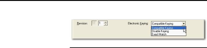
28 Configurable Flowmeter Module Features and Operational Modes
Figure 3 - General Tab
|
Changing electronic keying selections online may cause the |
|
IMPORTANT |
||
I/O communication connection to the module to be |
||
|
||
|
||
|
disrupted and may result in a loss of data. |
|
|
|
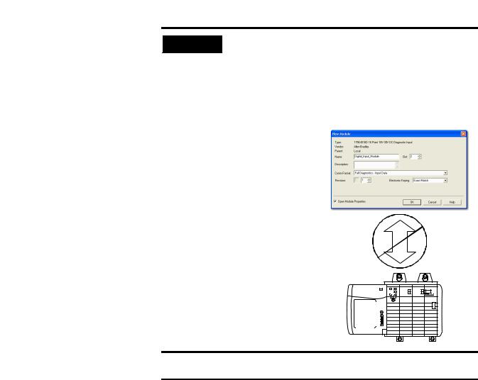
Exact Match
Exact Match keying requires all keying attributes, that is, Vendor, Product Type, Product Code (catalog number), Major Revision, and Minor Revision, of the physical module and the module created in the software to match precisely to establish communication. If any attribute does not match precisely, I/O communication is not permitted with the module or with modules connected through it, as in the case of a communication module.
Use Exact Match keying when you need the system to verify that the module revisions in use are exactly as specified in the project, such as for use in highly-regulated industries. Exact Match keying is also necessary to enable Automatic Firmware Update for the module via the Firmware Supervisor feature from a Logix5000 controller.
Rockwell Automation Publication 1756-UM010B-EN-P - December 2011
Configurable Flowmeter Module Features and Operational Modes |
29 |
|
|
EXAMPLE |
In this scenario, Exact Match keying prevents I/O |
|
communication. |
||
|
||
|
The module configuration is for a 1756-IB16D module with |
|
|
module revision 3.1. The physical module is a 1756-IB16D |
|
|
module with module revision 3.2. In this case, |
|
|
communication is prevented because the Minor Revision of |
|
|
the module does not match precisely. |
|
|
Module Configuration |
|
|
Vendor = Allen-Bradley |
|
|
Product Type = Digital Input |
|
|
Module |
|
|
Catalog Number = 1756-IB16D |
|
|
Major Revision = 3 |
|
|
Minor Revision = 1 |
|
|
Communication is prevented. |
|
|
Physical Module |
|
|
Vendor = Allen-Bradley |
|
|
Product Type = Digital Input |
|
|
Module |
|
|
Catalog Number = 1756-IB16D |
|
|
Major Revision = 3 |
|
|
Minor Revision = 2 |
|
Changing electronic keying selections online may cause the |
|
IMPORTAN |
||
I/O Communication connection to the module to be |
||
|
||
|
||
|
disrupted and may result in a loss of data. |
|
|
||
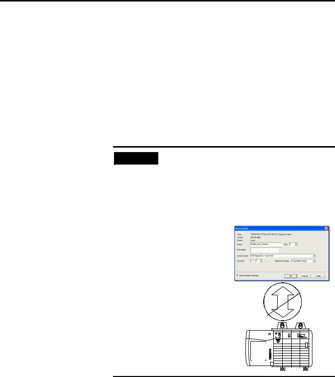
Compatible Keying |
||
Compatible Keying indicates that the module determines whether to accept or reject communication. Different module families, communication adapters, and module types implement the compatibility check differently based on the family capabilities and on prior knowledge of compatible products. Release notes for individual modules indicate the specific compatibility details.
Compatible Keying is the default setting. Compatible Keying allows the physical module to accept the key of the module configured in the software, provided that the configured module is one the physical module is capable of emulating. The exact level of emulation required is product and revision specific.
Rockwell Automation Publication 1756-UM010B-EN-P - December 2011
30 Configurable Flowmeter Module Features and Operational Modes
With Compatible Keying, you can replace a module of a certain Major Revision with one of the same catalog number and the same or later, that is higher, Major Revision. In some cases, the selection makes it possible to use a replacement that is a different catalog number than the original. For example, you can replace a 1756-CNBR module with a 1756-CN2R module.
When a module is created, the module developers consider the module’s development history to implement capabilities that emulate those of the previous module. However, the developers cannot know future developments. Because of this, when a system is configured, we recommend that you configure your module using the earliest, that is, lowest, revision of the physical module that you believe will be used in the system. By doing this, you can avoid the case of a physical module rejecting the keying request because it is an earlier revision than the one configured in the software.
EXAMPLE |
In this scenario, Compatible Keying prevents I/O |
|
communication: |
||
|
||
|
The module configuration is for a 1756-IB16D module with |
|
|
module revision 3.3. The physical module is a 1756-IB16D |
|
|
module with module revision 3.2. In this case, |
|
|
communication is prevented because the minor revision of |
|
|
the module is lower than expected and may not be |
|
|
compatible with 3.3. |
|
|
Module Configuration |
|
|
Vendor = Allen-Bradley |
|
|
Product Type = Digital Input |
|
|
Module |
|
|
Catalog Number = 1756-IB16D |
|
|
Major Revision = 3 |
|
|
Minor Revision = 3 |
|
|
Communication is prevented. |
|
|
Physical Module |
|
|
Vendor = Allen-Bradley |
|
|
Product Type = Digital Input |
|
|
Module |
|
|
Catalog Number = 1756-IB16D |
|
|
Major Revision = 3 |
Rockwell Automation Publication 1756-UM010B-EN-P - December 2011
Loading...