


 Loading...
Installation Instructions
Analog Encoder (AE) Servo Module
(Catalog Number 1756-M02AE)
The Analog Encoder (AE) Servo Module mounts in a ControlLogix™ chassis and uses a removable terminal block (RTB) to connect all field-side wiring.
Before you install your module you should have:
•installed and grounded a 1756 chassis and power supply.
•ordered and received an RTB and its components for your application.
|
page: |
|
|
Preventing Electrostatic Discharge |
2 |
|
|
Removing and Inserting Under Power (RIUP) |
3 |
|
|
Understanding Compliance to the European Union Directive |
3 |
|
|
Determining the Power Requirements |
4 |
|
|
Identifying Module Components |
4 |
|
|
Installing the Module |
6 |
|
|
Keying the Removable Terminal Block |
8 |
|
|
Wiring a Removable Terminal Block |
10 |
|
|
Wiring Examples |
13 |
|
|
Assembling the Removable Terminal Block and Housing |
22 |
|
|
Installing the Removable Terminal Block onto the Module |
23 |
|
|
Checking the LED Indicators |
24 |
|
|
Removing the Removable Terminal Block from the Module |
29 |
|
|
Removing the Module from the Chassis |
31 |
|
|
Module Specifications |
32 |
|
|
Installation Environment |
34 |
|
|
Publication 1756-IN047D-EN-P - March 2001
2 Analog Encoder (AE) Servo Module
Preventing Electrostatic Discharge
Electrostatic discharge can damage the servo board if
WARNING
you touch the circuitry or connector pins without taking precautions. Follow these guidelines when you handle
!the servo board:
•Touch a grounded object to discharge potential static.
•Wear an approved grounding wrist strap.
•Do not touch the connector or connector pins on the servo board.
•Do not touch circuit components inside the servo board.
•If available, use a static-safe work station.
Publication 1756-IN047D-EN-P - March 2001
Analog Encoder (AE) Servo Module 3
Removing and Inserting Under Power (RIUP)
This module is designed so you can remove and insert it
WARNING
under backplane power and field-side power. When you remove or insert a module while field-side power is
!applied, you can cause an electrical arc. An electrical arc can cause personal injury or property damage because it
can:
•Send an erroneous signal to your system field devices causing unintended machine motion or loss of process control.
•Cause an explosion in a hazardous environment.
Repeated electrical arcing causes excessive wear to contacts on both the module and its mating connector. Worn contacts can create electrical resistance. For additional information on RIUP, please contact your local Allen-Bradley sales representative.
Understanding Compliance to the European Union Directive
If this product bears the CE marking, it is approved for installation within the European Union and EEA regions. It has been designed and tested to meet the following directives.
EMC Directive
This product is tested to meet Council Directive 89/336/EEC Electromagnetic Compatibility (EMC) and the following standards, in whole or in part, documented in a technical construction file:
•EN 50081-2EMC - Generic Emission Standard, Part 2 - Industrial Environment
•EN 50082-2EMC - Generic Immunity Standard, Part 2 - Industrial Environment
This product is intended for use in an industrial environment.
Publication 1756-IN047D-EN-P - March 2001

4 Analog Encoder (AE) Servo Module
Low Voltage Directive
This product is tested to meet Council Directive 73/23/EEC Low Voltage, by applying the safety requirements of EN 61131-2 Programmable Controllers, Part 2 - Equipment Requirements and Test.
For specific information required by EN 61131-2, see the appropriate sections in this publication, as well as the following Allen-Bradley publications:
•Industrial Automation Wiring and Grounding Guidelines publication 1770-4.1
•Automation Systems Catalog, publication B111
This equipment is classified as open equipment and must be installed (mounted) in an enclosure during operation as a means of providing safety protection.
Determining the Power Requirements
This module receives power from the 1756 chassis power supply and requires two sources of power: 700mA at 5V and 2.5 mA at 24V from the backplane. Add this current to the requirements of all other modules in this chassis to prevent overloading the backplane power supply.
Identifying Module Components
You received two components with your order:
•1756-M02AE module
•RTB door label
Publication 1756-IN047D-EN-P - March 2001
Analog Encoder (AE) Servo Module 5
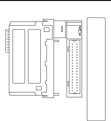
Figure 1 1756-M02AE Module
1756-M02AE module
Side view
2 Axis Servo |
Front view
RTB door label
2 |
|
|
1 |
+OUT-0 |
+OUT-1 |
||
4 |
|
|
3 |
-OUT-0 |
-OUT-1 |
||
6 |
|
|
5 |
+ENABLE-0 |
+ENABLE-1 |
||
8 |
|
|
7 |
-ENABLE-0 |
-ENABLE-1 |
||
10 |
|
|
9 |
DRVFLT-0 |
DRVFLT-1 |
||
12 |
|
|
11 |
CHASSIS |
CHASSIS |
||
14 |
|
|
13 |
IN_COM |
IN_COM |
||
16 |
|
|
15 |
HOME-0 |
HOME-1 |
||
18 |
|
|
17 |
REG24V-0 |
REG24V-1 |
||
20 |
|
|
19 |
REG5V-0 |
REG5V-1 |
||
22 |
|
|
21 |
+OK |
-OK |
||
24 |
|
|
23 |
CHASSIS |
CHASSIS |
||
26 |
|
|
25 |
+CHA-0 |
+CHA-1 |
||
28 |
|
|
27 |
-CHA-0 |
-CHA-1 |
||
30 |
|
|
29 |
+CHB-0 |
+CHB-1 |
||
32 |
|
|
31 |
-CHB-0 |
-CHB-1 |
||
34 |
|
|
33 |
+CHZ-0 |
+CHZ-1 |
||
36 |
|
|
35 |
-CHZ-0 |
-CHZ-1 |
||
1756-MO2AE
2 AXIS
ENCODER/ANALOG
SERVO
If you did not receive these components, contact your local Allen-Bradley representative.
Removable Terminal Block and Housing
A separately-ordered RTB connects field-side wiring to the module. You cannot use your module without an RTB and its components.
Use one of the following RTBs with your module:
Publication 1756-IN047D-EN-P - March 2001

6Analog Encoder (AE) Servo Module
•1756-TBCH 36-position cage clamp RTB
•1756-TBS6H 36-position spring clamp RTB
You received the following components with your RTB:
•1756-TBH standard-depth RTB housing
•wedge-shaped keying tabs and U-shaped keying bands
•RTB door label
Installing the Module
When you remove or insert an RTB with field-side
WARNING
power applied, unintended machine motion or loss of process control can occur. Exercise extreme caution
!when power is applied. Failure to observe this caution can cause personal injury.
To install the AE module:
1.Align the module circuit board with the top and bottom chassis guides.
Publication 1756-IN047D-EN-P - March 2001

Analog Encoder (AE) Servo Module 7
Figure 2 Circuit Board Alignment
 POWER
POWER
Printed circuit board
2.Push evenly and firmly to seat the module in the chassis. It is seated when the top and bottom locking tabs have snapped into place.
Publication 1756-IN047D-EN-P - March 2001
8 Analog Encoder (AE) Servo Module
Figure 3 Module Locking Tabs
Locking
tab
 POWER
POWER
Note: The 1756 chassis provides grounding for your module.
Keying the Removable Terminal Block
To identify the RTB that belongs with each module, you can use a module keying pattern. First, you can create a unique keying pattern for your module using the U-shaped keying bands that you received with your RTB. Then you can use the keying tabs to key the RTB with the same pattern as the module.
To prevent confusion, use a unique keying pattern to each module.
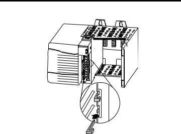
To key the module:
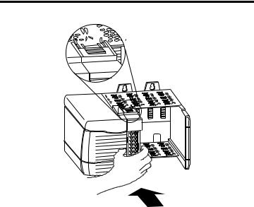
1.Insert the U-shaped keying band with the longer side near the terminals.
Publication 1756-IN047D-EN-P - March 2001
Analog Encoder (AE) Servo Module 9
Figure 4 Keying Band
 POWER
POWER
U-shaped keying band
2. Push the keying band onto the module until it snaps into place.
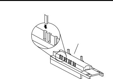
To key your removable terminal block:
1.With the rounded edge first, insert the wedge-shaped keying tab on the RTB.
Note: Insert the wedge-shaped keying tabs in positions that correspond to unkeyed positions on the module
Publication 1756-IN047D-EN-P - March 2001
10 Analog Encoder (AE) Servo Module
Figure 5 Keying Tab.
Wedge-shaped 

keying tab
Bottom of RTB
2. Push the keying tab onto the RTB until it stops.
Note: To use the RTB in future module applications, you can reposition the keying tabs on the RTB.
Wiring a Removable Terminal Block
There are two types of RTBs:
•spring clamp
•cage clamp
This section describes how to wire each type of RTB and shows wiring examples for the AE module.
Wire the RTB before installing it onto the module. Use a 1/8 inch (3.2mm) maximum flat-bladed screwdriver.
Publication 1756-IN047D-EN-P - March 2001
Analog Encoder (AE) Servo Module 11
Wiring a Spring Clamp RTB
To wire a spring clamp RTB:
1.Strip a maximum of 7/16 inch (11mm) of insulation from the end of your wire.
2.Insert the screwdriver into the outer hole of the RTB.
3.Insert the wire into the open terminal and remove the screwdriver.
Figure 6 Strain Relief Area
Strain Relief Area
4.After you complete field-side wiring, secure the wires in the strain relief area with a cable-tie.
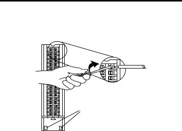
Wiring a Cage Clamp RTB
To wire a cage clamp RTB:
1.Strip 5/16 - 3/8 inch (8 - 9.5mm) of insulation from the end of your wire.
2.Insert the screwdriver into the open terminal.
Publication 1756-IN047D-EN-P - March 2001
12Analog Encoder (AE) Servo Module
3.Turn the screw clockwise to close the terminal on the wire. Use 5 lb-in. (0.5 Nm) maximum torque
Figure 7 Closing Wire Terminal.
Strain Relief Area
4.After you complete field-side wiring, secure the wires in the strain relief area with a cable-tie.
Publication 1756-IN047D-EN-P - March 2001
Loading...