


 Loading...
1302 AC Drive |
User |
(575V AC) |
|
|
Manual |
Version 3.1 |
|

Important User Information
Solid state equipment has operational characteristics differing from those of electromechanical equipment. ªSafety Guidelines for the Application, Installation and Maintenance of Solid State Controlsº (Publication SGI-1.1) describes some important differences between solid state equipment and hard±wired electromechanical devices. Because of this difference, and also because of the wide variety of uses for solid state equipment, all persons responsible for applying this equipment must satisfy themselves that each intended application of this equipment is acceptable.
In no event will the Allen-Bradley Company be responsible or liable for indirect or consequential damages resulting from the use or application of this equipment.
The examples and diagrams in this manual are included solely for illustrative purposes. Because of the many variables and requirements associated with any particular installation, the Allen-Bradley Company cannot assume responsibility or liability for actual use based on the examples and diagrams.
No patent liability is assumed by Allen-Bradley Company with respect to use of information, circuits, equipment, or software described in this manual.
Reproduction of the contents of this manual, in whole or in part, without written permission of the Allen-Bradley Company is prohibited.
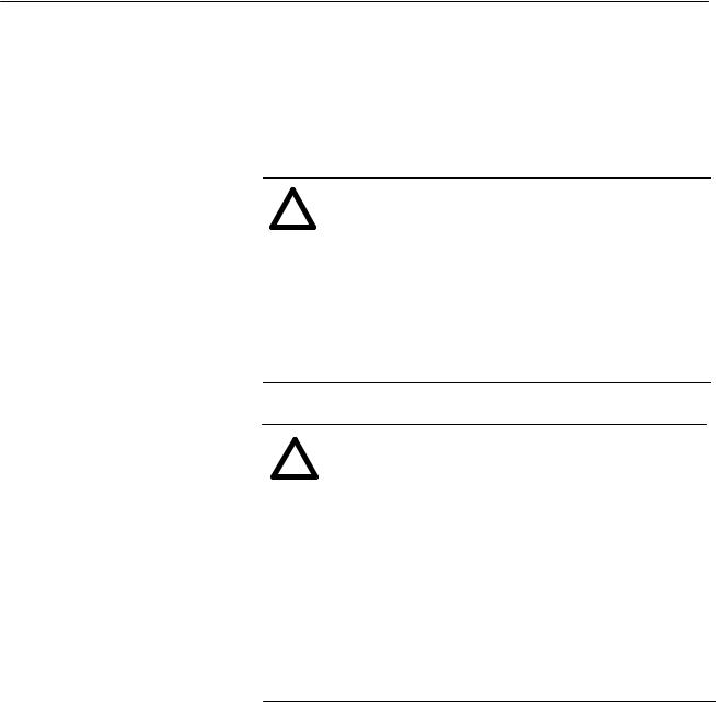
Throughout this manual we use notes to make you aware of safety considerations.
ATTENTION: Identifies information about practices
!or circumstances that can lead to personal injury or death, property damage, or economic loss.
Attentions help you:
•identify a hazard
•avoid the hazard
•recognize the consequences
Important: Identifies information that is especially important for successful application and understanding of the product.
SCANport is a trademark of Allen-Bradley Company, Inc.
PLC is a registered trademark of Allen-Bradley Company, Inc.
COLOR-KEYED is a registered trademark of Thomas & Betts Corporation
Taptite is a registered trademark of Research Engineering and Manufacturing, Inc.

Table of Contents
Introduction
Drive Description
Preinstallation
Installation
Drive Wiring
Chapter 1
Manual Objectives . . . . . . . . . . . . . . . . . . . . . . . . . . . . . . . . . . . . |
1-1 |
Chapter 2
Introduction . . . . . . . . . . . . . . . . . . . . . . . . . . . . . . . . . . . . . . . . . |
2-1 |
Standard Features . . . . . . . . . . . . . . . . . . . . . . . . . . . . . . . . . . . . |
2-1 |
Drive Description . . . . . . . . . . . . . . . . . . . . . . . . . . . . . . . . . . . . . |
2-2 |
System Diagram . . . . . . . . . . . . . . . . . . . . . . . . . . . . . . . . . . . . . |
2-3 |
Model Numbers . . . . . . . . . . . . . . . . . . . . . . . . . . . . . . . . . . . . . . |
2-6 |
Enclosure Ratings . . . . . . . . . . . . . . . . . . . . . . . . . . . . . . . . . . . . |
2-7 |
Component Locations . . . . . . . . . . . . . . . . . . . . . . . . . . . . . . . . . |
2-7 |
Option Kits . . . . . . . . . . . . . . . . . . . . . . . . . . . . . . . . . . . . . . . . . |
2-7 |
Chapter 3
General . . . . . . . . . . . . . . . . . . . . . . . . . . . . . . . . . . . . . . . . . . . |
3-1 |
Site Requirements . . . . . . . . . . . . . . . . . . . . . . . . . . . . . . . . . . . . |
3-2 |
Cooling Airflow . . . . . . . . . . . . . . . . . . . . . . . . . . . . . . . . . . . . . . |
3-4 |
Wiring Requirements . . . . . . . . . . . . . . . . . . . . . . . . . . . . . . . . . . |
3-4 |
Input Fusing . . . . . . . . . . . . . . . . . . . . . . . . . . . . . . . . . . . . . . . . |
3-7 |
Emergency Stop Installation . . . . . . . . . . . . . . . . . . . . . . . . . . . . . |
3-8 |
Motor Considerations . . . . . . . . . . . . . . . . . . . . . . . . . . . . . . . . . . |
3-9 |
Chapter 4
Introduction . . . . . . . . . . . . . . . . . . . . . . . . . . . . . . . . . . . . . . . . . |
4-1 |
Mounting the Drive . . . . . . . . . . . . . . . . . . . . . . . . . . . . . . . . . . . . |
4-1 |
Routing Wires . . . . . . . . . . . . . . . . . . . . . . . . . . . . . . . . . . . . . . . |
4-1 |
External Component Installation . . . . . . . . . . . . . . . . . . . . . . . . . . |
4-4 |
Setting the Analog Input Jumper on the Regulator Board . . . . . . . . . |
4-6 |
Motor Preparation . . . . . . . . . . . . . . . . . . . . . . . . . . . . . . . . . . . . |
4-5 |
Chapter 5
Introduction . . . . . . . . . . . . . . . . . . . . . . . . . . . . . . . . . . . . . . . . . |
5-1 |
Signal and Control Wiring . . . . . . . . . . . . . . . . . . . . . . . . . . . . . . . |
5-3 |
Digital Input Wiring . . . . . . . . . . . . . . . . . . . . . . . . . . . . . . . . . . . . |
5-4 |
Output Power Wiring . . . . . . . . . . . . . . . . . . . . . . . . . . . . . . . . . . |
5-10 |
Grounding . . . . . . . . . . . . . . . . . . . . . . . . . . . . . . . . . . . . . . . . . . |
5-10 |
Publication 1302-5.0 Ð January, 1998
ii |
Table of Contents |
Final Installation Checks
Display and Keypad
Operation
Programming
Troubleshooting
Technical Specifications
User Settings Record
Alphabetical Parameter
Listing
Replacement Parts
Chapter 6
Introduction . . . . . . . . . . . . . . . . . . . . . . . . . . . . . . . . . . . . . . . . . |
6-1 |
Power Off Checks . . . . . . . . . . . . . . . . . . . . . . . . . . . . . . . . . . . . |
6-1 |
Operational Checks . . . . . . . . . . . . . . . . . . . . . . . . . . . . . . . . . . . |
6-3 |
Chapter 7
Introduction . . . . . . . . . . . . . . . . . . . . . . . . . . . . . . . . . . . . . . . . . |
7-1 |
Display Description . . . . . . . . . . . . . . . . . . . . . . . . . . . . . . . . . . . |
7-1 |
Key Description . . . . . . . . . . . . . . . . . . . . . . . . . . . . . . . . . . . . . . |
7-2 |
LED Descriptions . . . . . . . . . . . . . . . . . . . . . . . . . . . . . . . . . . . . . |
7-3 |
Program Mode . . . . . . . . . . . . . . . . . . . . . . . . . . . . . . . . . . . . . . |
7-4 |
Monitor Mode . . . . . . . . . . . . . . . . . . . . . . . . . . . . . . . . . . . . . . . |
7-6 |
Drive Control . . . . . . . . . . . . . . . . . . . . . . . . . . . . . . . . . . . . . . . . |
7-8 |
Chapter 8
Introduction . . . . . . . . . . . . . . . . . . . . . . . . . . . . . . . . . . . . . . . . . |
8-1 |
Program Security . . . . . . . . . . . . . . . . . . . . . . . . . . . . . . . . . . . . . |
8-2 |
Parameter Descriptions . . . . . . . . . . . . . . . . . . . . . . . . . . . . . . . . |
8-4 |
Chapter 9
Introduction . . . . . . . . . . . . . . . . . . . . . . . . . . . . . . . . . . . . . . . . . |
9-1 |
Verifying DC Bus Voltage . . . . . . . . . . . . . . . . . . . . . . . . . . . . . . . |
9-1 |
Troubleshooting the Drive Using Fault Codes . . . . . . . . . . . . . . . . . |
9-2 |
Accessing and Clearing the Error Log . . . . . . . . . . . . . . . . . . . . . . |
9-5 |
Power Module Check . . . . . . . . . . . . . . . . . . . . . . . . . . . . . . . . . . |
9-7 |
Appendix A
Service Conditions . . . . . . . . . . . . . . . . . . . . . . . . . . . . . . . . . . . . |
A-1 |
Dimensions . . . . . . . . . . . . . . . . . . . . . . . . . . . . . . . . . . . . . . . . . |
A-1 |
Environmental Conditions . . . . . . . . . . . . . . . . . . . . . . . . . . . . . . . |
A-1 |
Drive Inputs . . . . . . . . . . . . . . . . . . . . . . . . . . . . . . . . . . . . . . . . . |
A-2 |
Drive Outputs . . . . . . . . . . . . . . . . . . . . . . . . . . . . . . . . . . . . . . . |
A-2 |
Appendix B
Parameter Table . . . . . . . . . . . . . . . . . . . . . . . . . . . . . . . . . . . . . B±1
Appendix C
Parameter List . . . . . . . . . . . . . . . . . . . . . . . . . . . . . . . . . . . . . . . C±1
Appendix D
Parts Table . . . . . . . . . . . . . . . . . . . . . . . . . . . . . . . . . . . . . . . . . D±1
Publication 1302-5.0 Ð January, 1998
1±1 |
Chapter 1 |
Introduction
Manual Objectives
The purpose of this manual is to provide you with the necessary information to install, program, start up and maintain the 1302 AC Drive. This manual should be read in its entirety before operating, servicing or initializing the 1302 Drive.
This manual is intended for qualified electrical personnel responsible for installing, programming, starting up, and maintaining the 1302 drive.
This manual describes how to install and troubleshoot the 1302 AC drive. Drive installation consists of the following basic tasks:
•Plan your installation using the guidelines presented in chapter 3. If your installation must be in compliance with Electromagnetic Compatibility Standards, read Appendix E also.
•Mount the Drive and install external components according to the guidelines presented in chapter 4.
•Wire the Drive's input power, output power, and control signal terminal strip using the instructions in chapter 5.
•Adjust parameter values, if required. The parameters are described in chapter 8. For quick reference, the factory-set values are listed in Appendix B.
•Perform the power-off and power-on checks described in chapter 6 to complete the installation.
If problems occur during Drive operation, refer to chapter 9. Appendix F lists the parts of the Drive that can be replaced. Before you begin the installation procedure, become familiar with the Drive by reading chapter 2, which provides an overview of the Drive and its features, chapter 7, which describes the operation of the keypad and the display, and Appendix A, which lists the Drive's technical specifications.
Publication 1302-5.0 Ð January, 1998

1±2 Introduction
ATTENTION: Only qualified electrical personnel
!familiar with the construction and operation of this equipment and the hazards involved should install, adjust, operate and/or service this equipment. Read and understand this section in its entirety before proceeding. Failure to observe this precaution could result in bodily injury or loss of life.
ATTENTION: An incorrectly installed or applied Drive can result in component damage or a reduction in product life. Wiring or application errors such as undersizing the motor, incorrect or inadequate AC supply or excessive ambient temperatures may result in damage to the Drive or motor.
ATTENTION: This Drive contains ESD (Electrostatic Discharge) sensitive parts and assemblies. Static control precautions are required when installing, testing, servicing or repairing this assembly. Component damage may result if ESD control procedures are not followed. If you are not familiar with static control procedures, reference Allen±Bradley Publication 8000 ± 4.5.2, Guarding against Electrostatic Damage or any other applicable ESD protection handbook.
Publication 1302-5.0 Ð January, 1998
2±1 |
Chapter 2 |
1302 AC Drive Description
Introduction
Standard Features
This chapter describes the 1302 Drive and how to identify it based on its model number. This chapter also provides power and enclosure rating information.
The 1302 Drive has the following features:
•On-board keypad and display providing: Start/Stop/Reset control
Forward/Reverse (reverse-disable selectable)
Setpoint adjustment, Motor RPM, %load, or output voltage display
Drive diagnostics
•500 millisecond power dip ride-through
•150% overload for one minute
•0.5 to 240 Hz three-phase voltage output
•NEMA 1 and NEMA 4/12 enclosures
•A snubber resistor braking signal and a scaled voltage analog output (0 to 10 VDC) which is proportional to:
Output frequency Output amps Output voltage Selected reference
•Quiet motor operation with high carrier frequency selection
•Drive protection: Overcurrent Short circuit Ground fault Overvoltage Undervoltage Overtemperature
•UL/CSA electronic overload that meets NEC/CEC requirements
•User-selectable relay contact for indications of Drive running, Drive faulted, or Drive at selected speed
•User-selectable power-up start, auto-restart, and coast-to-rest or ramp-to-rest stop functions
•User-selectable local or remote operation
•29 user±adjustable software parameters
Publication 1302-5.0 Ð January, 1998
2±2 |
1302 AC Drive Description |
Drive Description
The 1302 Drive is an AC PWM (pulse±width±modulated) inverter that operates on single±or three±phase power as detailed in Figures 2.1 and 2.2. AC input power is applied to the Drive's input terminals. Voltage transients are suppressed by three metal-oxide-varistor (MOV) suppressors. These suppressors keep any input voltage transients within the maximum voltage rating of the input diode module.
The input diode module rectifies the incoming AC voltage into a constant DC bus voltage which is filtered by the DC bus capacitor bank. An internal DC-to-DC power supply uses power from the DC bus and provides the necessary voltages required by the Drive. Under regulator software control, the IGBT (insulated-gate bipolar-transistor) inverter bridge converts the constant DC voltage into an AC PWM waveform. The regulator switches the IGBT inverter bridge using a 4, 6, or 8 kHz carrier frequency (user-selectable). A low carrier frequency maximizes the power rating of the Drive but also increases acoustic noise. A high carrier frequency selection reduces acoustic noise but results in a derating of the Drive's efficiency.
The volts per hertz (V/Hz) regulator governs the open-loop operation of the Drive for adjustable speed performance of AC induction and synchronous motors. The regulator maintains a ratio of voltage to output frequency that provides constant or variable torque across a wide speed range. Drive operation can be adjusted by the parameters entered through the keypad. A microprocessor on the Regulator board controls Drive regulation. See Figure 2.3. The Regulator board accepts internal power feedback signals and an external speed reference signal. The Regulator board provides display data for a four-character display, which is used to indicate Drive parameters, parameter values, and fault codes.
The Drive can be controlled either locally through the keyboard and display (see Chapter 7) or remotely through the terminal strip (see Chapter 5).
The Drive is intended to operate trip-free under any condition. The Drive uses selected signals to extend the acceleration (starting) and deceleration (stopping) rates of the motor when an overcurrent condition occurs. When a fault does occur, however, the regulator generates an instantaneous electronic trip (IET) signal to turn the Drive off (coast-to-rest). The Drive stores an indication or record of the IET fault, which can be viewed on the four-character display. After a fault, the STOP/RESET key or a user-supplied IET RESET pushbutton must be pressed to reset the IET signal and clear the fault from the Drive.
Publication 1302-5.0 Ð January, 1998

1302 AC Drive Description 2±3
Figure 2.1
1302 System Diagram
|
|
|
DIODE |
IGBT |
|
|
|
MODULE |
MODULE |
|
|
|
|
|
DC |
CT |
|
LINE INPUT |
|
|
|
|
|
575VAC |
|
|
|
|
|
|
R |
|
|
|
AC |
|
|
|
|
|
|
|
S |
|
|
Induction |
|
|
T |
|
|
U |
Motor |
|
|
+ |
V |
|
|
|
|
|
|
||
|
|
|
|
|
|
|
|
|
|
W |
|
TO OPTIONAL + |
|
|
|
|
|
SNUBBER |
± |
|
|
|
|
RESISTOR |
|
|
|
|
|
|
+ |
10 VDC |
|
|
|
|
10 VDC COMMON |
|
|
|
|
|
± |
|
|
|
|
|
|
|
|
|
|
|
|
24 VDC |
|
|
|
|
|
24 VDC COMMON |
|
|
|
|
|
+15 VDC |
|
POWER |
|
|
|
±15 VDC |
|
|
|
|
|
BUS VOLT |
|
SUPPLY |
|
TO |
J4 |
FEEDBACK |
BUS CURRENT FEEDBACK |
|
|
FIG |
|
|
+5 VDC |
|
|
2.2 |
|
|
REGULATOR COMMON |
|
|
|
|
|
GATE SIGNALS |
|
|
Publication 1302-5.0 Ð January, 1998

2±4 |
1302 AC Drive Description |
|
Figure 2.2 |
|
1302 System Diagram Cont. |
F E |
E E |
E E K
E |
E |
Publication 1302-5.0 Ð January, 1998
1302 AC Drive Description 2±5
Figure 2.3
Regulator Board Component Locations
% % % % %6%7% % %$ $ $ $ $ $6
! "
6
! #
7&
6& C
Publication 1302-5.0 Ð January, 1998
2±6 |
1302 AC Drive Description |
Model Numbers
A model number identifies each 1302 AC Drive as detailed in Table 2.A. This number appears on the shipping label and on the Drive's nameplate located on the right side of the Drive housing. The Drive's model number contains codes that indicate: input voltage range, enclosure rating, and horsepower rating. Drive enclosure ratings are detailed later in this chapter. All 1302 Drives described in this instruction manual function in the same manner.
Table 2.A - Power and NEMA Enclosure Ratings
|
|
|
|
|
|
|
|
Power |
|
Input Voltage |
|
Enclosure |
|
Input |
Input |
Output |
Loss |
del e |
Horsepower |
Size |
|
Amps |
KVA |
Amps* |
Watts** |
|
|
|
|
|
|
|
|
|
|
1302±C001±AA |
575 VAC |
1 |
B |
1 |
2.0 |
2.0 |
1.6 |
50 |
|
|
|
|
|
|
|
|
|
1302±C001±AF |
575 VAC |
1 |
B |
4X/12 |
2.0 |
2.0 |
1.6 |
50 |
|
|
|
|
|
|
|
|
|
1302±C002±AA |
575 VAC |
2 |
B |
1 |
3.4 |
3.3 |
2.7 |
90 |
|
|
|
|
|
|
|
|
|
1302±C002±AF |
575 VAC |
2 |
B |
4X/12 |
3.4 |
3.3 |
2.7 |
90 |
|
|
|
|
|
|
|
|
|
1302±C003±AA |
575 VAC |
3 |
B |
1 |
5.2 |
5.1 |
4.3 |
120 |
|
|
|
|
|
|
|
|
|
1302±C003±AF |
575 VAC |
3 |
B |
4X/12 |
5.2 |
5.1 |
4.3 |
120 |
|
|
|
|
|
|
|
|
|
1302±C005±AA |
575 VAC |
5 |
B |
1 |
7.5 |
7.5 |
6.2 |
150 |
|
|
|
|
|
|
|
|
|
1302±C005±AF |
575 VAC |
5 |
B |
4X/12 |
7.5 |
7.5 |
6.2 |
150 |
|
|
|
|
|
|
|
|
|
1302±C007±AA |
575 VAC |
7.5 |
C |
1 |
10.9 |
10.9 |
9.0 |
180 |
|
|
|
|
|
|
|
|
|
1302±C007±AF |
575 VAC |
7.5 |
C |
4X/12 |
10.9 |
10.9 |
9.0 |
180 |
|
|
|
|
|
|
|
|
|
1302±C010±AA |
575 VAC |
10 |
C |
1 |
14.5 |
14.4 |
12.0 |
250 |
|
|
|
|
|
|
|
|
|
1302±C010±AF |
575 VAC |
10 |
C |
4X/12 |
14.5 |
14.4 |
12.0 |
250 |
*To properly size the drive for motor nameplate horsepower and amps, refer to Chapter 3 for more information.
**Full load at all carrier frequencies. Refer to Chapter 3 for more information.
Publication 1302-5.0 Ð January, 1998

1302 AC Drive Description 2±7
Enclosure Ratings |
Each 1302 Drive has one of the following ratings: |
|
Table 2.B - 1302 NEMA Ratings |
||
|
|
|
|
NEM |
|
|
Rating |
Description |
1 |
Vented. For general3purpose indoor applications. |
|
|
|
|
|
4X/12 |
Not vented. Supplied with base and keypad gaskets. For use in indoor |
|
|
environments that require a water3tight and dust3tight enclosure. An |
|
|
enclosure with this NEMA rating encompasses both ratings (4X and 12). |
|
|
|
12 |
Intended for use in indoor environments that require a dust3tight and |
|
|
|
drip3tight enclosure. |
For clarity in this manual, 1302 Drive enclosures are identified by size as enclosures B or C. Refer to Chapter 3 for the dimensions of enclosures B through C.
Component Locations |
Figures 2.4 and 2.5 show the main components of the 1302 Drives |
|
(enclosures B and C). Appendix F lists replacement parts. |
Option Kits |
The option kit which is available for the 1302 Drive is detailed in |
|
Table 2.C. |
Table 2.C - 1302 Option Kits
|
Option Kit |
Instruction |
Option Kit Description |
Model Number |
Manual |
|
|
|
Low Energy Snubber Resistor Braking Kit for |
1302-2DB5010 |
1302-5.1 |
1302 Drives* |
|
|
** Snubber resistor braking kits require connection to the snubber resistor braking 10V power supply. See Chapter 5 (Snubber resistor wiring) for more information.
Publication 1302-5.0 Ð January, 1998

2±8 |
1302 AC Drive Description |
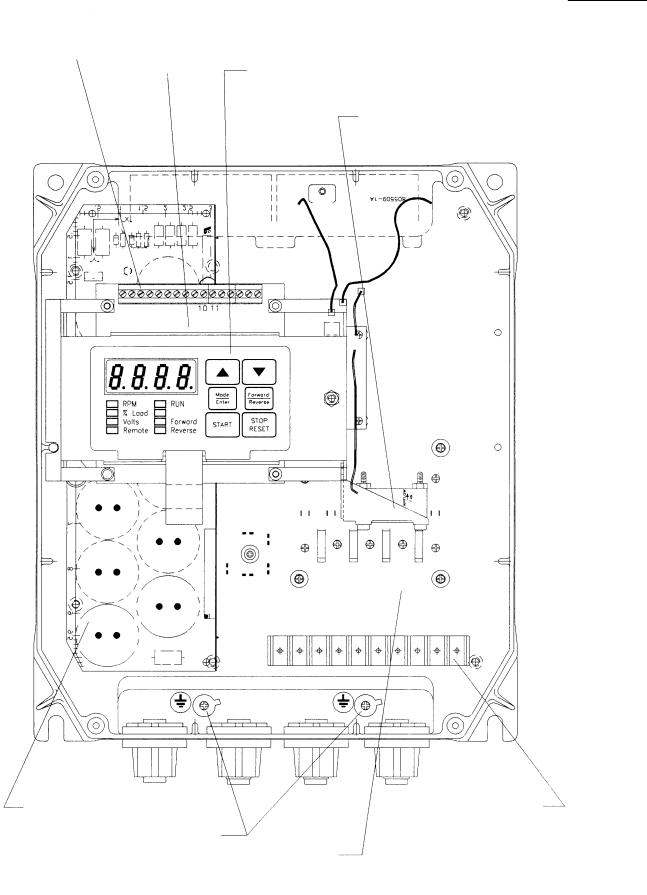
Figure 2.4
Enclosure B Component Locations
REGULATOR PCB
CONTROL TERMINAL |
MEMBRANE SWITCH/ |
|
STRIP |
||
BRACKET ASSEMBLY |
||
|
||
|
INTERNAL FAN |
|
|
ASSEMBLY |
POWER PCB
CAPACITOR PCB
(3&5 HP ONLY)
GND CONNECTION
POWER TERMINAL
STRIP
Publication 1302-5.0 Ð January, 1998
1302 AC Drive Description 2±9
Figure 2.5
Enclosure C Component Locations
CONTROL TERMINAL
STRIP REGULATOR PCB MEMBRANE SWITCH/ BRACKET ASSEMBLY
INTERNAL FAN
ASSEMBLY
CAPACITOR PCB |
POWER TERMINAL |
GND CONNECTIONS |
STRIP |
|
|
|
POWER PCB |
Publication 1302-5.0 Ð January, 1998
2±10 |
1302 AC Drive Description |
This Page Intentionally Blank
Publication 1302-5.0 Ð January, 1998

1302 AC Drive Description 2±11
Publication 1302-5.0 Ð January, 1998

2±12 |
1302 AC Drive Description |
Table 2.A
1302 Model Number Notation
Model Number |
Input Voltage |
Horsepower |
|
1.5 |
6.2 Nm (55 lb-in) |
Ð |
|
2 |
6.2 Nm (55 lb-in) |
Ð |
|
3 |
6.2 Nm (55 lb-in) |
6.2 Nm (55 lb-in) |
|
5 |
6.2 Nm (55 lb-in) |
6.2 Nm (55 lb-in) |
|
7.5 |
6.2 Nm (55 lb-in) |
6.2 Nm (55 lb-in) |
|
10 |
6.2 Nm (55 lb-in) |
6.2 Nm (55 lb-in) |
|
15 |
13.6 Nm (120 lb-in) |
6.2 Nm (55 lb-in) |
|
20 |
13.6 Nm (120 lb-in) |
6.2 Nm (55 lb-in) |
|
25 |
13.6 Nm (120 lb-in) |
6.2 Nm (55 lb-in) |
|
30 |
13.6 Nm (120 lb-in) |
13.6 Nm (120 lb-in) |
|
40 |
22 Nm (200 lb-in) |
13.6 Nm (120 lb-in) |
|
50 |
22 Nm (200 lb-in) |
13.6 Nm (120 lb-in) |
|
60 |
22 Nm (200 lb-in) |
13.6 Nm (120 lb-in) |
|
75 |
22 Nm (200 lb-in) |
22 Nm (200 lb-in) |
|
100 |
22 Nm (200 lb-in) |
||
|
|||
125 |
Ð |
22 Nm (200 lb-in) |
|
150 |
22 Nm (200 lb-in) |
||
Ð |
|||
|
|
||
|
|
|
|
Note: |
|
|
Figure 2.19
Motor Thermostat/Brush Wear Wiring
12
BRUSH WEAR
13
MOTOR THERMOSTAT
14
115V HI
115VAC Option Board CON 2
115VAC Thermostat/Brush Wear Circuit
Publication 1302-5.0 Ð January, 1998
3±1
General
Chapter 3
1302 Preinstallation
Chapter 3 provides information that you must use when planning a 1302 AC Drive installation. Installation site, wiring and motor application requirements are included in this chapter.
ATTENTION: The following information is merely a
!guide for proper installation. The National Electrical Code and any other governing regional or local code will overrule this information. The Allen±Bradley Company cannot assume responsibility for the compliance or noncompliance to any code, national, local or otherwise for the proper installation of this Drive or associated equipment. A hazard of personal injury and/or equipment damage exists if codes are ignored during installation.
ATTENTION: Hazard of electric shock or equipment
!damage exist if the Drive is not installed correctly. The National Electrical Code (NEC) and local codes outline
provisions for safely installing electrical equipment. Installation must comply with specifications regarding wire types, conductor sizes, branch circuit protection and disconnect devices. Only qualified electrical personnel familiar with the construction and operation of the 1302 Drive and the hazards involved should install, adjust, operate, or service this equipment. Read and understand this manual and other applicable manuals in their entirety before proceeding. Failure to do so may result in personal injury and/or equipment damage.
Publication 1302-5.0 Ð January, 1998
3±2 |
1302 Preinstallation |
Site Requirements
It is important to properly plan before installing a 1302 Drive to ensure that the Drive's environment and operating conditions are satisfactory. Note that no devices are to be mounted behind the Drive. This area must be kept clear of all control and power wiring. Read the following recommendations before continuing with the Drive installation.
Before deciding on an installation site, consider the following guidelines:
•The area chosen should allow the space required for proper airflow as specified in the next section.
•Do not install the Drive above 1000 meters (3300 feet) without derating output power. For every 91.4 meters (300 feet) above 1000 meters (3300 feet), derate the output current by 1%.
•Verify that the Drive location will meet the following
environmental conditions:
Operating temperature (ambient): 0 to +40°C (32 to 104°F) Storage temperature (ambient): ± 40 to +65°C (±40 to +149°F)
Humidity: 5 to 95% (non-condensing)
•Verify that NEMA 1 Drives can be kept clean, cool, and dry.
•Be sure NEMA 1 Drives are located away from oil, coolants, or other airborne contaminants.
•Verify that the AC power distribution system meets the service conditions specified in table
Determining Total Area Requirements
Figures 3.1 and 3.2 provide drive dimensions for enclosures B and C as an aid in calculating the total area required by the 1302 Drives. Appendix A lists drive weights.
Publication 1302-5.0 Ð January, 1998
1302 Preinstallation 3±3
Figure 3.1
Enclosure B Dimensions
Figure 3.2
Enclosure C Dimensions
Publication 1302-5.0 Ð January, 1998
3±4 |
1302 Preinstallation |
Cooling Airflow
Be sure there is adequate clearance for air ventilation around the Drive. For best air movement, do not mount 1302 Drives directly above each other. Note that no devices are to be mounted behind the Drive. This area must be kept clear of all control and power wiring. See Table 3.A for a listing of the recommended air flow clearances.
Table 3.A - Air Flow Clearances
|
nclosure |
|
|
|
|
|
B |
C |
|
|
|
Minimum distance from the sides of the drive if adjacent to non-heat producing |
102 mm |
102 mm |
equipment |
(4º) |
(4º) |
|
|
|
Minimum distance from the top and bottom of the drive if adjacent to non-heat |
102 mm |
102 mm |
producing equipment |
(4º) |
(4º) |
|
|
|
Minimum distance from the sides of the drive if adjacent to other drives |
102 mm |
102 mm |
|
(4º) |
(4º) |
|
|
|
Minimum distance from the top and bottom of the drive if adjacent to other drives |
254 mm |
254 mm |
|
(10º) |
(10º) |
Wiring Requirements
Verifying the Drive's Power Loss Ratings
When installing a 1302 Drive inside of another enclosure, you should consider the Drive's watts loss rating shown in Table 2.A. This table lists the typical full load power loss watts value under all operating carrier frequencies. Ensure adequate ventilation is provided based on the Drive's watts loss rating.
Evaluate the following areas of Drive wiring before you start the installation: size of available conduit, size of power and control wiring, and motor lead lengths.
Verifying Conduit Sizes
It is important to determine the size of the conduit openings accurately so that the wire planned for a specific entry point will fit through the opening. Figures 4.1 and 4.2 detail conduit opening sizes.
Recommended Power Wire Sizes
Size input power wiring according to applicable codes to handle the Drive's continuous-rated input current. Size output wiring according to applicable codes to handle the Drive's continuous-rated output
current. Table 3.B provides recommended power wiring sizes. Use only copper wire with a minimum temperature rating of 60/75°C.
Table 3.C contains the recommended tightening torque values for all power wiring terminals.
Publication 1302-5.0 Ð January, 1998
|
|
|
1302 Preinstallation 3±5 |
||
|
Table 3.B - Recommended Power Wire Sizes |
|
|
|
|
|
|
|
|
|
|
|
|
|
|
Size of Wire |
|
|
Type of Wiring |
Terminals |
|
(maximum)* |
|
|
AC Input Power |
R(L1), S(L2), T(L3) |
|
14 AWG, 2 (mm2) |
|
|
Output Power |
U(T1), V(T2), W(T3) |
|
14 AWG, 2 (mm2) |
|
|
DC Bus |
0 , + |
|
14 AWG, 2 (mm2) |
|
|
Snubber Resistor |
+10 VDC, 10 COM |
|
14 AWG, 2 (mm2) |
|
|
Ground |
GND |
|
14 AWG, 2 (mm2) |
|
Table 3.C - Recommended Power Terminal Tightening Torque
Drives |
Terminals |
Maximum Tightening Torque |
|
|
|
All |
All power wires |
1.08 Newton/meters (9.5 in/lb) |
Recommended Control and Signal Wire Sizes
Table 3.D shows the recommended wire sizes to connect I/O signals to the terminal strip on the Regulator board. The minimum wire insulation rating is 600V. Operator controls can be up to 303 meters (1000 feet) from the 1302 Drive. All signal wires should be twisted-pair.
Table 3.D - Recommended Control and Signal Wire Sizes and Tightening Torque
|
|
Minimum |
Maximum |
Maximum |
Drives |
Terminals |
Wire Size |
Wire Size |
Tightening Torque |
|
|
|
|
|
All |
1016 |
20 AWG, 0.5 (mm2) |
14 AWG, 2 (mm2) |
0.5 Newton/meters |
|
|
|
|
(4.5 in/lb) |
Publication 1302-5.0 Ð January, 1998
3±6 |
1302 Preinstallation |
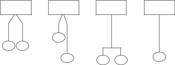
Recommended Motor Lead Lengths
The following motor lead lengths are recommended to reduce line disturbances and noise. See Figure 3.3.
•For applications using one motor, motor lead length should not exceed 76 meters (250 feet).
•For applications with multiple motors, total motor lead length should not exceed 76 meters (250 feet).
When total lead length exceeds 76 meters (250 feet), nuisance trips can occur, caused by capacitive current flow to ground. Note that these capacitively-coupled currents should be taken into consideration when working in areas where drives are running. If the motor lead length must exceed these limits, the addition of output line reactors or other steps must be taken to correct the problem. See Table 3.E. Note that the motor lead lengths shown in Table 3.E are only guidelines. Your application may be restricted to a shorter motor lead length due to:
•The type of wire
•The placement of the wire (for example, in conduit or a cable tray)
•The type of line reactor (For example, with or without LC filters)
•The type of motor
Figure 3.3
How to Measure Motor Lead Lengths
1302 Drive |
1302 Drive |
1302 Drive |
38m (125') |
15m (50') |
|
|
38m (125') |
|
61m (200') |
|
|
|
|
|
|
Motor |
|
|
|
61m (200') |
|
|
Motor |
Motor |
|
|
|
|
8m (25') |
8m (25') |
|
Motor |
Motor |
Motor |
|
|
All examples represent 76m (250') of motor lead length.
1302 Drive
76m (250')
Motor
Publication 1302-5.0 Ð January, 1998

1302 Preinstallation 3±7
Table 3.E
Maximum Motor Cable Length Restrictions in meters (Feet) for 1302
|
|
No External Devices |
w/ 1204±TFA1 Terminator |
w/ Reactor/Filter at Drive |
||||||
|
|
|
|
|
|
|
|
|
|
|
|
|
Motor |
|
|
Motor |
|
|
Motor |
|
|
|
|
|
|
|
|
|
|
|
|
|
|
|
A |
B |
1329R |
A |
B |
1329R |
A |
B |
1329R |
Drive kW |
Motor kW |
Any |
Any |
Any |
Any |
|
Any |
Any |
|
|
(HP) |
(HP) |
Cable |
Cable |
Cable |
Cable |
|
Cable |
Cable |
|
|
|
|
|
|
|
|
|
|
|
|
|
0.75 (1) |
0.75 (1) |
NR |
NR |
45.7 |
NR |
121.9 |
152.4 |
152.4 |
152.4 |
152.4 |
|
|
|
|
(150) |
|
(400) |
(500) |
(500) |
(500) |
(500) |
|
|
|
|
|
|
|
|
|
|
|
1.5 (2) |
1.5 (2) |
NR |
NR |
45.7 |
NR |
121.9 |
152.4 |
152.4 |
152.4 |
152.4 |
|
|
|
|
(150) |
|
(400) |
(500) |
(500) |
(500) |
(500) |
|
|
|
|
|
|
|
|
|
|
|
2.2 (3) |
2.2 (3) |
NR |
NR |
45.7 |
NR |
152.4 |
304.8 |
152.4 |
152.4 |
304.8 |
|
|
|
|
(150) |
|
(500) |
(1000) |
(500) |
(500) |
(1000) |
|
|
|
|
|
|
|
|
|
|
|
3.7 (5) |
3.7 (5) |
NR |
NR |
45.7 |
NR |
152.4 |
304.8 |
152.4 |
152.4 |
304.8 |
|
|
|
|
(150) |
|
(500) |
(1000) |
(500) |
(500) |
(1000) |
5.6 (7.5) |
5.6 (7.5) |
NR |
NR |
76.2 |
NR |
NR |
NR |
152.4 |
152.4 |
304.8 |
|
|
|
|
(250) |
|
|
|
(500) |
(500) |
(1000) |
|
|
|
|
|
|
|
|
|
|
|
7.5 (10) |
7.5 (10) |
NR |
NR |
76.2 |
NR |
NR |
NR |
152.4 |
152.4 |
304.8 |
|
|
|
|
(250) |
|
|
|
(500) |
(500) |
(1000) |
Type A Motor Characteristics: No phase paper or misplaced phase paper, lower quality insulation systems, corona inception voltages
|
between 850 and 1000 volts |
|
Type B Motor Characteristics: |
Properly placed phase paper, medium quality insulation systems, corona inception voltages between |
|
|
1000 and 1200 volts. |
|
1329R Motors |
These AC Variable Speed motors are ªPower Matchedº for use with Allen±Bradley Drives. Each motor |
|
|
is energy efficient and designed to meet or exceed the requirements of the Federal Energy Act of 1992. |
|
|
All 1329R motors are optimized for variable speed operation and include premium inverter grade |
|
|
insulation systems which meet or exceed NEMA MG1. Part 31.40.4.2 |
|
|
1329R motors at 575V are rated 1850V insulation value. |
|
Recommended MTE Reactor and LC Filter: |
|
|
|
1 hp at 4kHz use MTE part number: |
RL± 00803C |
|
1 hp at 6/8kHz use MTE part number |
RL± 00202C |
|
2/3/5 hp use MTE part number |
RL± 00803C |
|
7.5 hp use MTE part number |
RL± 01803C |
|
10 hp use MTE part number |
RL± 01803C |
Input Fusing
!
ATTENTION: The 1302 AC Drive does not provide input power short circuit fusing. Specifications for the recommended fuse size and type to provide Drive input power protection against short circuits are provided in Table 3.F. Branch circuit breakers or disconnect switches cannot provide this level of protection for Drive components.
Input line branch circuit protection fuses must be used to protect the input power lines. See Figure 5.A. Table 3.F shows recommended fuse values. These fuse ratings are applicable for one Drive per branch circuit. No other load may be applied to that fused circuit. Note that contactors and circuit breakers are not recommended for AC input line branch protection.
Publication 1302-5.0 Ð January, 1998

3±8 |
1302 Preinstallation |
Table 3.F- AC Input Line Fuse Selection Values
Model |
|
Fuse |
Number |
|
Rating* |
1302±C001±AA |
|
4A |
1302±C001±AF |
|
4A |
|
|
|
1302±C002±AA |
|
7A |
1302±C002±AF |
|
7A |
1302±C003±AA |
|
10A |
|
|
|
1302±C003±AF |
|
10A |
1302±C004±AA |
|
15A |
1302±C005±AA |
|
15A |
|
|
|
1302±C005±AF |
|
20A |
1302±C007±AF |
|
20A |
1302±C010±AA |
|
25A |
|
|
|
1302±C010±AF |
|
25A |
* Recommended fuse type: UL Class J, 600V, time delay, or equivalent.
Emergency Stop Installation
!
ATTENTION: The 1302 Drive control circuitry includes solid state components. If hazards due to accidental contact with moving machinery or unintentional flow of liquid, gas or solids exist, an additional hardwired stop circuit is required to remove AC line power to the Drive. When AC input power is removed, there will be a loss of inherent regenerative braking effect and the motor will coast to a stop. An auxiliary braking method may be required.
Depending upon the requirements of the application, the 1302 Drive can be programmed to provide either a coast-to-rest (default) or a ramp-to-rest (user-option) operational stop without physical separation of the power source from the motor. Refer to Chapters 5 and 8 (parameter F-16) for more information on how to program an operational stop.
In addition to the operational stop, users must provide a hardwired emergency stop external to the Drive. The emergency stop circuit must contain only hardwired electromechanical components. Operation of the emergency stop must not depend on electronic logic (hardware or software) or on the communication of commands over an electronic network or link.
Complying with Machinery Safety Standard EN 6024±1:1992
This section applies to users who must comply with machinery safety standard EN 60204-1:1992, part 9.2.5.4, Emergency Stop.
The 1302 Drive coast-to-rest stop is a category 0 operational stop. The ramp-to-rest stop is a category 1 operational stop.
Publication 1302-5.0 Ð January, 1998

1302 Preinstallation 3±9
Motor Considerations
The required external hardwired emergency stop must be either a category 0 or 1 stop, depending on the user's risk assessment of the associated machinery. In order to fully comply with machinery safety standard EN 60204-1:1992, part 9.2.5.4, at least one of the two stop methods must be a category 0 stop.
To obtain motor nameplate horsepower, the Drive's output current rating at the selected carrier frequency should be equal to or greater than motor nameplate current. If the motor nameplate current rating is higher than the Drive's output current rating, derate motor horsepower by the ratio of the Drive's output ampere rating (at the selected carrier frequency) to the motor nameplate current. Note that this approximation is only accurate if the Drive and the motor have nearly the same rating.
Single Motor Applications
Size the drive and motor for the load and speed requirements of the specific application.
The motor's operating current must not exceed the drive's rated output current (at the selected carrier frequency). In addition, the motor's horsepower rating (for example, 1, 2, 3, 5, 7, 10 HP) must not be more than one horsepower range larger than the Drive's horsepower rating.
If the motor will be operated below one-half of its rated speed, the motor overload relay may not protect the motor because of reduced cooling action due to the reduced speed. A motor thermostat, internal to the motor, should be installed to monitor the actual temperature of the windings.
Multiple ± Motor Applications
One Drive can run two or more motors. Adhere to the following requirements to assure correct Drive operation in this case:
•When starting and stopping all the motors at the same time (using the Drive for starting and stopping), the sum of the full-load sine wave currents of all the motors must be equal to or less than the maximum sine wave output current at the selected carrier frequency for the Drive.
F r exa e: |
FLA |
+ |
FLA |
+ |
FLA |
= |
TLA |
|
(M t r 1) |
|
(M t r 2) |
|
(M t r 3) |
|
(T ta L ad) |
Where: TLA <100% rated dr ve ut ut at the se ected carr er freque cy
•When one or more of the motors connected to the output of the Drive are to start independently (using a secondary switching device to add or remove the motor from the circuit):
Any motor that starts or stops while the Drive is running must have a current rating less than 10% of the maximum sine wave current rating of the Drive at the selected carrier frequency.
Publication 1302-5.0 Ð January, 1998
3±10 |
1302 Preinstallation |
The sum of the maximum full-load sine wave currents of all the motors connected continuously to the Drive must be less than the maximum output current rating under all conditions.
Note that each motor requires separate thermal overload protection (for example, a motor relay or a motor thermostat).
Publication 1302-5.0 Ð January, 1998

4±1 |
Chapter 4 |
Installation
Introduction
This chapter shows how to mount the 1302 Drive and its external components. Also shown are the entry areas for routing wiring in and out of the Drive.
Mounting the Drive
Routing Wires
Attach the drive to the selected flat, vertical surface using the mounting holes provided. Enclosure B and C Drives have four mounting holes. In order to maintain a flat mounting surface and to ensure that bolt tightness is maintained, use washers under the bolt heads. Refer to Figures 3.1 and 3.2 for Drive mounting dimensions. Use the following user-supplied mounting bolts and washers:
•Enclosure B Drives: four M8 (5/16º)
•Enclosure C Drives: four M8 (5/16º)
All wiring should be installed in conformance with the applicable local, national, and international codes (e.g., NEC/CEC). Signal wiring, control wiring, and power wiring must be routed in separate conduits to prevent interference with Drive operation. Do not route wires behind the Drive. Use grommets when hubs are not provided to guard against wire chafing. Figures 4.1 and 4.2 show the wire routing, grounding terminal, and power terminal strips of the 1302 Drives.
ATTENTION: Do Not route signal and control wiring
!in the same conduit with power wiring. This can cause interference with Drive operation. Failure to observe this precaution could result in damage to, or destruction of, the equipment.
Do not route more than three sets of motor leads through a single conduit. This will minimize cross-talk that could reduce the effectiveness of noise reduction methods. If more than three Drive/motor connections per conduit are required, you must use shielded cable. If possible, each conduit should contain only one set of motor leads.
ATTENTION: Unused wires in conduit must be
!grounded at both ends to avoid a possible shock hazard caused by induced voltages. Also, if a Drive sharing a conduit is being serviced or installed, all Drives using this conduit should be disabled to eliminate the possible shock hazard from cross±coupled motor leads. Failure to observe these precautions could result in bodily injury.
Publication 1302-5.0 Ð January, 1998

4±2 Installation
Figure 4.1
Enclosure B Wire Routing Locations
Publication 1302-5.0 Ð January, 1998
Loading...