


 Loading...
Installation Instructions
ControlLogix EtherNet/IP Communication
Module
Catalog Numbers 1756-EN2TR, 1756-EN3TR
Topic |
Page |
|
|
|
|
|
|
Important User Information |
2 |
|
|
|
|
|
|
Environment and Enclosure |
3 |
|
|
|
|
|
|
Prevent Electrostatic Discharge |
5 |
|
|
|
|
|
|
North American Hazardous Location Approval |
4 |
|
|
|
|
|
|
About the Module |
5 |
|
|
|
|
|
|
Before You Begin |
7 |
|
|
|
|
|
|
Install the Module |
11 |
|
|
|
|
|
|
Status Indicators |
19 |
|
|
|
|
|
|
Specifications |
21 |
|
|
|
|
|
|
Additional Resources |
25 |
|
|
|
|
|
|
|
|
|
|
|
|
|
|
2
Important User Information
Solid state equipment has operational characteristics differing from those of electromechanical equipment. Safety Guidelines for the Application, Installation and Maintenance of Solid State Controls, publication (SGI-1.1, available from your local Rockwell Automation sales office or online at http://www.rockwellautomation.com/literature) some important differences between solid state equipment and hard-wired electromechanical devices. Because of this difference, and also because of the wide variety of uses for solid state equipment, all persons responsible for applying this equipment must satisfy themselves that each intended application of this equipment is acceptable.
In no event will Rockwell Automation, Inc. be responsible or liable for indirect or consequential damages resulting from the use or application of this equipment.
The examples and diagrams in this manual are included solely for illustrative purposes. Because of the many variables and requirements associated with any particular installation, Rockwell Automation, Inc. cannot assume responsibility or liability for actual use based on the examples and diagrams.
No patent liability is assumed by Rockwell Automation, Inc. with respect to use of information, circuits, equipment, or software described in this manual.
Reproduction of the contents of this manual, in whole or in part, without written permission of Rockwell Automation, Inc., is prohibited.
Throughout this manual, when necessary, we use notes to make you aware of safety considerations.
|
WARNING |
|
Identifies information about practices or circumstances that can cause an explosion in |
||||
|
|
|
|
|
|
|
|
|
|
|
|
|
|
|
a hazardous environment, which may lead to personal injury or death, property |
|
|
|
|
|
|
|
damage, or economic loss. |
|
|
|
|
|
|
|
|
|
|
|
|
|
|
|
|
|
|
|
|
|
|
|
Identifies information that is critical for successful application and understanding of |
|
IMPORTANT |
||||||
|
the product. |
||||||
|
|
|
|
|
|
|
|
|
|
|
|
|
|
||
|
|
|
|
|
|
|
|
|
ATTENTION |
|
Identifies information about practices or circumstances that can lead to personal |
||||
|
|
|
|
|
|
|
|
|
|
|
|
|
|
|
injury or death, property damage, or economic loss. Attentions help you identify a |
|
|
|
|
|
|
|
hazard, avoid a hazard and recognize the consequences. |
|
|
|
|
|
|
|
|
SHOCK HAZARD
Labels may be on or inside the equipment (for example, drive or motor) to alert people that dangerous voltage may be present.
BURN HAZARD
Labels may be on or inside the equipment (for example, drive or motor) to alert people that surfaces may reach dangerous temperatures.
Publication 1756-IN612B-EN-P - December 2009

3
Environment and Enclosure
ATTENTION |
This equipment is intended for use in a Pollution Degree 2 industrial |
||
|
|
|
environment, in overvoltage Category II applications (as defined in IEC |
|
|
|
60664-1), at altitudes up to 2000 m (6562 ft) without derating. |
|
|
|
|
This equipment is considered Group 1, Class A industrial equipment according to IEC/CISPR 11. Without appropriate precautions, there may be difficulties with electromagnetic compatibility in residential and other environments due to conducted and radiated disturbances.
This equipment is supplied as open-type equipment. It must be mounted within an enclosure that is suitably designed for those specific environmental conditions that will be present and appropriately designed to prevent personal injury resulting from accessibility to live parts. The enclosure must have suitable flame-retardant properties to prevent or minimize the spread of flame, complying with a flame spread rating of 5VA, V2, V1, V0 (or equivalent) if non-metallic. The interior of the enclosure must be accessible only by the use of a tool. Subsequent sections of this publication may contain additional information regarding specific enclosure type ratings that are required to comply with certain product safety certifications.
In addition to this publication, see:
•Industrial Automation Wiring and Grounding Guidelines, for additional installation requirements, Allen-Bradley publication 1770-4.1.
•NEMA Standards publication 250 and IEC 60529, as applicable, for explanations of the degrees of protection provided by different types of enclosure.
Publication 1756-IN612B-EN-P - December 2009
4
North American Hazardous Location Approval
The following information applies when |
|
Informations sur l’utilisation de cet |
|||||||||
operating this equipment in hazardous |
|
équipement en environnements dangereux. |
|||||||||
locations. |
|
|
|
|
|
|
|
|
|||
|
|
|
|||||||||
Products marked "CL I, DIV 2, GP A, B, C, D" are suitable for |
|
Les produits marqués "CL I, DIV 2, GP A, B, C, D" ne |
|||||||||
use in Class I Division 2 Groups A, B, C, D, Hazardous |
|
conviennent qu'à une utilisation en environnements de |
|||||||||
Locations and nonhazardous locations only. Each product is |
|
Classe I Division 2 Groupes A, B, C, D dangereux et non |
|||||||||
supplied with markings on the rating nameplate indicating |
|
dangereux. Chaque produit est livré avec des marquages sur |
|||||||||
the hazardous location temperature code. When |
|
sa plaque d'identification qui indiquent le code de |
|||||||||
combining products within a system, the most adverse |
|
température pour les environnements dangereux. Lorsque |
|||||||||
temperature code (lowest "T" number) may be used to help |
|
plusieurs produits sont combinés dans un système, le code de |
|||||||||
determine the overall temperature code of the system. |
|
température le plus défavorable (code de température le plus |
|||||||||
Combinations of equipment in your system are subject to |
|
faible) peut être utilisé pour déterminer le code de |
|||||||||
investigation by the local Authority Having Jurisdiction at |
|
température global du système. Les combinaisons |
|||||||||
the time of installation. |
|
d'équipements dans le système sont sujettes à inspection par |
|||||||||
|
|
|
|
|
|
|
les autorités locales qualifiées au moment de l'installation. |
||||
|
|
|
|
|
|
|
|
|
|
|
|
|
|
|
|
|
EXPLOSION HAZARD - |
|
|
|
|
|
RISQUE D’EXPLOSION – |
|
WARNING |
AVERTISSEMENT |
|||||||||
|
|
• Do not disconnect equipment unless |
|
|
• Couper le courant ou s'assurer |
||||||
|
|
|
|
|
|
|
|
|
|
||
|
|
|
|
|
power has been removed or the |
|
|
|
|
|
que l'environnement est classé |
|
|
|
|
|
area is known to be nonhazardous. |
|
|
|
|
|
non dangereux avant de |
|
|
|
|
|
• Do not disconnect connections to |
|
|
|
|
|
débrancher l'équipement. |
|
|
|
|
|
this equipment unless power has |
|
|
|
|
|
• Couper le courant ou s'assurer |
|
|
|
|
|
been removed or the area is known |
|
|
|
|
|
que l'environnement est classé |
|
|
|
|
|
to be nonhazardous. Secure any |
|
|
|
|
|
non dangereux avant de |
|
|
|
|
|
external connections that mate to |
|
|
|
|
|
débrancher les connecteurs. Fixer |
|
|
|
|
|
this equipment by using screws, |
|
|
|
|
|
tous les connecteurs externes |
|
|
|
|
|
sliding latches, threaded |
|
|
|
|
|
reliés à cet équipement à l'aide |
|
|
|
|
|
connectors, or other means |
|
|
|
|
|
de vis, loquets coulissants, |
|
|
|
|
|
provided with this product. |
|
|
|
|
|
connecteurs filetés ou autres |
|
|
|
|
|
• Substitution of components may |
|
|
|
|
|
moyens fournis avec ce produit. |
|
|
|
|
|
impair suitability for Class I, |
|
|
|
|
|
• La substitution de composants |
|
|
|
|
|
Division 2. |
|
|
|
|
|
peut rendre cet équipement |
|
|
|
|
|
• If this product contains batteries, |
|
|
|
|
|
inadapté à une utilisation en |
|
|
|
|
|
they must only be changed in an |
|
|
|
|
|
environnement de Classe I, |
|
|
|
|
|
area known to be nonhazardous. |
|
|
|
|
|
Division 2. |
|
|
|
|
|
|
|
|
|
|
|
• S'assurer que l'environnement est |
|
|
|
|
|
|
|
|
|
|
|
classé non dangereux avant de |
|
|
|
|
|
|
|
|
|
|
|
changer les piles. |
|
|
|
|
|
|
|
|
|
|
|
|
Publication 1756-IN612B-EN-P - December 2009
5
Prevent Electrostatic Discharge
ATTENTION |
This equipment is sensitive to electrostatic discharge, which can |
||
|
|
|
cause internal damage and affect normal operation. Follow these |
|
|
|
guidelines when you handle this equipment: |
•Touch a grounded object to discharge potential static.
•Wear an approved grounding wriststrap.
•Do not touch connectors or pins on component boards.
•Do not touch circuit components inside the equipment.
•Use a static-safe workstation, if available.
•Store the equipment in appropriate static-safe packaging when not in use.
About the Module
The module provides EtherNet/IP connectivity. Use the tap to support linear, star, and device-level ring (DLR) topologies. The module is configured by default to support linear and star topologies. When setting up a DLR, follow the steps in the Use the Module in a Device-level Ring (DLR) Network section on page 15 to avoid adversely impacting your network.
Refer to the EtherNet/IP Ring Topology Application Guide, publication ENET-AP005, for information on setting up EtherNet/IP network topologies.
Publication 1756-IN612B-EN-P - December 2009

6
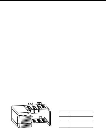
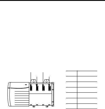
Use this figure to identify the external features of the module.
1
|
2 |
|
3 |
EtherNet/IP TM |
|
10/100 BASE T |
|
10 |
4 |
|
|
LNK1 LNK2 OK |
|
9 |
|
8
|
1 |
2 |
|
|
|
|
|
|
5 |
|
7 |
|
|
|
|
|
|
|
6 |
Item |
Description |
|
Item |
Description |
1 |
Top view |
|
6 |
Bottom view |
2 |
Rotary switches |
|
7 |
RJ45 (Ethernet) cable connectors |
|
|
|
|
(on underside of module) |
3 |
Side view |
|
8 |
Front view |
4 |
Backplane connector |
9 |
USB port |
|
5 |
MAC ID label (on opposite side |
10 |
Alphanumeric display and status |
|
|
of circuit board) |
|
|
indicators |
Publication 1756-IN612B-EN-P - December 2009
7
Software Requirements
You must have the following versions of software.
Module |
Software |
Version |
|
|
|
|
|
|
|
1756-EN2TR |
RSLinx Classic |
2.55 or later |
|
|
|
|
|
|
|
|
RSLogix 5000 |
17.0x (supports revision 2 of module firmware only) |
|
|
|
|
|
||
|
|
If you are using version 17.01 of RSLogix 5000 software, you need to download the |
|
|
|
|
add-on-profile. Download it from |
|
|
|
|
http://www.rockwellautomation.com/support/controlflash/LogixProfiler.asp |
|
|
|
|
or |
|
|
|
|
|
|
|
|
|
18 or later (supports revision 2 and later revisions of module firmware) |
|
|
|
|
|
|
|
1756-EN3TR |
RSLinx Classic |
2.56 or later |
|
|
|
|
|||
|
|
|
|
|
|
RSLogix 5000 |
18 or later |
|
|
|
|
|
||
|
|
|
|
|
Before You Begin
Before you install the module, you must install and connect a ControlLogix chassis and power supply.
1 |
2 |
Item |
Description |
|
|
||
|
|
1 |
Power supply |
|
|
2 |
1756-A4 chassis |
|
20805-M |
|
|
Publication 1756-IN612B-EN-P - December 2009
8
To install these products, refer to these publications.
Chassis Type |
Chassis Installation Instructions |
Power Supply |
Power Supply Installation |
|
|
|
Instructions |
|
|
|
|
1756-A4/B |
Publication 1756-IN080 |
1756-PA72/C, |
Publication 1756-IN613 |
1756-A7/B |
|
1756-PB72/B, |
|
1756-A10/B |
|
1756-PA75/B, |
|
1756-A13/B |
|
1756-PB75/B |
|
|
|
|
|
Determine Module Slot Location
Install the module in any slot in the ControlLogix chassis. You can install multiple 1756-EN2TR or 1756-EN3TR modules in the same chassis. The following figure shows chassis slot numbering in a 4-slot chassis. Slot 0 is the first slot and is always the leftmost slot in the rack.
3 |
5 |
|
|
|
4 |
6 |
|
Item |
Description |
|
|
|
|
|
|
|
|
1 |
Power supply |
|
|
|
2 |
Chassis |
|
|
|
3 |
Slot 0 |
1 |
|
2 |
4 |
Slot 1 |
|
|
|
||
|
|
|
5 |
Slot 2 |
|
|
|
6 |
Slot 3 |
|
20806 |
|
|
|
Set the Network Address
The module is shipped with the rotary switches set to 999 and BOOTP enabled. You can set the network Internet Protocol (IP) address three ways.
•Use the rotary switches on the top of the module.
•Use a BOOTP server or Dynamic Host Configuration Protocol (DHCP) server.
•Use Rockwell Automation RSLinx Classic or RSLogix 5000 software.
Publication 1756-IN612B-EN-P - December 2009
9
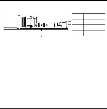
Use the Rotary Switches
|
Item |
Description |
|
1 |
2 |
|
|
1 |
Front of module |
||
|
|||
|
2 |
Top of module |
|
|
3 |
Rotary switches |
|
|
31587 |
|
|
|
3 |
|
The module reads the rotary switches first to determine if they are set to a valid number for the last portion of the IP address. Valid numbers range from 001…254.
When the switches are set to a valid number, the module’s IP address is 192.168.1.xxx (where xxx represents the number set on the switches). The module’s subnet mask is 255.255.255.0 and the gateway address is set to 0.0.0.0.
The module does not have a host name assigned, nor does it use any Domain Name System when using the rotary switch settings.
1.To reset the module to its initial out-of-the-box settings, reset the switches to 888 and cycle power.
IMPORTANT |
Do not use the 888 switch setting during normal module operation. |
|
|
|
|
|
|
2.After cycling power with the switches set to 888, remove the module and set the switches to their final value.
The software configuration determines the IP address when you set the rotary switches to:
•a value other than 888.
•the valid IP address values 001…254.
Publication 1756-IN612B-EN-P - December 2009
Loading...