


 Loading...
Pico Controllers
Bulletin 1760
User Manual
Important User Information Solid state equipment has operational characteristics differing from those of electromechanical equipment. Safety Guidelines for the Application,
Installation and Maintenance of Solid State Controls (Publication SGI-1.1 available from your local Rockwell Automation sales office or online at http://www.ab.com/manuals/gi) describes some important differences between solid state equipment and hard-wired electromechanical devices. Because of this difference, and also because of the wide variety of uses for solid state equipment, all persons responsible for applying this equipment must satisfy themselves that each intended application of this equipment is acceptable.
In no event will Rockwell Automation, Inc. be responsible or liable for indirect or consequential damages resulting from the use or application of this equipment.
The examples and diagrams in this manual are included solely for illustrative purposes. Because of the many variables and requirements associated with any particular installation, Rockwell Automation, Inc. cannot assume responsibility or liability for actual use based on the examples and diagrams.
No patent liability is assumed by Rockwell Automation, Inc. with respect to use of information, circuits, equipment, or software described in this manual.
Reproduction of the contents of this manual, in whole or in part, without written permission of Rockwell Automation, Inc. is prohibited.
Throughout this manual, when necessary we use notes to make you aware of safety considerations.
WARNING
Identifies information about practices or circumstances that can cause an explosion in a hazardous environment, which may lead to personal injury or death, property damage, or economic loss.
IMPORTANT
Identifies information that is critical for successful application and understanding of the product.
ATTENTION
Identifies information about practices or circumstances that can lead to personal injury or death, property damage, or economic loss. Attentions help you:
• identify a hazard
• avoid a hazard
• recognize the consequence
SHOCK HAZARD |
Labels may be located on or inside the equipment (e.g., |
||||
|
|
|
|
|
drive or motor) to alert people that dangerous voltage may |
|
|
|
|
|
be present. |
|
|
|
|
||
|
|
|
|
|
|
|
|
||||
|
|
|
|
|
|
|
|
|
|
|
Labels may be located on or inside the equipment (e.g., |
BURN HAZARD |
|||||
|
|
|
|
|
drive or motor) to alert people that surfaces may be |
|
|
|
|
|
dangerous temperatures. |
|
|
|
|
|
|
|
|
|
|
|
|

Summary of Changes
Catalog Number Release
History
The information below summarizes the changes to this manual since the last printing as publication 1760-UM001C-EN-P, April 2005.
To help you locate new and updated information in this release of the manual, we have included change bars as shown to the right of this paragraph.
The following table shows the history of Pico catalog numbers.
Description |
Released June 2000 |
Release August 2001 |
Release March 2005 |
|
|
|
|
|
|
|
|
120/240V ac Pico |
1760-L12AWA |
1760-L18AWA-EX |
1760-L18AWA-EXND |
|
|
|
|
|
|
|
|
|
1760-L12AWA-NC |
|
|
|
|
|
|
|
|
|
|
|
1760-L12AWA-ND |
|
|
|
|
|
|
|
|
|
|
|
1760-L18AWA |
|
|
|
|
|
|
|
|
|
|
24V dc Pico |
1760-L12BWB |
1760-L12BWB-ND |
1760-L12BBB |
|
|
|
|
|
|
|
|
|
1760-L12BWB-NC |
1760-L18BWB-EX |
1760-L12BBB-ND |
|
|
|
|
|
|
|
|
|
|
|
1760-L18BWB-EXND |
|
|
|
|
|
|
|
|
|
|
|
1760-L18DWD-EX |
|
|
|
|
|
|
|
|
|
|
|
1760-L20BBB-EX |
|
|
|
|
|
|
|
|
|
|
|
1760-L20BBB-EXND |
|
|
|
|
|
|
|
|
12V dc Pico |
|
1760-L12DWD |
1760-L18DWD-EXND |
|
|
|
|
|
|
|
|
|
|
|
1760-L12DWD-ND |
|
|
|
|
|
|
|
|
24V ac Pico |
|
|
1760-L12NWN |
|
|
|
|
|
|
||
|
|
|
|
|
|
|
|
|
1760-L12NWN-ND |
|
|
|
|
|
|
|
|
|
|
|
|
|
|
|
|
|
1760-L18NWN-EX |
|
|
|
|
|
|
|
|
|
|
|
|
|
|
|
|
|
1760-L18NWN-EXND |
|
|
|
|
|
|
|
|
|
|
|
|
|
|
Expansion Modules |
|
1760-IA12XOW6I |
1760-IA12XOW4I |
|
|
|
|
|
|
|
|
|
|
1760-IB12XOB8 |
1760-IB12XOW6I |
|
|
|
|
|
|
|
|
Expansion Module Connector(1) |
|
1760-RPLCONN |
|
|
|
Memory Modules |
1760-MM1 |
|
1760-MM2B |
|
|
|
|
|
|
|
|
|
1760-MM2 |
|
|
|
|
|
|
|
|
|
|
Input/Output Simulator |
1760-SIM |
|
|
|
|
|
|
|
|
|
|
Programming Software |
1760-PICOSOFT |
|
|
|
|
|
|
|
|
|
|
Programming Cable |
1760-CBL-PM02 |
|
|
|
|
|
|
|
|
|
|
(1) Included with expansion module. Catalog Number is listed as a replacement part.
Publication 1760-UM001D-EN-P - September 2005

Summary of Changes |
2 |
|
|
New Information
The table below lists sections where new information has been added.
For This New Information |
See |
|
|
Changed Catalog Number 1760-L12NWA and 1760-L18NWA to |
Throughout |
1760-L12NWN and 1760-L18NWN. |
manual |
|
|
Changed inputs to 24V ac. |
page A-5 |
|
|
Publication 1760-UM001D-EN-P - September 2005

|
Table of Contents |
|
Preface |
Who Should Use this Manual. . . . . . . . . . . . . . . . . . . |
Preface-1 |
|
Purpose of this Manual . . . . . . . . . . . . . . . . . . . . . . . |
Preface-1 |
|
Common Techniques Used in this Manual . . . . . . . . . |
Preface-2 |
|
Rockwell Automation Support . . . . . . . . . . . . . . . . . . |
Preface-3 |
|
Chapter 1 |
|
System Overview |
Overview . . . . . . . . . . . . . . . . . . . . . . . . . . . . . . . . . |
. . . . 1-1 |
|
Hardware Versions . . . . . . . . . . . . . . . . . . . . . . . . . . |
. . . . 1-2 |
|
Operating Principles . . . . . . . . . . . . . . . . . . . . . . . . . . |
. . . 1-6 |
|
Chapter 2 |
|
Installation |
Prevent Electrical Shock . . . . . . . . . . . . . . . . . . . . . . . |
. . . 2-1 |
|
European Communities (EC) Directive Compliance . . . |
. . . 2-2 |
|
Connect the Expansion Module . . . . . . . . . . . . . . . . . . |
. . . 2-3 |
|
Mount the Pico Controller . . . . . . . . . . . . . . . . . . . . . . |
. . . 2-3 |
|
Install the Remote Processor . . . . . . . . . . . . . . . . . . . . |
. . . 2-6 |
|
Wire Terminals . . . . . . . . . . . . . . . . . . . . . . . . . . . . . . |
. . . 2-8 |
|
Connect the Incoming Power . . . . . . . . . . . . . . . . . . . |
. . . 2-9 |
|
Use Surge Suppressors . . . . . . . . . . . . . . . . . . . . . . . . |
. . . 2-12 |
|
Connect the Inputs . . . . . . . . . . . . . . . . . . . . . . . . . . . |
. . . 2-14 |
|
Connect Outputs. . . . . . . . . . . . . . . . . . . . . . . . . . . . . |
. . . 2-22 |
|
Connect Relay Outputs . . . . . . . . . . . . . . . . . . . . . . . . |
. . . 2-22 |
|
Connect Transistor Outputs . . . . . . . . . . . . . . . . . . . . . |
. . . 2-24 |
|
Chapter 3 |
|
Commission the Pico |
Power On Unit . . . . . . . . . . . . . . . . . . . . . . . . . . . . . . |
. . . 3-1 |
|
Set the Menu Language . . . . . . . . . . . . . . . . . . . . . . . . |
. . . 3-2 |
|
Modes of Operation . . . . . . . . . . . . . . . . . . . . . . . . . . |
. . . 3-3 |
|
Create a Circuit Diagram (Program) . . . . . . . . . . . . . . . |
. . . 3-4 |
|
Chapter 4 |
|
Draw a Circuit Diagram with Pico |
Pico Operation . . . . . . . . . . . . . . . . . . . . . . . . . . . . . . |
. . . 4-1 |
|
Work with Contacts and Relays . . . . . . . . . . . . . . . . . . |
. . . 4-8 |
|
Function Relay Types . . . . . . . . . . . . . . . . . . . . . . . . . |
. . . 4-19 |
|
Example with Timing and Counter Relays . . . . . . . . . . |
. . . 4-21 |
|
Timing Relays . . . . . . . . . . . . . . . . . . . . . . . . . . . . . . . |
. . . 4-26 |
|
Counter Relays . . . . . . . . . . . . . . . . . . . . . . . . . . . . . . |
. . . 4-32 |
|
High Speed Counters . . . . . . . . . . . . . . . . . . . . . . . . . |
. . . 4-36 |
|
Time Switch . . . . . . . . . . . . . . . . . . . . . . . . . . . . . . . . |
. . . 4-42 |
|
Analog Comparators . . . . . . . . . . . . . . . . . . . . . . . . . . |
. . . 4-47 |
|
Text Display . . . . . . . . . . . . . . . . . . . . . . . . . . . . . . . . |
. . . 4-50 |
|
Jumps. . . . . . . . . . . . . . . . . . . . . . . . . . . . . . . . . . . . . |
. . . 4-53 |
|
Example Programs . . . . . . . . . . . . . . . . . . . . . . . . . . . |
. . . 4-55 |
Publication 1760-UM001D-EN-P - September 2005

Table of Contents ii
Chapter 5
Save and Load Circuit Diagrams |
Interface to Memory Module and Programming Cable |
. . . . 5-1 |
|
Memory Module . . . . . . . . . . . . . . . . . . . . . . . . . . . . |
. . . . 5-2 |
|
PicoSoft . . . . . . . . . . . . . . . . . . . . . . . . . . . . . . . . . . |
. . . . 5-5 |
|
Chapter 6 |
|
Pico System Settings |
Password Protection . . . . . . . . . . . . . . . . . . . . . . . . . |
. . . . 6-1 |
|
Change the Menu Language . . . . . . . . . . . . . . . . . . . |
. . . . 6-6 |
|
Change Parameters . . . . . . . . . . . . . . . . . . . . . . . . . . |
. . . . 6-7 |
|
Set Date, Time, and Daylight Saving Time . . . . . . . . . |
. . . . 6-9 |
|
Change Between Winter/Summer Time |
|
|
(Daylight Saving Time) . . . . . . . . . . . . . . . . . . . . . . . |
. . . . 6-10 |
|
Activate Debounce (Input Delay). . . . . . . . . . . . . . . . |
. . . . 6-10 |
|
Activate and Deactivate P-Buttons . . . . . . . . . . . . . . . |
. . . . 6-11 |
|
Start-Up Behavior . . . . . . . . . . . . . . . . . . . . . . . . . . . |
. . . . 6-12 |
|
Set Cycle Time . . . . . . . . . . . . . . . . . . . . . . . . . . . . . |
. . . . 6-14 |
|
Retention . . . . . . . . . . . . . . . . . . . . . . . . . . . . . . . . . |
. . . . 6-15 |
|
Display Device Information . . . . . . . . . . . . . . . . . . . . |
. . . . 6-17 |
|
Chapter 7 |
|
Retention |
What is Retention?. . . . . . . . . . . . . . . . . . . . . . . . . . . |
. . . . 7-1 |
|
Set Retention . . . . . . . . . . . . . . . . . . . . . . . . . . . . . . |
. . . . 7-2 |
|
Delete Retentive Actual Values . . . . . . . . . . . . . . . . . |
. . . . 7-2 |
|
Transfer Retentive Behavior. . . . . . . . . . . . . . . . . . . . |
. . . . 7-3 |
|
Retentive Auxiliary Relays (Markers) . . . . . . . . . . . . . |
. . . . 7-4 |
|
Retentive Timing Relays . . . . . . . . . . . . . . . . . . . . . . |
. . . . 7-8 |
|
Retentive Up/Down Counters C7 and C8 . . . . . . . . . . |
. . . . 7-14 |
|
Chapter 8 |
|
Inside Pico |
Circuit Diagram Cycle . . . . . . . . . . . . . . . . . . . . . . . . |
. . . . 8-1 |
|
Determine Cycle Time of Circuit Diagrams . . . . . . . . . |
. . . . 8-3 |
|
Delay Times for Inputs and Outputs . . . . . . . . . . . . . |
. . . . 8-7 |
|
Chapter 9 |
|
Use of Expansion Modules |
Overview . . . . . . . . . . . . . . . . . . . . . . . . . . . . . . . . . |
. . . . 9-1 |
|
Operation . . . . . . . . . . . . . . . . . . . . . . . . . . . . . . . . . |
. . . . 9-2 |
|
Module Status Example . . . . . . . . . . . . . . . . . . . . . . . |
. . . . 9-5 |
|
Chapter 10 |
|
Troubleshoot Your Controller |
Messages from the Pico System . . . . . . . . . . . . . . . . . |
. . . . 10-1 |
|
Possible Situations When Creating Circuit Diagrams . . |
. . . . 10-2 |
|
Event . . . . . . . . . . . . . . . . . . . . . . . . . . . . . . . . . . . . |
. . . . 10-3 |
Publication 1760-UM001D-EN-P - September 2005

|
|
Table of Contents iii |
|
|
|
|
Chapter 11 |
|
DC Simulator |
Description . . . . . . . . . . . . . . . . . . . . . . . . . . . . |
. . . . . . . . 11-1 |
|
Installation Guidelines. . . . . . . . . . . . . . . . . . . . |
. . . . . . . . 11-2 |
|
Appendix A |
|
Specifications |
Physical Specifications. . . . . . . . . . . . . . . . . . . . |
. . . . . . . . A-1 |
|
Environmental Specifications . . . . . . . . . . . . . . . |
. . . . . . . . A-1 |
|
Electrical Specifications . . . . . . . . . . . . . . . . . . . |
. . . . . . . . A-2 |
|
Power Supply . . . . . . . . . . . . . . . . . . . . . . . . . . |
. . . . . . . . A-3 |
|
Inputs. . . . . . . . . . . . . . . . . . . . . . . . . . . . . . . . |
. . . . . . . . A-5 |
|
Outputs . . . . . . . . . . . . . . . . . . . . . . . . . . . . . . |
. . . . . . . A-10 |
|
Cycle Time . . . . . . . . . . . . . . . . . . . . . . . . . . . . |
. . . . . . . A-13 |
|
Dimensions. . . . . . . . . . . . . . . . . . . . . . . . . . . . |
. . . . . . . A-14 |
Appendix B
Circuit Diagram Form
Glossary
Index
Publication 1760-UM001D-EN-P - September 2005

Table of Contents |
iv |
|
|
Publication 1760-UM001D-EN-P - September 2005

Preface
Who Should Use this Manual
Purpose of this Manual
Read this preface to familiarize yourself with the rest of the manual. It provides information concerning:
•who should use this manual
•the purpose of this manual
•related documentation
•conventions used in this manual
•Rockwell Automation support
Use this manual if you are responsible for designing, installing, programming, or troubleshooting control systems that use Pico controllers.
You should have a basic understanding of electrical circuitry and familiarity with relay logic. If you do not, obtain the proper training before using this product.
This manual is a reference guide for Pico controllers. It describes the procedures you use to install, wire, and troubleshoot Pico.
Refer to publication 1760-GR001, Pico Controller Getting Results Manual for a basic overview of Pico and an introduction to Pico programming.
Publication 1760-UM001D-EN-P - September 2005

Preface |
2 |
|
|
Related Documentation
The following documents contain additional information concerning
Rockwell Automation products. To obtain a copy, contact your local
Rockwell Automation office or distributor.
|
|
For |
Read this Document |
Document Number |
|
|
|
|
|
|
|
A basic overview of Pico and an introduction to Pico programming. |
Pico Controller Getting Results |
1760-GR001 |
|
|
|||
|
|
|
Manual |
|
|
|
|
|
|
|
|
In-depth information on grounding and wiring Allen-Bradley |
Allen-Bradley Programmable |
1770-4.1 |
|
|
programmable controllers |
Controller Grounding and Wiring |
|
|
|
|
Guidelines |
|
|
|
|
|
|
|
|
A description of important differences between solid-state |
Application Considerations for |
SGI-1.1 |
|
|
programmable controller products and hard-wired electromechanical |
Solid-State Controls |
|
|
|
devices |
|
|
|
|
|
|
|
|
|
An article on wire sizes and types for grounding electrical equipment |
National Electrical Code - Published by the National Fire |
|
|
|
|
Protection Association of Boston, MA. |
|
|
|
|
|
|
|
|
A complete listing of current documentation, including ordering |
Allen-Bradley Publication Index |
SD499 |
|
|
instructions. Also indicates whether the documents are available on |
|
|
|
|
CD-ROM or in multi-languages. |
|
|
|
|
|
|
|
|
|
A glossary of industrial automation terms and abbreviations |
Allen-Bradley Industrial Automation |
AG-7.1 |
|
|
|
Glossary |
|
|
|
|
|
|
Common Techniques Used in this Manual
The following conventions are used throughout this manual:
•Bulleted lists such as this one provide information, not procedural steps.
•Numbered lists provide sequential steps or hierarchical information.
Publication 1760-UM001D-EN-P - September 2005
Preface 3
Rockwell Automation
Support
Rockwell Automation offers support services worldwide, with over 75 Sales/Support Offices, 512 authorized Distributors and 260 authorized Systems Integrators located throughout the United States alone, plus Rockwell Automation representatives in every major country in the world.
Local Product Support
Contact your local Rockwell Automation representative for:
•sales and order support
•product technical training
•warranty support
•support service agreements
Technical Product Assistance
If you need to contact Rockwell Automation for technical assistance, please review the Troubleshooting section on page 10-1 in this manual first. Then call your local Rockwell Automation representative.
You can also find a local Rockwell Automation Technical Support contact at:
• http://support.automation.rockwell.com/contactinformation/
Your Questions or Comments on this Manual
If you find a problem with this manual, or you have any suggestions for how this manual could be made more useful to you, please contact us at the address below:
Rockwell Automation
Control and Information Group
Technical Communication, Dept. A602V
P.O. Box 2086
Milwaukee, WI 53201-2086
or visit our internet page at:
http://www.ab.com/pico or http://www.rockwellautomation.com
Publication 1760-UM001D-EN-P - September 2005

Preface 4
Publication 1760-UM001D-EN-P - September 2005

Chapter 1
System Overview
Overview
Pico is an electronic control relay with built-in logic, timer, counter, and real-time clock functions. Pico is a control and input device that can perform a variety of tasks in building and machine applications.
Pico is programmed using ladder diagrams. Each programming element is entered directly via the Pico display. For example, you can:
•connect make and break contacts in series and in parallel,
•connect output relays and markers,
•define outputs as relays, flip-flop relays or latching relays,
•select timing relays with different functions,
•assign eight up and down counters,
•display text with variables,
•track the flow of current in the program, and
•load, save and password-protect programs.
Most controllers also offer a real-time clock, allowing up to 32 separate on and off times.
The dc versions can receive analog signals at two inputs and evaluate the signals with eight analog comparators.
If you prefer to program Pico from a PC, use PicoSoft programming software. PicoSoft allows you to create and test your programs on the PC. It also enables you to print out your programs in DIN, ANSI or Pico format.
Publication 1760-UM001D-EN-P - September 2005

1-2 System Overview
Hardware Versions
Pico Controllers
1
2
7 |
Del |
Alt |
|
|
3 |
8 |
|
4 |
|
|
|
|
|
Esc |
Ok |
7 |
|
|
|
|
Del |
Alt |
|
5 |
|
|
|
|
||
8 |
|
|
|
6 |
|
Esc |
Ok |
|
|
|
|
|
|
|
|
|
|
|
5 |
8
3
5
Item |
Description |
|
|
1 |
Incoming Power |
|
|
2 |
Inputs |
|
|
3 |
Status LED |
|
|
4 |
Buttons |
|
|
5 |
Socket for memory module or PC interface cable |
|
|
6 |
Outputs |
|
|
7 |
LCD display |
|
|
8 |
Write-On Surface |
|
|
Publication 1760-UM001D-EN-P - September 2005

System Overview |
1-3 |
|
|
Pico controllers are available for 12V dc, 24V dc, 24V ac and 120/240V ac operation and come in both 12-I/O and 18-I/O sizes. Pico is available with and without a real-time clock, and with and without a display and keypad. See the following table for details.
Catalog Number |
Inputs |
Outputs |
Line Power |
Real Time |
Display and |
Analog |
|
|
|
|
|
|
|
|
Clock |
Keypad |
|
|
|
|
|
|
|
|
|
|
|
|
|
1760-L12AWA |
8 (100 to 240V ac) |
4 |
(relay) |
100 to 240V ac |
Yes |
Yes |
No |
|
|
|
|
|
|
|
|
|
|
|
|
1760-L12AWA-NC(1) |
|
|
|
|
No |
Yes |
|
|
|
1760-L12AWA-ND(2) |
|
|
|
|
Yes |
No |
|
|
|
1760-L18AWA |
12 (100 to 240V ac) |
6 |
(relay) |
|
Yes |
Yes |
|
|
|
|
|
|
|
|
|
|
|
|
|
1760-L18AWA-EX(3) |
|
|
|
|
Yes |
Yes |
|
|
|
1760-L18AWA-EXND(2)(3) |
|
|
|
|
Yes |
No |
|
|
|
1760-L12BWB |
8 (24V dc) |
4 |
(relay) |
24V dc |
Yes |
Yes |
2 (0 to 10V dc) |
|
|
|
|
|
|
|
|
|
|
|
|
1760-L12BWB-NC(1) |
|
|
|
|
No |
Yes |
|
|
|
1760-L12BWB-ND(2) |
|
|
|
|
Yes |
No |
|
|
|
1760-L12BBB |
|
4 |
(MOSFET) |
|
Yes |
Yes |
2 (0 to 10V dc) |
|
|
|
|
|
|
|
|
|
|
|
|
1760-L12BBB-ND |
|
|
|
|
Yes |
No |
|
|
|
|
|
|
|
|
|
|
|
|
|
1760-L12NWN |
8 (24V ac) |
4 |
(relay) |
24V ac |
Yes |
Yes |
|
|
|
|
|
|
|||||||
|
|
|
|
|
|
|
|
|
|
1760-L12NWN-ND |
|
|
|
|
Yes |
No |
|
|
|
|
|
|
|
|
|
|
|||
|
|
|
|
|
|
|
|
|
|
1760-L12DWD |
8 (12V dc) |
|
|
12V dc |
Yes |
Yes |
|
|
|
|
|
|
|
|
|
|
|
|
|
1760-L12DWD-ND |
|
|
|
|
Yes |
No |
|
|
|
|
|
|
|
|
|
|
|
|
|
1760-L18BWB-EX(3) |
12 (24V dc) |
6 |
(relay) |
24V dc |
Yes |
Yes |
|
|
|
1760-L18BWB-EXND(2)(3) |
|
6 |
(relay) |
|
Yes |
No |
2 (0 to 10V dc) |
|
|
1760-L20BBB-EX(3) |
|
8 |
(MOSFET) |
|
Yes |
Yes |
4 (0 to 10V dc) |
|
|
1760-L20BBB-EXND(2)(3) |
|
8 |
(MOSFET) |
|
Yes |
No |
|
|
|
1760-L18DWD-EX(3) |
12 (12V dc) |
6 |
(relay) |
12V dc |
Yes |
Yes |
|
|
|
1760-L18DWD-EXND(2)(3) |
|
6 |
(relay) |
12V dc |
Yes |
No |
|
|
|
1760-L18NWN-EX(3) |
12 (24V ac) |
6 |
(relay) |
24V ac |
Yes |
Yes |
4 (0 to 10V dc) |
|
|
|
|
||||||||
|
|
|
|
|
|
|
|
|
|
1760-L18NWN-EXND(2)(3) |
12 (24V ac) |
6 |
(relay) |
|
Yes |
No |
|
|
|
|
|
|
|
||||||
|
|
|
|
|
|
|
|
|
|
(1)NC = no real time clock
(2)ND = no display
(3)EX = suitable for use with expansion modules
Publication 1760-UM001D-EN-P - September 2005

1-4 System Overview
Expansion Modules
2 |
1 |
|
3
5
3
4
Item |
Description |
|
|
1 |
Incoming Power |
|
|
2 |
Inputs |
|
|
3 |
Write-On Surface |
|
|
4 |
Outputs |
|
|
5 |
Status LED |
|
|
Use Pico expansion modules with Pico ’-EX’ models to increase your
I/O capacity. The following modules are available.
Catalog Number |
Inputs |
Outputs |
Line Power |
|
|
|
|
|
|
1760-IA12XOW6I |
12 |
(100 to 240V ac) |
6 (relay) |
100 to 240V ac |
|
|
|
|
|
1760-IA12XOW4I |
12 |
(100 to 240V ac) |
4 (relay) |
100 to 240V ac |
|
|
|
|
|
1760-IB12XOW6I |
12 |
(24V dc) |
6 (relay) |
24V dc |
|
|
|
|
|
1760-IB12XOB8 |
12 |
(24V dc) |
8 (transistor) |
24V dc |
|
|
|
|
|
1760-OW2 |
- |
|
2 (relay) |
24V dc |
|
|
|
|
|
Publication 1760-UM001D-EN-P - September 2005

System Overview |
1-5 |
|
|
Expansion modules connect directly to the Pico controller as shown below.
Expansion Module Connector(1) (replacement part 1760-RPLCONN)
Pico Controller: |
Expansion Module: |
1760-L18AWA-EX |
1760-IA12XOW6I |
1760-L18BWB-EX |
1760-IB12XOB8 |
1760-L18AWA-EXND |
1760-IA12XOW4IF |
1760-L18BWB-EXND |
1760-IB12XOW6I |
1760-L18DWD-EX |
1760-OW2 |
1760-L20BBB-EX |
(1) Included with expansion module. Catalog |
1760-L20BBB-EXND |
Number is listed as a replacement part. |
ATTENTION |
Electrical isolation is provided between the Pico |
|||
controller and the expansion module as follows: |
||||
|
|
|
||
|
|
|
||
|
|
|
• Basic Isolation: 400V ac (+10%)(1) |
|
|
|
|
• Reinforced Isolation 240V ac (+10%)(2) |
|
|
|
|
||
|
|
|
||
|
|
|
The controller and expansion units may be |
|
|
|
|
destroyed if the potential between them exceeds the |
|
|
|
|
Basic Isolation value provided. This may cause your |
|
|
|
|
entire system or machine to malfunction. |
|
(1)Basic Insulation - An insulation system which provides a minimal level of protection against electric shock up to a stated voltage level. Refer to EN 61131-2 for additional information.
(2)Reinforced Insulation - An insulation system comprised of basic and supplemental insulation. This provides protection against electric shock up to a stated voltage level and is tolerant of a single fault. Refer to EN 61131-2 for additional information.
TIP |
The Pico controller and the expansion module can |
|
be of different voltage types. |
||
|
||
|
Publication 1760-UM001D-EN-P - September 2005
1-6 System Overview
Operating Principles
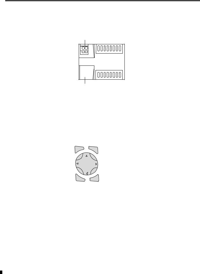
Remote Processor
Remote Processor Features
1
2
1.24V dc Voltage supply
2.Interface Terminal (with cover) for connecting cable
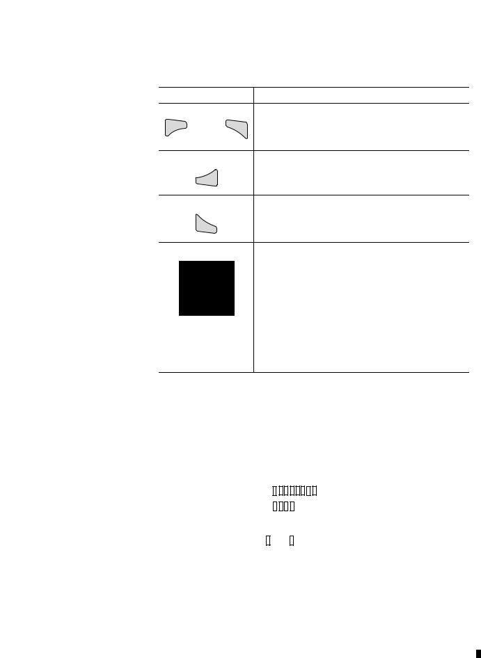
Operating Buttons
Del |
Alt |
Esc |
Ok |
Button |
Function |
|
|
|
|
Del |
Delete object in the circuit diagram |
|
|
|
|
Alt |
Special functions in the circuit diagram |
|
|
|
|
Cursor |
Move cursor |
|
Buttons |
|
|
Select menu item |
||
|
||
|
|
|
|
Choose contact numbers, values, times, etc. |
|
|
|
|
Ok |
Next menu level, store your entry |
|
|
|
|
Esc |
Previous menu level, cancel your entry |
|
|
|
Publication 1760-UM001D-EN-P - September 2005
System Overview |
1-7 |
|
|
Using Menus to Choose Values
Press
Del and
together
Ok
Esc
To
Show system menu
Alt
•Go to next menu level.
•Select menu item.
•Store your entry.
•Return to last menu level.
•Cancel your entry since the last Ok.
•Change menu item.
•Change value.
•Change position.
Cursor Button Set to P-Button Function (if enabled)
•Left Arrow = Input P1
•Right Arrow = Input P3
•Up Arrow = Input P2
•Down Arrow = Input P4
Selecting the Main and System Menus
1760-L12xxx Status Display
Inputs |
|
|
I12345678 |
|
|
Weekday |
||||||
|
|
|||||||||||
|
|
|
|
|
|
|
|
|
MO |
|
|
|
|
|
|
|
|
|
|
|
|
|
|
||
|
|
|
|
|
|
|
|
|
|
|||
Outputs |
|
|
|
|
|
|
|
|
12:50 |
|
|
Time |
|
|
|
|
|
|
|
|
|
|
|||
|
|
|
|
|
|
|
|
|
||||
|
|
Q1234 |
RUN |
|
|
RUN/STOP Mode |
||||||
|
|
|
|
|
||||||||
|
|
|
|
On |
Off |
|
|
|||||
|
|
|
|
|
|
|||||||
Publication 1760-UM001D-EN-P - September 2005

1-8 System Overview
1760-L18xxx Status Display
Inputs |
|
|
12........... |
|
|
|
|
|
|
|
|||||
Weekday/Time |
|
|
MO 02:00 |
|
|
|
|
|
|
|
|
|
|||
Outputs |
|
|
|
..34.... RUN |
|
|
RUN/STOP Mode |
|
|
|
|||||
|
|
||||||
|
|
|
|
|
|
|
|
|
|
Inputs 1 and 2 ON |
|
|
|||
|
|
Outputs 3 and 4 ON |
|
|
|||
1760-L18xxx-EX and 1760-L20xxx Status Display for Expansion Module
Inputs
Expansion
Weekday/Time
Outputs
1..........12 |
|
|
|
|
RS |
AC P- |
|
|
AC Expansion OK/P Buttons |
|
||||
MO |
10:42 ST |
|
|
|
1.......8 |
|
|
|
|
RS = Expansion functioning correctly
AC = AC expansion functioning correctly
DC = DC expansion correctly
LED Indicators
Catalog numbers 1760-L12AWA-ND, 1760-L12BWB-ND, 1760-L18xxx, 1760-L20BBB-EXND, 1760-IA12XOW6I, 1760-IB12XOB8, 1760-IA12XOW4I and 1760-IB12XOW6I all feature an LED indicator on the front that shows the status of the incoming power as well as Run or Stop status.
LED Indicator Status |
Indicates |
|
|
LED OFF |
No power |
|
|
LED continuously lit |
Power present, Stop mode |
|
|
LED flashing |
Power present, Run mode |
|
|
Publication 1760-UM001D-EN-P - September 2005
System Overview |
1-9 |
|
|
|
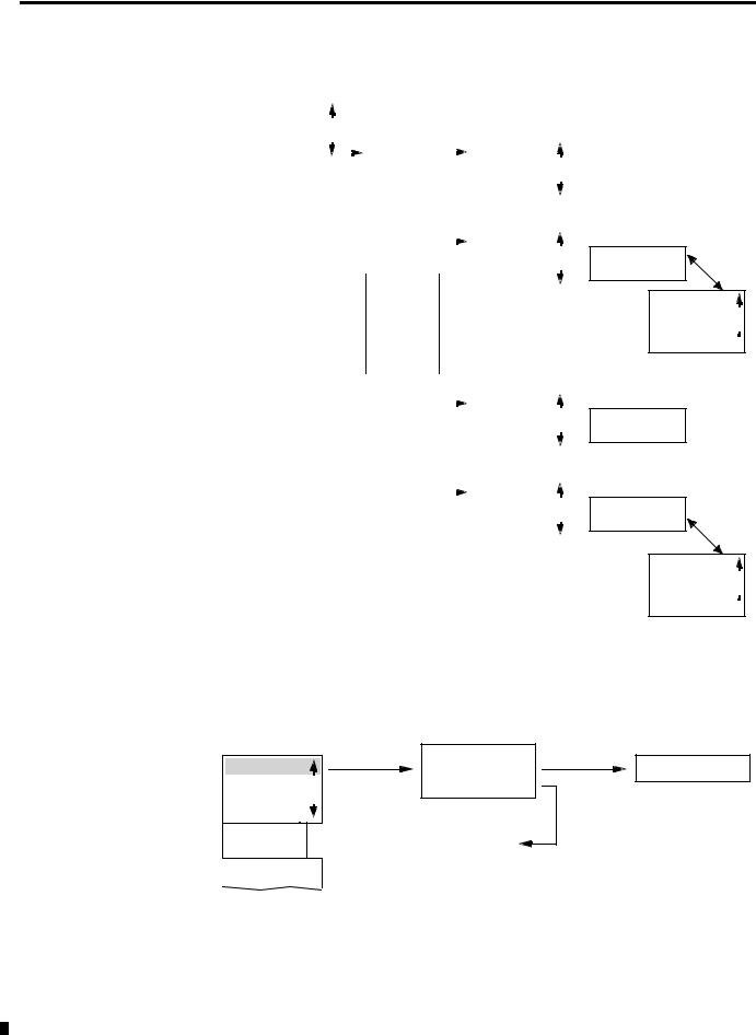
Menu Structure |
|
|
|
|
Main Menu Without Optional Password Protection |
|
||
|
|
|
STOP: Circuit diagram menu |
|
|
|
|
RUN: Power flow display |
|
PROGRAM... |
RUN |
Circuit Diagram |
Parameter |
|
|
||||
STOP RUN |
å |
STOP |
|
Display |
PARAMETER |
|
|
|
|
|
|
|
|
|
|
INFO... |
|
|
|
|
PROGRAM |
|
|
|
|
|
|
|
|
|
|
|
|
|
|
|
|
|
|
|
|
|
|
|
Parameters |
|||||||||||
|
|
|
|
|
|
|
|
|
|
|
|
|
|
|
|
|
|
|
|
|
|
|
|
|
|
|
|
||||||||||||||
|
SET CLOCK |
|
|
|
|
|
DELETE PROG |
|
|
|
|
|
|
|
|
|
|
|
|
|
|
|
|
|
|
|
|||||||||||||||
|
|
|
|
|
|
|
CARD ... |
|
|
|
|
|
|
|
|
|
|
|
|
|
|
|
|
|
|
|
|||||||||||||||
|
|
|
|
|
|
|
|
|
|
|
|
|
|
|
|
|
|
|
|
|
|
|
|
|
|
||||||||||||||||
|
|
|
|
|
|
|
|
|
|
|
|
|
|
|
|
|
|
|
|
|
|
|
|
|
|
|
|
|
|
|
|
|
|
|
|
|
|
|
|
|
|
|
|
|
|
|
|
|
|
|
PROGRAM |
|
|
|
|
|
|
|
|
|
|
|
|
|
|
|
|
|
|
|
|
|
|
|
|
|
|||||||
|
|
|
|
|
|
|
|
|
|
|
|
|
|
|
|
|
|
|
|
|
|
|
|
|
|
|
|
|
|
|
|
||||||||||
|
|
|
|
|
|
|
|
|
DELETE PROG |
|
|
|
|
|
|
|
DELETE ? |
|
|
|
|
|
|
|
|
|
|
|
|
|
|
||||||||||
|
|
|
|
|
|
|
|
|
|
|
|
|
|
|
|
|
|
|
|
|
|
|
|
|
|||||||||||||||||
|
|
|
|
|
|
|
|
|
CARD ... |
|
|
|
|
|
|
|
|
|
|
|
|
|
|
|
|
|
|
|
|
|
|
|
|||||||||
|
|
|
|
|
|
|
|
|
|
|
|
|
|
|
|
|
|
|
|
|
|
|
|
|
|
|
|||||||||||||||
|
|
|
|
|
|
|
|
|
|
|
|
|
|
|
|
|
|
|
|
|
|
|
|
|
|
|
|
|
|
|
|
|
|
|
|
|
|
|
|||
|
|
|
|
|
|
|
|
|
|
PROGRAM |
|
|
|
|
|
|
|
|
|
|
|
|
|
|
|
|
|
|
|
|
|
|
|
||||||||
|
|
|
|
|
|
|
|
|
|
|
|
|
|
|
|
|
|
|
|
|
|
|
|
|
|
|
|
|
|
|
|
|
|
|
|||||||
|
|
|
|
|
|
|
|
|
|
DELETE PROG |
|
|
|
|
|
|
|
|
|
|
|
|
|
|
|
|
|
|
|
|
|
|
|||||||||
|
|
|
|
|
|
|
|
|
|
CARD ... |
|
|
|
|
|
DEVICE->CARD |
|
|
|
|
|
|
REPLACE ? |
|
|
||||||||||||||||
|
|
|
|
|
|
|
|
|
|
|
|
|
|
|
|
|
|
|
|
|
|
|
|
||||||||||||||||||
|
|
|
|
|
|
|
|
|
|
|
|
|
|
|
|
|
|
|
|
|
|
|
|
CARD->DEVICE |
|
|
|
|
|
|
|
|
|
|
|
|
|||||
|
|
|
|
|
|
|
|
|
|
|
|
|
|
|
|
|
|
|
|
|
|
|
|
|
|
|
|
|
|
|
|
|
|
|
|
||||||
|
|
|
|
|
|
|
|
|
|
|
|
|
|
|
|
|
|
|
|
|
|
|
|
DELETE CARD |
|
|
|
|
|
|
|
|
|||||||||
|
|
|
|
|
|
|
|
|
|
|
|
|
|
|
|
|
|
|
|
|
|
|
|
|
|
|
|
|
|
|
|
|
|
|
|
|
|
|
|||
|
|
|
|
|
|
|
|
|
|
|
|
|
|
|
|
|
|
|
|
|
|
|
|
|
DEVICE->CARD |
|
|
|
|
|
|
|
|
|
|
||||||
|
|
|
|
|
|
|
|
|
|
|
|
|
|
|
|
|
|
|
|
|
|
|
|
|
|
|
|
|
|
|
|
|
|
|
|||||||
|
|
|
|
|
|
|
|
|
|
|
|
|
|
|
|
|
|
|
|
|
|
|
|
|
|
|
|
|
|
REPLACE ? |
|
||||||||||
|
PROGRAM... |
|
|
|
|
|
|
|
|
|
|
|
|
|
|
|
|
|
|
|
|
|
|
CARD->DEVICE |
|
|
|
|
|
|
|||||||||||
|
|
|
|
|
|
|
|
|
|
|
|
|
|
|
|
|
|
|
|
|
|
|
|
|
|
|
|
|
|||||||||||||
|
STOP RUN |
|
|
|
|
RUN |
|
|
|
|
|
|
|
|
|
DELETE CARD |
|
|
|
|
|
|
|
|
|
|
|||||||||||||||
|
|
|
|
|
|
|
|
|
|
|
|
|
|
|
|
|
|
|
|
|
|
|
|
|
|
|
|||||||||||||||
|
|
|
|
|
|
|
|
|
|
|
|
|
|
|
|
|
|
|
|
|
|
|
|
|
|
|
|||||||||||||||
|
PARAMETER |
|
|
|
|
|
|
|
|
|
|
|
|
|
|
|
|
|
|
|
|
|
|
|
|
|
|
|
|
|
|
|
|
|
|
|
|
|
|
|
|
|
|
|
|
|
|
|
|
|
|
|
|
|
|
|
|
|
|
|
|
|
|
|
|
|
|
|
|
|
|
|
|
|
|
|
|
|
|
|
|
||
|
INFO... |
|
|
|
|
|
STOP |
|
|
|
|
|
|
|
|
|
|
|
|
|
DEVICE->CARD |
|
|
|
|
|
|
|
|
||||||||||||
|
|
|
|
|
|
|
|
|
|
|
|
|
|
CARD->DEVICE |
|
|
|
|
|
|
|
|
|||||||||||||||||||
|
|
|
|
|
|
|
|
|
|
|
|
|
|
|
|
|
|
|
|
|
|
|
|
|
|
|
|
|
|
|
|||||||||||
|
|
|
|
|
|
|
|
|
|
|
|
|
|
|
|
|
|
|
|
|
|
|
|
|
|
|
|
|
|
|
|
|
|||||||||
SET CLOCK
DELETE CARD  DELETE ?
|
PROGRAM... |
|
|
|
|
|
|
|
|
|
|
|
|
|
|
|
|
|
|
|
|
||
|
STOP RUN |
|
|
|
|
T1 X |
|
S |
+ |
|
|
|
|
T1 X |
S |
+ |
|
||||||
|
|
|
|
|
T2 Ü |
M:S |
+ |
|
|
|
|
S1 10.000 |
|
|
|||||||||
|
PARAMETER |
|
|
|
|
|
|
|
|
|
|
||||||||||||
|
|
|
|
|
C1 N |
|
|
|
|
|
+ |
|
|
|
|
|
|
||||||
|
|
|
|
|
|
|
|
|
|
|
|
|
|
S2 +0 |
|
|
|
|
|||||
|
INFO... |
|
|
|
|
|
|
|
|
|
|
|
|
|
|
|
|
|
|||||
|
|
|
|
|
O1 |
|
|
|
|
|
+ |
|
|
|
|
|
|
|
|
||||
|
|
|
|
|
|
|
|
|
|
|
|
|
|
T: |
|
|
|
|
|||||
|
SET CLOCK |
|
|
|
|
|
Parameter Display |
|
|
|
|
|
|
|
|
|
|||||||
|
|
|
|
|
|
|
|
|
|
Information Display of Device |
|||||||||||||
|
|
|
|
|
|
|
|
|
|
|
|
||||||||||||
|
|
|
|
|
|
|
|
|
|
|
|
|
|
|
|
|
|
||||||
|
PROGRAM... |
|
|
|
|
|
|
|
|
|
|
|
|
|
|
|
|
|
|
|
|
||
|
RUN |
|
|
|
|
|
|
|
|
|
|
|
|
|
|
|
|
|
|
|
|
||
|
PARAMETER |
|
|
|
|
|
|
|
|
|
|
|
|
|
|
|
|
|
|
|
|
||
|
INFO... |
|
|
|
DC TC LCD |
|
|
|
|
|
|
|
Display for |
|
|
|
|
||||||
|
|
|
|
|
|
|
|
|
|
|
|
|
|
||||||||||
|
|
|
|
|
|
|
OS: 1.00.027 |
|
|
|
|
|
|
|
|||||||||
|
SET CLOCK |
|
|
|
|
|
|
|
|
|
|
||||||||||||
|
|
|
|
|
|
|
CRC: 02752 |
|
|
|
Setting Clock |
|
|
|
|
||||||||
|
PROGRAM... |
|
|
|
|
|
|
|
|
|
|
|
|
|
|
|
|
|
|
|
|
|
|
|
RUN |
|
|
|
|
|
|
|
|
|
|
|
|
|
|
|
|
|
|
|
|
|
|
|
PARAMETER |
|
|
|
|
|
|
|
|
|
|
|
|
|
|
|
|
|
|
|
|||
|
INFO... |
|
|
|
|
|
|
|
|
|
|
HH:MM --:-- |
|
|
HH:MM 14:23 |
||||||||
|
|
|
|
|
|
|
|
|
|
DD.MM --.-- |
|
|
|
|
|||||||||
|
SET CLOCK |
|
|
|
|
SET CLOCK |
|
|
|
|
|
|
|
DD.MM 17.03 |
|||||||||
|
|
|
|
|
|
|
|
|
|
|
|
|
|
||||||||||
|
|
|
|
|
|
|
SUMMER TIME |
|
|
|
|
YEAR |
---- |
|
|
YEAR 2004 |
|||||||
|
|
|
|
|
|
|
|
|
|
|
|
|
|||||||||||
|
|
|
|
|
|
|
|
|
|
|
|
|
|
|
|
|
|
|
|
|
|
|
|
|
|
|
|
|
|
|
|
|
|
|
|
|
|
|
|
|
|
|
|
|
|
|
|
Publication 1760-UM001D-EN-P - September 2005
1-10 System Overview
Main Menu Setting Summer Time
PROGRAM... |
|
|
|
|
|
|
|
|
|
|
|
|
|
|
|
|
|
|
|
|
|
|
|
RUN |
|
|
|
|
|
|
|
|
|
|
|
PARAMETER |
|
|
|
|
|
|
|
|
|
|
|
INFO... |
|
|
|
SET CLOCK |
|
|
|
|
|
|
|
SET CLOCK |
|
|
|
SUMMER TIME |
|
|
|
|
NONE |
å |
|
|
|
|
|
|
|
|
|||||
|
|
|
|
|
|
|
|
|
|
RULE... |
|
|
|
|
|
|
|
|
|
|
|
|
|
|
|
|
|
|
|
|
|
|
|
EU |
|
|
|
|
|
|
|
|
|
|
|
GB |
|
|
|
|
|
|
|
|
|
|
|
US |
|
|
|
|
|
SET CLOCK |
|
|
|
||||
|
|
|
|
SUMMER TIME |
|
NONE |
|
||||
|
|
|
|
|
|
|
|
||||
|
|
|
|
|
|
|
|
|
|
RULE... |
|
|
|
|
|
|
|
|
|
|
|
EU |
|
|
|
|
|
|
|
|
|
|
|
GB |
|
|
|
|
|
|
|
|
|
|
|
US |
|
SET CLOCK |
|
|
|
|
||
SUMMER TIME |
|
|
|
NONE |
||
|
|
|
||||
|
|
|
|
|
|
RULE... |
|
|
|
|
|
|
EU |
|
|
|
|
|
|
GB |
|
|
|
|
|
|
US |
SET CLOCK |
|
|
||||
SUMMER TIME |
|
NONE |
||||
|
|
|
||||
|
|
|
|
|
|
RULE... |
|
|
|
|
|
|
EU |
|
|
|
|
|
|
GB |
|
|
|
|
|
|
US |
 SUMMER START
SUMMER END
AM |
-- |
HH:MM |
-- |
|
-- |
DD.MM:00.00 
HH.MM:00:00
DIFF: 0:00
 SUMMER START
SUMMER END
SUMMER START
 SUMMER END
AM |
-- |
HH:MM |
-- |
|
-- |
DD.MM:00.00 
HH.MM:00:00
DIFF: 0:00
Main Menu with Password Protection |
|
|
Main Menu |
Password Entry |
|
|
|
|
PASSWORD... Unlock |
Password |
DELETE ALL |
RUN |
|
Four Wrong |
PARAMETER |
|
Entries |
INFO... |
Correct Entry |
|
SET CLOCK |
|
|
PASSWORD... |
Status Display |
|
|
|
|
RUN |
|
|
Publication 1760-UM001D-EN-P - September 2005

System Overview |
1-11 |
|
|
System Menu
Password Entry
System |
|
|
|
|
Set Password |
|
|
|
|
|
|
|
|
|
|
|
|
|
|
|
|
|
|
|
|
|
|
|
|
|
|
|
|
|
|
|
|
|||||||||||||||
|
|
|
|
|
|
|
|
|
|
|
|
|
|
|
|
|
|
|
|
ENTER PASSW: |
|
|
|
|
|
CHANGE PW |
|
|
|
|
|
|||||||||||||||||||||
|
|
|
|
|
|
|
|
|
|
|
|
|
|
|
|
|
|
|
|
|
|
|
|
|
|
|
|
|
|
|
|
|
|
|
|
|||||||||||||||||
|
sECURITY... |
|
|
|
|
|
|
|
|
|
|
|
|
|
|
|
|
|
|
|
|
|
|
Password |
|
|
|
|
XXXX |
|
|
|
|
|
|
ACTIVATE PW |
|
|
|
|
|
|||||||||||
|
|
|
|
|
|
|
|
|
|
|
|
|
|
|
|
|
|
|
|
|
|
|
|
|
|
|
|
|
|
|
|
|
|
|
|
|
|
|||||||||||||||
SYSTEM... |
|
|
|
|
|
|
|
|
|
|
|
|
|
|
|
|
|
|
|
RANGE... |
|
|
|
|
|
|
|
|
|
|
|
|
|
|
|
|
|
|
||||||||||||||
|
|
|
|
|
|
|
|
|
|
|
|
|
|
|
|
|
|
|
|
|
|
|
|
|
|
|
|
|
|
|
|
|
|
|
|
|
|
|||||||||||||||
LANGUAGE ... |
|
|
|
Change Password |
|
|
|
|
|
|
|
|
|
|
|
|
|
|
|
|
|
|
|
|
|
|
|
|
|
|
|
|
|
|
|
|
||||||||||||||||
|
|
|
|
|
|
|
|
|
|
|
|
|
|
|
|
|
|
|
|
|
|
|
|
|
|
|
|
|
|
|
|
|
|
|
||||||||||||||||||
CONFIGURATOR |
|
|
|
|
|
|
|
|
|
|
|
|
|
|
|
|
|
|
|
|
|
|
|
|
|
|
|
|
|
|
|
|
|
|
|
|||||||||||||||||
|
|
|
|
|
|
|
|
|
|
|
|
|
|
|
|
|
|
|
|
|
|
|
|
|
|
|
|
|
|
|
|
|
|
|
||||||||||||||||||
|
|
|
|
|
|
|
|
|
|
|
|
|
|
|
|
|
|
|
|
|
|
|
|
ACTIVATE PW |
|
|
|
|
|
|
|
|
|
ENTER PASSW: |
|
|
|
|
CHANGE PW |
|
|
|
|
|||||||||
|
|
|
|
|
|
|
|
|
|
|
|
|
|
|
|
|
|
|
|
|
|
|
|
CHANGE PW |
|
|
|
|
|
|
|
|
|
XXXX |
|
|
|
|
|
|
ACTIVATE PW |
|
|
|
|
|||||||
|
|
|
|
|
|
|
|
|
|
|
|
|
|
|
|
|
|
|
|
|
|
|
|
|
|
|
|
|
|
|
|
|
|
|
|
|
|
|
|
|
|
|||||||||||
|
|
|
|
|
|
|
|
|
|
|
|
|
|
|
|
|
|
|
|
|
|
|
|
|
|
|
|
|
|
|
|
|
|
|
|
|
|
|
|
|
|
|
|
|
|
|
|
|||||
|
|
|
|
|
|
|
|
|
|
|
|
|
|
|
|
|
|
|
|
|
|
|
|
|
|
|
|
|
|
|
|
|
|
|
|
|
|
|
|
|
|
|
|
|
|
|
|
|
|
|
|
|
|
|
|
|
|
|
|
|
|
|
|
|
|
|
|
|
|
|
|
|
|
|
|
|
|
|
|
|
|
|
|
|
|
|
|
|
|
|
|
|
|
|
|
|
|
|
|
|
|
|
|
|
|
|
|
|
|
|
|
|
|
|
|
|
|
|
|
|
|
|
|
|
|
|
|
|
|
|
|
|
|
|
|
|
|
|
|
|
|
|
|
|
|
|
|
|
|
|
|
|
|
|
|
|
||
|
|
|
|
|
|
|
|
|
|
|
|
|
|
|
|
|
|
|
|
|
|
|
|
|
|
|
|
|
|
|
|
|
|
|
|
|
|
|
|
|
|
|
|
|
|
|
|
|
|
|
|
|
|
|
|
|
|
|
|
|
|
|
|
|
|
|
|
|
|
|
|
|
|
|
|
|
|
|
|
|
|
|
|
|
|
|
|
|
|
PROGRAM |
å |
|
|
|
|
|
|
|
PROGRAM |
å |
|
|
|||
|
|
|
|
|
|
|
|
|
|
|
|
|
|
|
|
|
|
|
|
|
|
|
|
|
Password |
|
|
|
|
|
|
PARAMETER |
|
|
|
|
|
|
|
|
PARAMETER |
|
|
|||||||||
|
|
|
|
|
|
|
|
|
|
|
|
|
|
|
|
|
|
|
|
|
|
|
|
|
|
|
|
|
|
|
|
|
|
|
|
|
|
|||||||||||||||
|
|
|
|
|
|
|
|
|
|
|
|
|
|
|
|
|
|
|
|
|
|
|
|
|
RANGE... |
|
|
CLOCK |
|
|
|
|
|
|
|
|
CLOCK |
å |
|
|
||||||||||||
|
|
|
|
|
|
|
|
|
|
|
|
|
|
|
|
|
|
|
|
|
|
|
|
|
|
|
|
|
|
|
|
|
|
|
|
|
OPRTNG MODE |
|
|
|
|
|
|
|
|
OPRTNG MODE |
å |
|
|
|||
SECURITY... |
|
|
|
|
|
|
|
|
|
|
|
|
|
|
|
|
|
|
|
|
|
|
|
|
|
|
|
|
|
|
|
|
|
|
|
|
|
|
|
|
||||||||||||
SYSTEM... |
|
|
|
|
|
DEBOUNCE OFF |
|
|
|
|
|
|
|
|
DEBOUNCE OFF |
|
|
|
|
|
|
|
|
|
|
|
INTERFACE |
|
|
|
|
|
|
|
|
INTERFACE |
å |
|
|
|||||||||||||
|
|
|
|
|
|
|
|
|
|
|
|
|
|
|
|
|
|
|
|
|
|
|
|
DELETE FUNCT |
|
|
DELETE FUNCT |
å |
|
|
||||||||||||||||||||||
LANGUAGE... |
|
|
|
|
|
P ON |
|
|
|
|
|
|
|
|
|
|
DEBOUNCE ON |
|
|
|
|
|
|
|
|
|
|
|
|
|
|
|||||||||||||||||||||
|
|
|
|
|
|
|
|
|
|
|
|
|
|
|
|
|
|
|
|
|
|
|
|
|
|
|
|
|
|
|
|
|
|
|
|
|||||||||||||||||
CONFIGURATOR |
|
|
|
|
|
STOP MODE |
|
|
|
|
|
|
|
|
|
|
|
|
|
|
|
|
|
|
|
|
|
|
|
|
|
|
|
|
|
|
|
|
|
|
|
|
||||||||||
|
|
|
|
|
|
|
|
|
|
|
|
|
|
|
|
|
|
|
|
|
|
|
|
|
|
|
|
|
|
|
|
|
|
|
|
|
|
|
|
|
|
|
|
|||||||||
|
|
|
|
|
|
|
|
|
|
|
|
|
|
|
|
|
|
|
|
|
|
|
|
|
|
|
|
|
|
|
|
|
|
|
|
|
|
|
|
|
|
|
|
|
|
|
|
|
|
|
|
|
|
|
|
|
|
|
|
|
|
|
DEBOUNCE OFF |
|
|
|
|
|
|
|
|
|
|
|
|
|
|
|
|
|
|
|
|
|
|
|
|
|
|
|
|
|
|
|
|
|
|
|
|
|
|
||||
|
|
|
|
|
|
|
|
|
|
P ON |
|
|
|
|
|
|
|
P ON |
|
|
|
|
|
|
|
|
|
|
|
|
|
|
|
|
|
|
|
|
|
|
|
|
|
|||||||||
|
|
|
|
|
|
|
|
|
|
|
|
|
|
|
|
|
|
|
|
|
|
|
|
|
|
|
|
|
|
|
|
|
|
|
|
|
|
|
|
|
|
|
||||||||||
|
|
|
|
|
|
|
|
|
|
STOP MODE |
|
|
|
|
|
|
|
|
P OFF |
|
|
|
|
|
|
|
|
|
|
|
|
|
|
|
|
|
|
|
|
|
|
|
|
|||||||||
|
|
|
|
|
|
|
|
|
|
|
|
|
|
|
|
|
|
|
|
|
|
|
|
|
|
|
|
|
|
|
|
|
|
|
|
|
|
|
|
|
|
|||||||||||
|
|
|
|
|
|
|
|
|
|
|
|
|
|
|
|
|
|
|
|
|
|
|
|
|
|
|
|
|
|
|
|
|
|
|
|
|
|
|
|
|
|
|
|
|
|
|||||||
|
|
|
|
|
|
|
|
|
|
|
DEBOUNCE OFF |
|
|
|
|
|
|
|
|
|
|
|
|
|
|
|
|
|
|
|
|
|
|
|
|
|
|
|
|
|
|
|
|
|
|
|
||||||
|
|
|
|
|
|
|
|
|
|
|
|
|
|
|
|
|
|
|
|
|
|
|
|
|
|
|
|
|
|
|
|
|
|
|
|
|
|
|
|
|
|
|
|
|
|
|||||||
|
|
|
|
|
|
|
|
|
|
|
P ON |
|
|
|
|
|
|
|
|
|
|
|
|
|
|
|
|
|
|
|
|
|
|
|
|
|
|
|
|
|
|
|
|
|
|
|
||||||
|
|
|
|
|
|
|
|
|
|
|
STOP MODE |
|
|
|
|
|
MODE: STOP |
|
|
|
|
|
|
|
|
|
|
|
|
|
|
|
|
|
|
|
|
|
|
|
||||||||||||
|
|
|
|
|
|
|
|
|
|
|
|
|
|
|
|
|
|
|
|
|
|
|
|
|
|
|
|
|
|
|
|
|
|
|
|
|
|
|
|
|
||||||||||||
|
|
|
|
|
|
|
|
|
|
|
|
|
|
|
|
|
|
|
|
|
|
|
|
|
|
|
|
|
|
|
|
|
|
|
|
|
|
|
|
|
|
|
|
|
|
|
||||||
|
|
|
|
|
|
|
|
|
|
|
|
DEBOUNCE OFF |
|
|
|
|
|
MODE: RUN |
|
|
|
|
|
|
|
|
|
|
|
|
|
|
|
|
|
|
|
|
|
|||||||||||||
|
|
|
|
|
|
|
|
|
|
|
|
P ON |
|
|
|
|
|
|
|
|
|
|
|
|
|
|
|
|
|
|
|
|
|
|
|
|
|
|
|
|
|
|
|
|
|
|||||||
|
|
|
|
|
|
|
|
|
|
|
|
|
|
|
|
|
|
|
|
|
|
|
|
|
|
|
|
|
|
|
|
|
|
|
|
|
|
|
|
|
|
|
|
|
||||||||
|
|
|
|
|
|
|
|
|
|
|
|
STOP MODE |
(2) |
|
|
|
|
|
|
|
|
|
|
|
|
|
|
|
|
|
|
|
|
|
|
|
|
|
|
|
|
|
|
|
||||||||
|
|
|
|
|
|
|
|
|
|
|
|
RETENTION ON |
|
|
RETENTION ON(2) |
|
|
|
|
|
|
|
|
|
|
|
|
|
|
|
|
|
|
|
|
|
|
|||||||||||||||
|
|
|
|
|
|
|
|
|
|
|
|
|
|
|
|
|
|
|
|
|
|
|
|
|
RETENTION OFF(2) |
|
|
|
|
|
|
|
|
|
|
|
|
|
|
|
|
|
||||||||||
SECURITY... |
|
|
|
|
|
|
|
|
|
|
|
|
|
|
|
|
|
|
|
|
|
|
|
|
|
|
|
|
|
|
|
|
|
|
|
|
|
|
||||||||||||||
SYSTEM... |
|
|
|
|
|
ENGLISH |
|
|
|
|
|
|
|
|
|
|
|
|
|
|
|
|
|
|
|
|
|
|
|
|
|
|
|
|
|
|
|
|
|
|
|
|||||||||||
|
|
|
|
|
|
|
|
|
|
|
|
|
|
|
|
|
|
|
|
|
|
|
|
|
|
|
|
|
|
|
|
|
|
|
|
|
||||||||||||||||
|
|
|
|
|
|
|
|
|
|
|
|
|
|
|
|
|
|
|
|
|
|
|
|
|
|
|
|
|
|
|
|
|
|
|
|
|
|
|||||||||||||||
LANGUAGE... |
|
|
|
|
|
DEUTSCH |
|
|
|
|
|
|
|
|
|
|
|
|
|
|
|
|
|
|
|
|
|
|
|
|
|
|
|
|
|
|
|
|
|
|||||||||||||
|
|
|
|
|
|
|
|
|
|
|
|
|
|
|
|
|
|
|
|
|
|
|
|
|
|
|
|
|
|
|
|
|
|
|
|
|
||||||||||||||||
CONFIGURATOR |
|
|
|
|
FRANCAIS |
|
|
|
|
|
|
|
|
|
|
|
|
|
|
|
|
|
|
|
|
|
|
|
|
|
|
|
|
|
|
|
|
|
|
|
|
|||||||||||
|
|
|
|
|
|
|
|
|
|
|
|
|
|
|
|
|
|
|
|
|
|
|
|
|
|
|
|
|
|
|
|
|
|
|
|
|
|
|
|
|
|
|
|
|||||||||
|
|
|
|
|
|
|
|
|
ESPANOL |
|
|
|
|
|
|
|
|
|
|
|
|
|
|
|
|
|
|
|
|
|
|
|
|
|
|
|
|
|
|
|
|
|
|
|
||||||||
|
|
|
|
|
|
|
|
|
|
|
|
|
|
|
|
|
|
|
|
|
|
|
|
|
|
|
|
|
|
|
|
|
|
|
|
|
|
|
|
|
|
|||||||||||
|
|
|
|
|
|
|
|
|
ITALIANO |
|
|
|
|
|
|
|
|
|
|
|
|
|
|
|
|
|
|
|
|
|
|
|
|
|
|
|
|
|
|
|
|
|||||||||||
|
|
|
|
|
|
|
|
|
PORTUGUES |
|
|
|
|
|
|
|
|
|
|
|
|
|
|
|
|
|
|
|
|
|
|
|
|
|
|
|
|
|
|
|
|
|||||||||||
|
|
|
|
|
|
|
|
|
NEDERLANDS |
|
|
|
|
|
|
|
|
|
|
|
|
|
|
|
|
|
|
|
|
|
|
|
|
|
|
|
|
|
|
|
|
|||||||||||
|
|
|
|
|
|
|
|
|
SVENSKA |
|
|
|
|
|
|
|
|
|
|
|
|
|
|
|
|
|
|
|
|
|
|
|
|
|
|
|
|
|
|
|
|
|||||||||||
|
|
|
|
|
|
|
|
|
POLSKI |
|
|
|
|
|
|
|
|
|
|
|
|
|
|
|
|
|
|
|
|
|
|
|
|
|
|
|
|
|
|
|
|
|||||||||||
|
|
|
|
|
|
|
|
|
TURKCE |
|
|
|
|
(1) Only for Pico 1760-L18xxx |
|
|
|
|
|
|
|
|
|
|||||||||||||||||||||||||||||
|
|
|
|
|
|
|
|
|
CESKY |
|
|
|
|
(2) Only for Pico 1760-L12BWB-xx, |
|
|
|
|
|
|
|
|
|
|||||||||||||||||||||||||||||
SECURITY... |
|
|
|
|
MAGYAR |
|
|
|
|
|
|
-L12DWD and -L18xxx. |
|
|
|
|
|
|
|
|
|
|
|
|
|
|
|
|||||||||||||||||||||||||
SYSTEM... |
|
|
|
|
|
|
|
|
|
|
|
|
|
|
|
|
|
|
|
|
|
|
|
|
|
|
|
|
|
|
|
|
|
|
|
|
|
|
|
|
|
|
|
|
|
|
|
|
||||
LANGUAGE... |
|
|
|
|
|
|
|
|
|
|
|
|
|
|
|
|
|
|
|
|
|
|
|
|
|
|
|
|
|
|
|
|
|
|
|
|
|
|
|
|
|
|
|
|
|
|
|
|
||||
|
|
|
|
|
|
|
|
|
|
|
|
|
|
|
|
|
|
|
|
|
|
|
|
|
|
|
|
|
|
|
|
|
|
|
|
|
|
|
|
|
|
|
|
|
|
|
|
|
||||
CONFIGURATOR |
|
|
|
|
|
|
|
|
|
|
|
|
|
|
|
|
|
|
|
|
|
|
|
|
|
|
|
|
|
|
|
|
|
|
|
|
|
|
|
|
|
|
|
|
|
|
|
|
||||
|
|
|
|
|
|
|
|
|
|
|
|
|
|
|
|
|
|
|
|
|
|
|
|
|
|
|
|
|
|
|
|
|
|
|
|
|
|
|
|
|
|
|
|
|
|
|
|
|
|
|
|
|
Publication 1760-UM001D-EN-P - September 2005
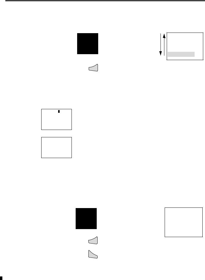
1-12 System Overview
Selecting or Toggling Between Menu Items
Cursor up or down
Select or Toggle
Ok
PROGRAM ...
RUN
PARAMETER
INFO
Highlighted choice flashes
HH:MM 14:23
DD.MM 17.03 YEAR 2004
HH:MM 14:23
DD.MM 17.03 YEAR 2004
Cursor Display
There are two different cursor types: flashing block and flashing cursor.
Full block navigation is shown as a flashing block:
•Move cursor with the left/right arrows
•In circuit diagram also with up/down arrows
Parameter change cursor flashes the selected parameter:
•Change position with left/right arrows
•Change values with up/down arrows
Flashing values/menus are highlighted in grey in this manual.
Setting Values
Change value = up/down arrows
Move cursor between parameters = left/right arrows
HH:MM 14:23
DD.MM 17.03
YEAR 2004
Stores Entries
Ok
Esc |
Retain previous value |
|
Left/right arrow moves the cursor between the day and time digits.
Up/down arrow changes the value of the parameter.
Up arrow = increment Down arrow = decrement
Publication 1760-UM001D-EN-P - September 2005
Chapter 2
Installation
Pico is installed in the following order:
•connect devices together, if necessary
•Mount
•Use surge suppressors
•Wire the inputs
•Wire the outputs
•Connect incoming power
Prevent Electrical Shock
ATTENTION
Follow these guidelines when you handle the controller:
•Remove power before working on any of the wiring to Pico.
•Touch a grounded object to discharge static potential.
•Wear an approved wrist-strap grounding device.
•If available, use a static-safe work station.
Publication 1760-UM001D-EN-P - September 2005

2-2 Installation
European Communities (EC)
Directive Compliance
If this product has the CE mark it is approved for installation within the European Union and EEA regions. It has been designed and tested to meet the following directives.
EMC Directive
This product is tested to meet the Council Directive 89/336/EC Electromagnetic Compatibility (EMC) by applying the following standards, in whole or in part, documented in a technical construction file:
•EN 50081-1 EMC — Generic Emission Standard, Part 1 — Residential, Commercial, and Light Industry
•EN 50082-2 EMC — Generic Immunity Standard, Part 2 — Industrial Environment
This product is intended for use in an industrial environment.
Low Voltage Directive
This product is tested to meet Council Directive 73/23/EEC Low Voltage, by applying the safety requirements of EN 50178 Electric Equipment for Power Installations Equipment Requirements and Tests. For specific information required by EN 50178, see the appropriate sections in this publication, as well as the Allen-Bradley publication Industrial Automation Wiring and Grounding Guidelines For Noise Immunity, publication 1770-4.1.
This equipment is classified as open equipment and must be mounted in an enclosure during operation to provide safety protection.
Publication 1760-UM001D-EN-P - September 2005
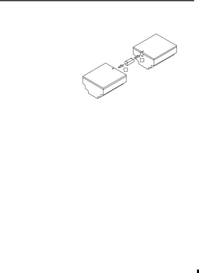
Installation 2-3
Connect the Expansion
Module
Connect the expansion module to the controller using the connector as shown below:
1
2
|
See Expansion Modules on page 1-4 for information on using the |
|
|
modules with your Pico controller. |
|
Mount the Pico Controller |
Install Pico in an enclosure, switch cabinet, or distribution board so |
|
|
that the power feed and terminal connections cannot be touched |
|
|
accidentally during operation. |
|
|
Clip Pico onto a DIN rail or install directly onto a panel using the |
|
|
mounting feet. Pico can be mounted either vertically or horizontally. |
|
|
|
When using a Pico expansion module, connect the |
|
TIP |
|
|
expansion module and Pico controller together |
|
|
|
|
|
|
|
|
|
before mounting. See Connect the Expansion |
|
|
Module. |
Publication 1760-UM001D-EN-P - September 2005
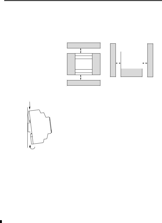
2-4 Installation
Minimum Spacing
Maintain spacing from enclosure walls, wireways, adjacent equipment, etc. Allow 3 cm (1.18 in.) of space on all sides for adequate ventilation, as shown:
3 cm (1.18 in.)
in.) |
|
|
|
|
|
in.) |
|
|
|
|
|
|
|||
(1.18 |
|
|
|
|
|
|
(1.18 |
|
|
|
|
|
|
|
|
cm |
|
|
|
|
|
cm |
|
3 |
|
|
|
|
|
|
3 |
|
|
|
|
|
|||
3 cm (1.18 in.)
DIN Rail Mount
1.Mount your DIN rail. Make sure that the placement of the Pico unit on the DIN rail meets the recommended spacing requirements.
2.Hook the top slot over the DIN rail.
3.While pressing the Pico unit down against the top of the rail, snap the bottom of the unit into position. Ensure DIN latches are in the up (secured) position.
Pico can be mounted vertically on a DIN rail in the same manner.
Publication 1760-UM001D-EN-P - September 2005

Installation 2-5
Install on a Mounting Plate
To install the unit using mounting screws:
1.Snap the mounting feet in place.
2.Drill holes at the mounting feet positions, shown below.
3.Mount the controller.
Click
1760-OW2 |
1760-L12xxx |
1760-L18xxx, 1760-L20xxx and |
Expansion Modules |
For mounting dimensions, see Dimensions on page A-14.
Publication 1760-UM001D-EN-P - September 2005

2-6 Installation
Install the Remote
Processor
The remote processor is used for terminal mode operation of Pico controllers and I/O modules. The remote processor is used with either a Display or Display/Keypad Unit.
Remote Processor Terminal Operation
1760-L12... 1760-L18...
1760-L20...
1760-LDF ...
|
DEL |
ALT |
|
1760-RM |
|
DEL |
ALT |
ESC |
OK |
|
|
|
|
ESC |
OK |
1760-RM-Pico
1760-RM-GFX
1760-GFX
Display Unit
Front View
Flush Mount
Flush Mount the Display and Remote Processor
3 |
|
|
2 |
M = 1.2 – 2 Nm |
|
1 |
10.6 - 17.7 |
lb-in |
2
1.Insert the display unit through the mounting holes on the panel.
2.Attach the fixing rings.
3.Attach the processor unit.
Publication 1760-UM001D-EN-P - September 2005
Loading...