


 Loading...
Multi-ChannelHigh
Speed Counter
(Catalog Number 1746-HSCE2)
User Manual

Important User Information Because of the variety of uses for the products described in this publication, those responsible for the application and use of these
products must satisfy themselves that all necessary steps have been taken to assure that each application and use meets all performance and safety requirements, including any applicable laws, regulations, codes and standards. In no event will Rockwell Automation be responsible or liable for indirect or consequential damage resulting from the use or application of these products.
Any illustrations, charts, sample programs, and layout examples shown in this publication are intended solely for purposes of example. Since there are many variables and requirements associated with any particular installation, Rockwell Automation does not assume responsibility or liability (to include intellectual property liability) for actual use based upon the examples shown in this publication.
Allen-Bradley publication SGI-1.1, Safety Guidelines for the Application, Installation and Maintenance of Solid-State Control
(available from your local Rockwell Automation office), describes some important differences between solid-state equipment and electromechanical devices that should be taken into consideration when applying products such as those described in this publication.
Reproduction of the contents of this copyrighted publication, in whole or part, without written permission of Rockwell Automation, is prohibited.
Throughout this publication, notes may be used to make you aware of safety considerations. The following annotations and their accompanying statements help you to identify a potential hazard, avoid a potential hazard, and recognize the consequences of a potential hazard:
WARNING
!
Identifies information about practices or circumstances that can cause an explosion in a hazardous environment, which may lead to personal injury or death, property damage, or economic loss.
ATTENTION |
Identifies information about practices or |
|
circumstances that can lead to personal injury or |
||
|
!death, property damage, or economic loss.
|
Identifies information that is critical for successful |
|
IMPORTANT |
||
application and understanding of the product. |
||
|
||
|
||
|
|
Allen-Bradley and SLC are trademarks of Rockwell Automation.

|
Table of Contents |
|
|
Preface |
|
|
Who Should Use This Manual . . . . . . . . . . . . . . . . . . . . . . |
P-1 |
|
Purpose of This Manual. . . . . . . . . . . . . . . . . . . . . . . . . . . |
P-1 |
|
Related Documentation . . . . . . . . . . . . . . . . . . . . . . . . |
P-2 |
|
Conventions Used In This Manual . . . . . . . . . . . . . . . . . . . |
P-3 |
|
Your Questions or Comments on the Manual . . . . . . . . . . . |
P-3 |
|
Chapter 1 |
|
Module Overview |
Multi-Channel High-Speed Counter Module Overview . . . . |
1-1 |
|
Counters . . . . . . . . . . . . . . . . . . . . . . . . . . . . . . . . . . . |
1-1 |
|
Inputs . . . . . . . . . . . . . . . . . . . . . . . . . . . . . . . . . . . . . |
1-2 |
|
Outputs . . . . . . . . . . . . . . . . . . . . . . . . . . . . . . . . . . . . |
1-2 |
|
Operation . . . . . . . . . . . . . . . . . . . . . . . . . . . . . . . . . . |
1-2 |
|
Operating Class. . . . . . . . . . . . . . . . . . . . . . . . . . . . . . . . . |
1-4 |
|
Class 1. . . . . . . . . . . . . . . . . . . . . . . . . . . . . . . . . . . . . |
1-4 |
|
Class 4. . . . . . . . . . . . . . . . . . . . . . . . . . . . . . . . . . . . . |
1-4 |
|
Class 1 vs. Class 4 Comparison . . . . . . . . . . . . . . . . . . . |
1-4 |
|
Hardware Features . . . . . . . . . . . . . . . . . . . . . . . . . . . . . . |
1-5 |
|
LEDs . . . . . . . . . . . . . . . . . . . . . . . . . . . . . . . . . . . . . . |
1-5 |
|
Jumpers. . . . . . . . . . . . . . . . . . . . . . . . . . . . . . . . . . . . |
1-6 |
|
Chapter 2 |
|
Module Operation |
Operating Modes . . . . . . . . . . . . . . . . . . . . . . . . . . . . . . . |
2-1 |
|
Input Configurations . . . . . . . . . . . . . . . . . . . . . . . . . . . . . |
2-2 |
|
Pulse/External Direction. . . . . . . . . . . . . . . . . . . . . . . . |
2-2 |
|
Pulse/Internal Direction . . . . . . . . . . . . . . . . . . . . . . . . |
2-3 |
|
Up and Down Pulses . . . . . . . . . . . . . . . . . . . . . . . . . . |
2-3 |
|
X1 Quadrature Encoder . . . . . . . . . . . . . . . . . . . . . . . . |
2-4 |
|
X2 Quadrature Encoder . . . . . . . . . . . . . . . . . . . . . . . . |
2-4 |
|
X4 Quadrature Encoder . . . . . . . . . . . . . . . . . . . . . . . . |
2-4 |
|
Input Frequency . . . . . . . . . . . . . . . . . . . . . . . . . . . . . . . . |
2-5 |
|
Gate/Preset Modes . . . . . . . . . . . . . . . . . . . . . . . . . . . . . . |
2-6 |
|
No Preset . . . . . . . . . . . . . . . . . . . . . . . . . . . . . . . . . . |
2-6 |
|
Soft Preset Only. . . . . . . . . . . . . . . . . . . . . . . . . . . . . . |
2-6 |
|
Store/Continue. . . . . . . . . . . . . . . . . . . . . . . . . . . . . . . |
2-6 |
|
Store/Hold/Resume . . . . . . . . . . . . . . . . . . . . . . . . . . . |
2-7 |
|
Store/Preset/Hold/Resume . . . . . . . . . . . . . . . . . . . . . . |
2-7 |
|
Store/Preset/Start . . . . . . . . . . . . . . . . . . . . . . . . . . . . . |
2-7 |
|
Gate and Preset Limitations . . . . . . . . . . . . . . . . . . . . . |
2-8 |
|
Gate and Preset Considerations . . . . . . . . . . . . . . . . . . |
2-8 |
|
Summary of Available Counter Configurations . . . . . . . . . . |
2-8 |
Publication 1746-UM002B-EN-P - August 2004

Table of Contents ii
|
Counter Types . . . . . . . . . . . . . . . . . . . . . . . . . . . . . . . . . |
2-9 |
|
Linear Counter. . . . . . . . . . . . . . . . . . . . . . . . . . . . . . . |
2-9 |
|
Ring Counter . . . . . . . . . . . . . . . . . . . . . . . . . . . . . . . . |
2-10 |
|
Rate Value . . . . . . . . . . . . . . . . . . . . . . . . . . . . . . . . . . . . |
2-10 |
|
Accuracy . . . . . . . . . . . . . . . . . . . . . . . . . . . . . . . . . . . |
2-11 |
|
Output Control . . . . . . . . . . . . . . . . . . . . . . . . . . . . . . . . . |
2-11 |
|
Range Control. . . . . . . . . . . . . . . . . . . . . . . . . . . . . . . . . . |
2-12 |
|
Count Range . . . . . . . . . . . . . . . . . . . . . . . . . . . . . . . . |
2-12 |
|
Rate Range . . . . . . . . . . . . . . . . . . . . . . . . . . . . . . . . . |
2-14 |
|
Counter Input Data . . . . . . . . . . . . . . . . . . . . . . . . . . . . . . |
2-14 |
|
Class 1 Operation . . . . . . . . . . . . . . . . . . . . . . . . . . . . |
2-15 |
|
Class 4 Operation . . . . . . . . . . . . . . . . . . . . . . . . . . . . |
2-16 |
|
Input Word Bit Values . . . . . . . . . . . . . . . . . . . . . . . . . |
2-17 |
|
Output State Byte. . . . . . . . . . . . . . . . . . . . . . . . . . . . . |
2-18 |
|
Counter Status Bytes . . . . . . . . . . . . . . . . . . . . . . . . . . |
2-18 |
|
Chapter 3 |
|
Installation and Wiring |
Compliance to European Union Directives . . . . . . . . . . . . . |
3-1 |
|
EMC Directive . . . . . . . . . . . . . . . . . . . . . . . . . . . . . . . |
3-1 |
|
Low Voltage Directive . . . . . . . . . . . . . . . . . . . . . . . . . |
3-1 |
|
Prevent Electrostatic Discharge . . . . . . . . . . . . . . . . . . . . . |
3-2 |
|
Setting the Jumpers . . . . . . . . . . . . . . . . . . . . . . . . . . . . . . |
3-2 |
|
Installing the Module. . . . . . . . . . . . . . . . . . . . . . . . . . . . . |
3-3 |
|
Important Wiring Considerations . . . . . . . . . . . . . . . . . . . . |
3-4 |
|
Considerations for Reducing Noise . . . . . . . . . . . . . . . . |
3-5 |
|
Electronic Protection . . . . . . . . . . . . . . . . . . . . . . . . . . . . . |
3-6 |
|
Auto Reset Operation. . . . . . . . . . . . . . . . . . . . . . . . . . |
3-6 |
|
Input and Output Connections . . . . . . . . . . . . . . . . . . . . . |
3-7 |
|
Removing the Terminal Block . . . . . . . . . . . . . . . . . . . |
3-7 |
|
Encoder Wiring. . . . . . . . . . . . . . . . . . . . . . . . . . . . . . . . . |
3-8 |
|
Differential Encoder Wiring . . . . . . . . . . . . . . . . . . . . . |
3-8 |
|
Single-Ended Encoder Wiring (Open Collector). . . . . . . |
3-9 |
|
Single-Ended Wiring (Discrete Devices) . . . . . . . . . . . . |
3-10 |
|
Chapter 4 |
|
Configuration and Programming |
Selecting Operating Class . . . . . . . . . . . . . . . . . . . . . . . . . |
4-1 |
|
Power-up Reset. . . . . . . . . . . . . . . . . . . . . . . . . . . . . . . . . |
4-1 |
|
Module Programming . . . . . . . . . . . . . . . . . . . . . . . . . . . . |
4-1 |
|
Programming Cycle . . . . . . . . . . . . . . . . . . . . . . . . . . . |
4-2 |
|
Data Format. . . . . . . . . . . . . . . . . . . . . . . . . . . . . . . . . |
4-3 |
Publication 1746-UM002B-EN-P - August 2004

Table of Contents |
iii |
|
|
Module Setup Block . . . . . . . . . . . . . . . . . . . . . . . . . . . . . 4-6
Programming Block Identification Bit . . . . . . . . . . . . . . 4-6
TRMT: Transmit Bit . . . . . . . . . . . . . . . . . . . . . . . . . . . 4-6
DEBUG: Debug Mode Selection Bit . . . . . . . . . . . . . . . 4-6
INT: Interrupt Enable . . . . . . . . . . . . . . . . . . . . . . . . . . 4-7
RVF: Rate Value Format . . . . . . . . . . . . . . . . . . . . . . . . 4-7
PRA: Program Range Allocation . . . . . . . . . . . . . . . . . . 4-7
Op Mode: Operating Mode . . . . . . . . . . . . . . . . . . . . . 4-8
Range Allocation Values. . . . . . . . . . . . . . . . . . . . . . . . 4-8
Range Allocation Examples . . . . . . . . . . . . . . . . . . . . . 4-9
Counter Configuration Block . . . . . . . . . . . . . . . . . . . . . . . 4-10
Programming Block Identification Bit . . . . . . . . . . . . . . 4-11
TRMT: Transmit Bit . . . . . . . . . . . . . . . . . . . . . . . . . . . 4-11
DEBUG: Debug Mode Selection Bit . . . . . . . . . . . . . . . 4-11
PGMn: Program Counter Number Bits . . . . . . . . . . . . . 4-12
CType: Counter Type Bit . . . . . . . . . . . . . . . . . . . . . . . 4-12
Input Config: Input Configuration Bits . . . . . . . . . . . . . 4-12
G/P Mode: Gate/Preset Mode Bits . . . . . . . . . . . . . . . . 4-13
Minimum/Maximum Count Value Block. . . . . . . . . . . . . . . 4-13
Programming Block Identification Bit . . . . . . . . . . . . . . 4-14
TRMT: Transmit Bit . . . . . . . . . . . . . . . . . . . . . . . . . . . 4-14
DEBUG: Debug Mode Selection Bit . . . . . . . . . . . . . . . 4-14
AUTO PRESET: Automatic Preset Bit. . . . . . . . . . . . . . . 4-14
CNTR No.: Counter Number Bits . . . . . . . . . . . . . . . . . 4-15
Preset Value . . . . . . . . . . . . . . . . . . . . . . . . . . . . . . . . 4-15
Minimum/Maximum Count Value Words . . . . . . . . . . . 4-15
Counter Type . . . . . . . . . . . . . . . . . . . . . . . . . . . . . . . 4-16
Minimum/Maximum Rate Value Block . . . . . . . . . . . . . . . . 4-16
Programming Block Identification Bit . . . . . . . . . . . . . . 4-17
TRMT: Transmit Bit . . . . . . . . . . . . . . . . . . . . . . . . . . . 4-17
DEBUG: Debug Mode Selection Bit . . . . . . . . . . . . . . . 4-17
CNTR No.: Counter Number Bits . . . . . . . . . . . . . . . . . 4-18
Minimum/Maximum Rate Value Words . . . . . . . . . . . . . 4-18
Operating Class . . . . . . . . . . . . . . . . . . . . . . . . . . . . . . 4-18
Program Ranges Block . . . . . . . . . . . . . . . . . . . . . . . . . . . 4-19
Programming Block Identification Bit . . . . . . . . . . . . . . 4-20
TRMT: Transmit Bit . . . . . . . . . . . . . . . . . . . . . . . . . . . 4-20
DEBUG: Debug Mode Selection Bit . . . . . . . . . . . . . . . 4-20
CNTR No.: Counter Number Bits . . . . . . . . . . . . . . . . . 4-21
Rtype: Range Type. . . . . . . . . . . . . . . . . . . . . . . . . . . . 4-21
Range No.: Range Number Bits. . . . . . . . . . . . . . . . . . . 4-21
Range Start Value, Range Stop Value . . . . . . . . . . . . . . 4-22
Output State: Output State Byte . . . . . . . . . . . . . . . . . . 4-22
Publication 1746-UM002B-EN-P - August 2004

Table of Contents |
iv |
|
|
Start Up, Operation,
Troubleshooting, and Debug Mode
Application Examples
Counter Control Block. . . . . . . . . . . . . . . . . . . . . . . . . . . . 4-23 Transmit Bit. . . . . . . . . . . . . . . . . . . . . . . . . . . . . . . . . 4-24 Programming Block Identification Bit . . . . . . . . . . . . . . 4-24 Control Words . . . . . . . . . . . . . . . . . . . . . . . . . . . . . . . 4-24 ENn: Enable Counter (n) Bit. . . . . . . . . . . . . . . . . . . . . 4-24 SPn: Soft Preset Only (n) Bit . . . . . . . . . . . . . . . . . . . . 4-25 IDn: Internal Direction (n) Bit . . . . . . . . . . . . . . . . . . . 4-25 C/R(n): Count or Rate Value Bit . . . . . . . . . . . . . . . . . . 4-26 P(n): Program Counter (n) Bit . . . . . . . . . . . . . . . . . . . 4-26 Output ON (OR) Mask . . . . . . . . . . . . . . . . . . . . . . . . . 4-26 Output Enable Mask . . . . . . . . . . . . . . . . . . . . . . . . . . 4-26 Enable Range. . . . . . . . . . . . . . . . . . . . . . . . . . . . . . . . 4-27 Determining Actual Output State . . . . . . . . . . . . . . . . . 4-27
Programming Block Default Values . . . . . . . . . . . . . . . . . . 4-28 Class 1. . . . . . . . . . . . . . . . . . . . . . . . . . . . . . . . . . . . . 4-28 Class 4. . . . . . . . . . . . . . . . . . . . . . . . . . . . . . . . . . . . . 4-30
Chapter 5
Start Up . . . . . . . . . . . . . . . . . . . . . . . . . . . . . . . . . . . . . . 5-1
Normal Operation . . . . . . . . . . . . . . . . . . . . . . . . . . . . . . . 5-1
Troubleshooting . . . . . . . . . . . . . . . . . . . . . . . . . . . . . . . . 5-2
Module Diagnostic Errors . . . . . . . . . . . . . . . . . . . . . . . 5-2
Module Programming Errors. . . . . . . . . . . . . . . . . . . . . 5-3
Application Errors . . . . . . . . . . . . . . . . . . . . . . . . . . . . 5-4
Debug Mode Operation. . . . . . . . . . . . . . . . . . . . . . . . . . . 5-7
Activating Debug Mode . . . . . . . . . . . . . . . . . . . . . . . . 5-7
Chapter 6
Example 1 - Direct Addressing. . . . . . . . . . . . . . . . . . . . . . 6-2 Data Table for N10 File (hexidecimal). . . . . . . . . . . . . . 6-7 Data Table for N11 File (decimal) . . . . . . . . . . . . . . . . . 6-7 Example 2 - Indirect Addressing . . . . . . . . . . . . . . . . . . . . 6-7 Data Table for N10 File (hexidecimal). . . . . . . . . . . . . . 6-10 Data Table for N11 File (decimal) . . . . . . . . . . . . . . . . . 6-10 Example 3 - Block Transfers . . . . . . . . . . . . . . . . . . . . . . . 6-10 Data Table for N10 File (hexidecimal). . . . . . . . . . . . . . 6-14 Data Table for N11 File (decimal) . . . . . . . . . . . . . . . . . 6-14 Example 4 - Using Soft Presets. . . . . . . . . . . . . . . . . . . . . . 6-14 Ladder File 9 - HSCE2 Initialization Routine . . . . . . . . . 6-17 Data Table for N10 File (hexidecimal). . . . . . . . . . . . . . 6-18 Data Table for N11 File (decimal) . . . . . . . . . . . . . . . . . 6-18 Example 5 - Change Presets Dynamically . . . . . . . . . . . . . . 6-18 Data Table for N10 File (hexidecimal). . . . . . . . . . . . . . 6-22 Data Table for N11 File (decimal) . . . . . . . . . . . . . . . . . 6-22
Publication 1746-UM002B-EN-P - August 2004

|
|
Table of Contents v |
|
|
|
|
Example 6 - Retentive Counters . . . . . . . . . . . . . |
. . . . . . . . 6-23 |
|
Data Table for N10 File (hexidecimal). . . . . . |
. . . . . . . . 6-25 |
|
Data Table for N11 File (decimal) . . . . . . . . . . |
. . . . . . . 6-25 |
|
Appendix A |
|
Specifications |
General . . . . . . . . . . . . . . . . . . . . . . . . . . . . . . . |
. . . . . . . A-1 |
|
Inputs A, B, and Z . . . . . . . . . . . . . . . . . . . . . . . |
. . . . . . . A-2 |
|
Outputs (sourcing) . . . . . . . . . . . . . . . . . . . . . . . |
. . . . . . . A-2 |
|
On-State Current Derating . . . . . . . . . . . . . . . |
. . . . . . . A-3 |
|
Throughput and Timing . . . . . . . . . . . . . . . . . . . |
. . . . . . . A-3 |
Appendix B
Connecting a Differential Encoder
Appendix C
Module Programming Quick
Reference
Appendix D
Frequently Asked Questions
Appendix E
Comparing 1746-HSCE2 to 1746-HSCE
Glossary
Index
Publication 1746-UM002B-EN-P - August 2004

Table of Contents |
vi |
|
|
Publication 1746-UM002B-EN-P - August 2004

Summary of Changes
New Information
The information below summarizes the changes to this manual since the last printing.
To help you find new information and updated information in this release of the manual, we have included change bars as shown to the right of this paragraph.
The table below lists sections that include new information.
For this new information |
See page(s) |
|
|
Note on limitations of rate value calculation at input frequencies |
2-11 |
below 60 Hz. |
|
|
|
Clarified operation of Module Fault (MFLT) bit |
2-17 |
|
|
Updated resistor information in single-ended wiring diagrams |
3-9 and 3-10 |
|
|
Clarified programming cycle |
4-2 |
|
|
Modifications to the COP instruction example for reading and writing |
4-4 |
floating point data |
|
|
|
Corrected bit identification in Output State Byte |
4-22 |
|
|
Example showing how to activate debug mode |
5-10 |
|
|
Corrected bit identification table for Program Ranges Block |
C-2 |
|
|
Publication 1746-UM002B-EN-P - August 2004

2 Summary of Changes
Publication 1746-UM002B-EN-P - August 2004
Preface
Who Should Use This
Manual
Purpose of This Manual
Read this preface to familiarize yourself with the rest of the manual. This preface covers the following topics:
•who should use this manual
•how to use this manual
•related publications
•conventions used in this manual
•Rockwell Automation support
Use this manual if you are responsible for designing, installing, programming, or troubleshooting control systems that use Allen-Bradley small logic controllers.
You should have a basic understanding of SLC 500™ products. You should understand programmable controllers and be able to interpret the ladder logic instructions required to control your application. If you do not, contact your local Rockwell Automation representative for information on available training courses before using this product.
As much as possible, we organized this manual to explain, in a task-by-task manner, how to install, configure, program, operate and troubleshoot an SLC 500-based system using the 1746-HSCE2 module.
Publication 1746-UM002B-EN-P - August 2004

2 Preface
Related Documentation
The table below provides a listing of publications that contain important information about SLC™ products.
|
|
For |
Read this document |
Document number |
|
|
|
|
|
|
|
A reference manual containing status file data, instruction |
SLC 500™ Instruction Set Reference |
1747-RM001 |
|
|
|||
|
|
set, and troubleshooting information |
Manual |
|
|
|
|
|
|
|
|
A description of how to install and use your Modular |
SLC 500™ Modular Hardware Style |
1747-UM011 |
|
|
|||
|
|
SLC 500 programmable controller |
User Manual |
|
|
|
|
|
|
|
|
An overview of the SLC 500™ family of products |
SLC 500 Systems Selection Guide |
1747-SG001 |
|
|
|||
|
|
|
|
|
|
|
In-depth information on grounding and wiring |
Allen-Bradley Programmable Controller |
1770-4.1 |
|
|
Allen-Bradley programmable controllers |
Grounding and Wiring Guidelines |
|
|
|
|
|
|
|
|
A description of important differences between solid-state |
Application Considerations for |
SGI-1.1 |
|
|
programmable controller products and hard-wired |
Solid-State Controls |
|
|
|
electromechanical devices |
|
|
|
|
|
|
|
|
|
An article on wire sizes and types for grounding electrical |
National Electrical Code |
Published by the National Fire |
|
|
equipment |
|
Protection Association of Boston, |
|
|
|
|
MA |
|
|
|
|
|
|
|
A glossary of industrial automation terms and |
Allen-Bradley Industrial Automation |
AG-7.1 |
|
|
abbreviations |
Glossary |
|
|
|
|
|
|
If you would like a manual, you can:
•view and download a free electronic version from the internet at www.rockwellautomation.com/literature
•purchase a printed manual by contacting your local Allen-Bradley distributor or Rockwell Automation sales office
Publication 1746-UM002B-EN-P - August 2004

Preface 3
Conventions Used In This
Manual
Your Questions or Comments on the Manual
The following conventions are used throughout this manual:
•Bulleted lists (like this one) provide information, not procedural steps.
•Numbered lists provide sequential steps or hierarchical information.
•Italic type is used for emphasis.
•Text in this font indicates words or phrases you should type.
If you find a problem with this manual, please notify us. If you have any suggestions for how this manual could be made more useful to you, please contact us at the address below:
Rockwell Automation
Automation Control and Information Group
Technical Communication, Dept. A602V
P.O. Box 2086
Milwaukee, WI 53201-2086
Publication 1746-UM002B-EN-P - August 2004

4 Preface
Publication 1746-UM002B-EN-P - August 2004

Chapter 1
Module Overview
Multi-Channel High-Speed
Counter Module Overview
This chapter contains the following:
•multi-channel high-speed counter module overview
•operating class
•hardware features
The 1746-HSCE2 is an intelligent counter module with its own microprocessor and I/O that is capable of reacting to high-speed input signals without the intervention of the SLC processor. The module is compatible with the SLC 500 family and can be used in a remote chassis with the SLC Remote I/O Adapter Module (1747-ASB).
Counters
The module is able to count in either direction. A maximum of four pulse counters are available (or 2 quadrature counters). Each counter can count to +/- 8,388,607 as a ring or linear counter. In addition to providing a count value, the module provides a rate value up to +/-1 MHz, dependent on the type of input. The rate value is the input frequency (in Hertz) to the counter. When the count value is increasing, the rate value is positive. When the count value is decreasing, the rate value is negative.
Counters can also be preset to any value between the minimum and maximum values. The conditions that preset the count value and generate capture values are configured by the gate/preset modes. The four counters can have different gate/preset modes.
Publication 1746-UM002B-EN-P - August 2004

1-2 Module Overview
Inputs
The module features six high-speed differential inputs labeled ±A1, ±B1, ±Z1, ±A2, ±B2, and ±Z2. It supports quadrature encoders with ABZ inputs and/or up to six discrete switches. In addition, x1, x2, and x4 counting configurations are provided to fully use the capabilities of high resolution quadrature encoders. The inputs can be wired for single-ended or differential use. Inputs are opto-isolated from the backplane.
Outputs
Eight outputs are available, four real (dc sourcing) and four virtual bits. The virtual outputs are available to the processor only. The real outputs are protected from overloads by a self-resetting fuse. The outputs can be controlled by any or all of the counters and/or directly controlled by the user’s program.
Up to 16 dynamically configurable ranges are available, using rates or counts to control outputs. The ranges, programmed with range start and range stop values, can overlap. If the count or rate is within more than one range, the output patterns of those ranges are combined (logically ORed) to determine the actual status of the output. When an output is enabled by more than one counter and/or with the user program, its output state is determined by logically ORing the programmed setpoints of all those counters and the user program.
Operation
Module operation is controlled by user-programmed settings in the following six module programming blocks.
•Module Setup Block
•Counter Configuration Block
•Minimum/Maximum Count Value Block
•Minimum/Maximum Rate Value Block
•Program Ranges Block
•Counter Control Block
Publication 1746-UM002B-EN-P - August 2004

Module Overview |
1-3 |
|
|
Most programming parameters, except those in the Module Setup and Counter Configuration blocks, are dynamic and can be changed without halting counter operation. The table below lists the static and dynamic parameters by programming block.
Programming Block |
Parameter |
Type(1) |
|
|
Operating Mode |
|
|
|
|
|
|
Module Setup |
Range Allocation |
Static |
|
|
|||
Interrupt Enable |
|||
|
|
||
|
|
|
|
|
Rate Value Format |
|
|
|
|
|
|
|
Counter Type |
|
|
Counter Configuration |
|
Static(2) |
|
Input Configuration |
|||
|
Gate/Preset Mode |
|
|
|
|
|
|
|
Minimum Count |
Static(2) |
|
Min./Max. Count Value |
Maximum Count |
Static(2) |
|
|
Preset Value |
Dynamic(3) |
|
Min./Max. Rate Value |
Minimum Rate |
Dynamic |
|
|
|
||
|
Maximum Rate |
||
|
|
||
|
|
|
|
|
Counter Number |
|
|
|
|
|
|
|
Range Type |
|
|
|
|
|
|
Program Range |
Range Number |
Dynamic |
|
|
|||
Start Value |
|||
|
|
||
|
|
|
|
|
Stop Value |
|
|
|
|
|
|
|
Output Image |
|
|
|
|
|
|
|
Enabled |
|
|
|
|
|
|
|
Soft Preset Only |
|
|
|
|
|
|
|
Internal Direction |
|
|
Counter Control |
|
Dynamic |
|
Output ON Mask |
|||
|
|
|
|
|
Output OFF Mask |
|
|
|
|
|
|
|
Count or Rate Value |
|
|
|
|
|
|
|
Range Enable Mask |
|
|
|
|
|
(1)STATIC = the associated counter must be disabled to set this parameter.
DYNAMIC = this parameter may be changed while the associated counter is running.
(2)Only the selected counter must be disabled.
(3)Under specific conditions, this parameter is dynamic. See page 4-15 for more information.
Publication 1746-UM002B-EN-P - August 2004

1-4 Module Overview
Operating Class
Module operation differs slightly based on the operating class. The operating class is selected via the module ID code.
Class 1
Class 1 operation is compatible with all SLC 500 processors. In Class 1 operation, the module uses 8 input and 8 output words and has an associated ID code of 3511. A maximum of four 16-bit counters are available in this operating class.
Class 4
Class 4 operation is compatible with SLC 5/03 and above systems. In Class 4 operation, the module uses 23 input and 8 output words and has an associated ID code of 15912. A maximum of four 24-bit counters are available in this class.
Class 1 vs. Class 4 Comparison
Class |
Class 1 |
Class 4 |
|
|
|
Counters |
16-bit (±32,767) |
24-bit (±8,388,607) |
|
|
|
Input Words |
8 with limited information. |
23 with all information. |
|
|
|
Backplane Interrupts |
Not permitted. |
Permitted. |
|
|
|
Use in RIO Chassis |
Permitted. |
Not permitted. |
|
|
|
Use in ControlNet Chassis |
Not permitted. |
Permitted. |
|
|
|
Module ID Code |
3511 |
15912 |
|
|
|
Publication 1746-UM002B-EN-P - August 2004
Module Overview |
1-5 |
|
|
Hardware Features
The module’s hardware features are illustrated below. Refer to Chapter 3 for detailed information on installation and wiring.
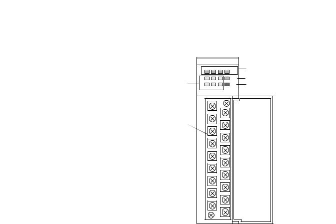
Figure 1.1 Hardware Features
|
COUNTER |
|||
|
OUTPUT STATUS |
|||
|
0 |
1 |
2 |
3 |
|
A1 |
B1 |
Z1 |
RUN |
Input Status LEDs |
A2 |
B2 |
Z2 |
FLT |
|
INPUT STATUS |
|
||
|
HSCE2 |
|
|
|
Input and Output |
|
|
|
|
Terminals |
|
|
|
|
Output Status LEDs
Running Status LED
Fault Status LED
LEDs
The front panel has a total of twelve indicator LEDs, as shown in Figure 1.1 on page 1-5.
LED |
Color |
Indicates |
|
|
|
0 OUT |
Green |
ON/OFF status of real output |
|
|
|
1 OUT |
Green |
ON/OFF status of real output |
|
|
|
2 OUT |
Green |
ON/OFF status of real output |
|
|
|
3 OUT |
Green |
ON/OFF status of real output |
|
|
|
RUN |
Green |
Running status of the module |
|
|
|
FLT |
Red |
Steady on: Module fault |
|
|
Flashing: Output overcurrent |
|
|
|
A1 |
Yellow |
ON/OFF status of input A1 |
|
|
|
A2 |
Yellow |
ON/OFF status of input A2 |
|
|
|
B1 |
Yellow |
ON/OFF status of input B1 |
|
|
|
B2 |
Yellow |
ON/OFF status of input B2 |
|
|
|
Z1 |
Yellow |
ON/OFF status of input Z1 |
|
|
|
Z2 |
Yellow |
ON/OFF status of input Z2 |
|
|
|
Publication 1746-UM002B-EN-P - August 2004

1-6 Module Overview
Jumpers
Six jumpers select the input voltages for the six inputs A1, B1, Z1, A2, B2, and Z2. The module accepts input voltages of 5V dc, 12V dc, or 24V dc. See Chapter 3 for jumper locations and settings.
Publication 1746-UM002B-EN-P - August 2004
Chapter 2
Module Operation
Operating Modes
The chapter contains information about:
•operating modes
•input configurations
•gate/preset modes
•counter types
•rate value
•outputs
•range types
The module’s operating mode determines the number of available counters and which inputs are attached to them. The three operating modes and their input assignments are summarized in Figure 2.1.
Figure 2.1 Operating Mode Input Assignments
A1 |
Counter 1 |
Counter 3 |
A1 |
Counter 1 |
Counter 3 |
||
B1 |
B1 |
||||||
|
|
|
|
B2 |
|||
Z1 |
|
|
Z1 |
|
|
|
|
A2 |
Counter 2 |
Counter 4 |
A2 |
Counter 2 |
Counter 4 |
||
B2 |
|
||||||
|
|
|
|
|
|
||
Z2 |
|
|
Z2 |
|
|
|
|
|
Operating Mode 1 |
|
|
Operating Mode 2 |
|||
|
|
A1 |
Counter 3 |
|
|
||
|
|
Counter 1 |
B2 |
|
|||
|
|
|
|
|
|
||
|
|
Z1 |
|
|
|
|
|
|
|
A2 |
|
|
|
|
|
|
|
Counter 2 |
Counter 4 |
B1 |
|
||
|
|
|
|
|
|
||
Z2
Operating Mode 3
Publication 1746-UM002B-EN-P - August 2004
2-2 Module Operation
Input Configurations
Input configurations determine how the A and B inputs cause the counter to increment or decrement. The six available configurations are:
•Pulse/External Direction
•Pulse/Internal Direction
•Up and Down Pulses
•X1 Quadrature Encoder
•X2 Quadrature Encoder
•X4 Quadrature Encoder
See the Summary of Available Counter Configurations on page 2-8 for the input configurations available for the counters, based on operating mode.
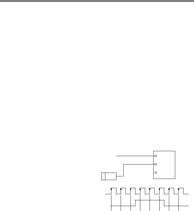
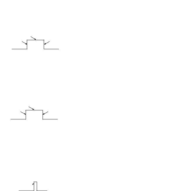
Pulse/External Direction
With this configuration, the B input controls the direction of the counter, as shown below. If the B input is low (0), the counter increments on the rising edges of input A. If the input B is high (1), the counter decrements on the rising edges of input A.
Figure 2.2 Pulse/External Direction Configuration
|
|
|
|
|
Count Pulse |
Input A |
|
|
|
|
|
||
|
|
|
|
|
Direction Control |
|
|
|
|
|
|
|
|
|
|
|
|
|
|
|
|
|
|
Encoder or Sensor |
Input B |
||
|
|
|
|
|
|
Input Z |
|
|
Sensor or Switch |
|
|
||
Count Pulse
Direction Control
High = Decrement
Low = Increment
Count |
1 |
2 |
3 |
2 |
1 |
0 |
1 |
2 |
Publication 1746-UM002B-EN-P - August 2004
Module Operation |
2-3 |
|
|
Pulse/Internal Direction
When the Pulse/Internal Direction configuration is selected, a bit written from the backplane determines the direction of the counter. The counter increments on the rising edge of the input if the bit is low
(0) and decrements on the rising edge of the input if the bit is high
(1).
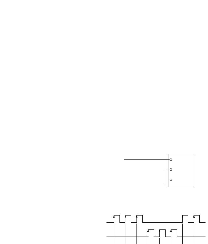
Up and Down Pulses
In this configuration, the counter increments on the rising edge of pulses applied to input A and decrements on the rising edge of pulses applied to input B.
TIP |
When both inputs transition simultaneously or near |
|
simultaneously, the net result is no change to the |
||
|
||
|
||
|
count value. Therefore, simultaneous (or near |
|
|
simultaneous) pulses are ignored and no change in |
|
|
the count value is reported. |
Figure 2.3 Up and Down Pulse Configuration
|
|
|
|
|
|
Increment Pulse |
Input A |
|
|
|
|
|
|
||
|
|
|
|
|
|
||
|
|
|
|
|
|
|
|
|
|
|
|
|
|
(count up) |
|
|
|
Incrementing Encoder |
Input B |
||||
|
|
|
|||||
|
|
|
|
or Sensor |
|
|
|
|
|
|
|
|
|
|
Input Z |
|
|
|
|
|
|
|
|
|
|
|
|
|
|
|
|
|
|
|
|
|
|
|
|
|
|
|
|
|
|
Decrement Pulse |
Module |
|
|
|
|
|
|
(count down) |
|
|
|
|
|
|
|
|
|
Decrementing Encoder or |
|
||||||
|
|
||||||
|
|
|
|
Sensor |
|
|
|
Increment Pulse
(Input A)
Decrement Pulse
(Input B)
Count |
1 |
2 |
3 |
2 |
1 |
0 |
1 |
2 |
Publication 1746-UM002B-EN-P - August 2004

2-4 Module Operation
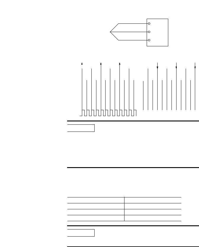
X1 Quadrature Encoder
When a quadrature encoder is attached to inputs A and B, the count direction is determined by the phase angle between inputs A and B. If A leads B, the counter increments. If B leads A, the counter decrements. The counter changes value only on one edge of input A as shown in Figure 2.4 on page 2-5.
TIP |
If B is low, the count increments on the rising edge |
|
of input A and decrements on the falling edge of |
||
|
||
|
||
|
input A. If B is high, all transitions on input A are |
|
|
ignored. |
X2 Quadrature Encoder
Like the X1 Quadrature Encoder, the count direction is determined by the phase angle between inputs A and B. If A leads B, the counter increments. If B leads A, the counter decrements. However, the counter changes value on the rising and falling edges of input A, as shown in Figure 2.4 on page 2-5.
X4 Quadrature Encoder
Operation is similar to the X2 Quadrature Encoder configuration, except the counter changes value on the rising and falling edges of inputs A and B as shown in Figure 2.4.
Publication 1746-UM002B-EN-P - August 2004
Module Operation |
2-5 |
|
|
Input Frequency
Figure 2.4 Quadrature Encoder Configurations
|
|
|
|
|
|
|
|
|
|
|
|
|
|
|
|
|
|
|
|
|
|
|
A |
|
|
|
Input A |
|
|
|
|
|
|
|
|
|
|
|
|
|
|
|
|
|||||||
|
|
|
|
|
|
|
|
|
|
|
|
|
|
|
|
|
|
|
|
|
|
|
|
|
|
|
|
|
|
|
|
|
|
|
|
|
|
|
|
|
|
|
|
|
|
|||||
|
|
|
|
|
|
|
|
|
|
|
|
|
|
|
|
|
|
|
|
|
|
|
B |
|
|
|
Input B |
|
|
|
|
|
|
|
|
|
|
|
|
|
|
|
|
|||||||
|
|
|
|
|
|
|
|
|
|
|
|
|
|
|
|
|
|
|
|
|
|
|
|
|
|
|
|
|
|
|
|
|
|
|
|
|
|
|
|
|
|
|||||||||
|
|
|
|
|
|
|
|
|
|
|
|
|
|
|
|
|
|
|
|
|
|
|
|
|
|
|
|
|
|
|
|
|
|
|
|
|
|
|
|
|
|
|||||||||
|
|
|
|
|
|
|
|
|
|
|
|
|
|
|
|
|
|
|
|
|
|
|
Z |
|
|
|
|
|
|
|
|
|
|
|
|
|
|
|
|
|
|
|
|
|
|
|
|
|||
|
|
|
|
|
|
|
|
|
|
|
|
|
|
|
|
|
|
|
|
|
|
|
|
|
|
|
|
|
|
|
|
|
|
|
|
|
|
|
|
|
|
|
|
|
|
|
||||
|
|
|
|
|
|
|
|
|
|
|
Quadrature |
|
|
|
|
|
|
|
|
|
Input Z |
|
|
|
|
|
|
|
|
|
|
|
|
|
|
|
|
|||||||||||||
|
|
|
|
|
|
|
|
|
|
|
|
|
|
|
|
|
|
|
|
|
|
|
|
|
|
|
|
|
|
|
|
|
|
|
|
|
|
|
|
|||||||||||
|
|
|
|
|
|
|
|
|
|
|
|
Encoder |
|
|
|
|
|
|
|
|
|
|
|
|
|
|
|
|
|
|
|
|
|
|
|
|
|
|
|
|
|
|
|
|
|
|
||||
|
|
|
|
|
|
|
|
|
|
|
Forward Rotation |
|
|
|
|
|
|
|
|
|
|
|
|
|
|
|
Reverse Rotation |
|
|
|
|
|
|
|||||||||||||||||
|
A |
|
|
|
|
|
|
|
|
|
|
|
|
|
|
|
|
|
|
|
|
|
|
|
|
|
|
|
|
|
|
|
|
|
|
|
|
|
|
|
|
|
|
|
|
|
|
|||
|
|
|
|
|
|
|
|
|
|
|
|
|
|
|
|
|
|
|
|
|
|
|
|
|
|
|
|
|
|
|
|
|
|
|
|
|
|
|
|
|
|
|
|
|
|
|
|
|||
|
|
|
|
|
|
|
|
|
|
|
|
|
|
|
|
|
|
|
|
|
|
|
|
|
|
|
|
|
|
|
|
|
|
|
|
|
|
|
|
|
|
|
|
|
|
|||||
|
B |
|
|
|
|
|
|
|
|
|
|
|
|
|
|
|
|
|
|
|
|
|
|
|
|
|
|
|
|
|
|
|
|
|
|
|
|
|
|
|
|
|
|
|
|
|
|
|||
|
|
|
|
|
|
|
|
|
|
|
|
|
|
|
|
|
|
|
|
|
|
|
|
|
|
|
|
|
|
|
|
|
|
|
|
|
|
|
|
|
|
|
|
|
|
|
||||
|
|
|
|
|
|
|
|
|
|
|
|
|
|
|
|
|
|
|
|
|
|
|
|
|
|
|
|
|
|
|
|
|
|
|
|
|
|
|
|
|
|
|
|
|
|
|||||
1 |
|
|
|
|
|
|
|
2 |
|
|
|
|
|
3 |
|
|
|
|
|
|
2 |
|
|
|
|
|
|
|
1 |
|
|
|
|
|
|
0 |
|
|
|
|
||||||||||
X1 Count |
|
|
|
|
|
|
|
|
|
|
|
|
|
|
|
|
|
|
|
|
|
|
|
|
|
|
|
|
|
|
|
|
|
|
|
|
|
|
|
|
|
|
|
|
|
|
|
|||
|
|
|
|
|
|
|
|
|
|
|
|
|
|
|
|
|
|
|
|
|
|
|
|
|
|
|
|
|
|
|
|
|
|
|
|
|
|
|
|
|
|
|
|
|
|
|
||||
|
|
|
|
|
|
|
|
|
|
|
|
|
|
|
|
|
|
|
|
|
|
|
|
|
|
|
|
|
|
|
|
|
|
|
|
|
|
|
|
|
|
|
|
|
|
|||||
1 |
|
|
|
|
2 |
|
|
3 |
|
|
4 |
|
|
5 |
|
|
6 |
|
|
|
5 |
|
|
4 |
|
|
|
3 |
|
|
2 |
|
|
1 |
|
|
|
0 |
||||||||||||
X2 Count |
|
|
|
|
|
|
|
|
|
|
|
|
|
|
|
|
|
|
|
|
|
|
|
|
|
|
|
|
|
|
|
|
|
|
|
|
|
|
|
|
|
|
|
|
|
|
|
|||
|
|
|
|
|
|
|
|
|
|
|
|
|
|
|
|
|
|
|
|
|
|
|
|
|
|
|
|
|
|
|
|
|
|
|
|
|
|
|
|
|
|
|
|
|
|
|
||||
|
|
|
|
|
|
|
|
|
|
|
|
|
|
|
|
|
|
|
|
|
|
|
|
|
|
|
|
|
|
|
|
|
|
|
|
|
|
|
|
|
|
|
|
|
|
|||||
1 |
2 |
3 |
4 |
5 |
6 |
7 |
8 |
9 |
10 |
11 12 |
11 10 |
9 |
8 |
|
7 |
6 |
5 |
4 |
3 |
2 |
|
1 |
|
0 |
||||||||||||||||||||||||||
X4 Count |
|
|
|
|
|
|
|
|
|
|
|
|
|
|
|
|
|
|
|
|
|
|
|
|
|
|
|
|
|
|
|
|
|
|
|
|
|
|
|
|
|
|
|
|
|
|||||
|
|
|
|
|
|
|
|
|
|
|
|
|
|
|
|
|
|
|
|
|
|
|
|
|
|
|
|
|
|
|
|
|
|
|
|
|
|
|
|
|
|
|
|
|
||||||
|
|
|
|
|
|
|
The input configuration is limited by the operating |
|
||||||||||||||||||||||||||||||||||||||||||
|
|
|
|
|
|
|
|
|
|
|
|
|
|
|||||||||||||||||||||||||||||||||||||
|
IMPORTANT |
|
|
|
||||||||||||||||||||||||||||||||||||||||||||||
|
|
|
mode. In mode 1, Counters 1 and 2 can be assigned |
|||||||||||||||||||||||||||||||||||||||||||||||
|
|
|
|
|
|
|
|
|
|
|
|
|
||||||||||||||||||||||||||||||||||||||
|
|
|
|
|
|
|
|
|
|
|
|
|
||||||||||||||||||||||||||||||||||||||
|
|
|
|
|
|
|
|
|
|
|
|
|
any input configuration. In mode 2, Counter 1 can |
|
||||||||||||||||||||||||||||||||||||
|
|
|
|
|
|
|
|
|
|
|
|
|
be assigned any configuration, but Counters 2 and 3 |
|||||||||||||||||||||||||||||||||||||
|
|
|
|
|
|
|
|
|
|
|
|
|
are configured as pulse/internal direction. In mode |
|||||||||||||||||||||||||||||||||||||
|
|
|
|
|
|
|
|
|
|
|
|
|
3, all counters have the pulse/internal direction |
|
|
|
||||||||||||||||||||||||||||||||||
|
|
|
|
|
|
|
|
|
|
|
|
|
configuration. See the Summary of Available Counter |
|||||||||||||||||||||||||||||||||||||
|
|
|
|
|
|
|
|
|
|
|
|
|
Configurations on page 2-8. |
|
|
|
|
|
|
|
|
|
|
|
|
|
|
|
|
|
|
|
||||||||||||||||||
Input frequency is determined by the input configuration as shown in the table below.
Input Configuration |
Input Frequency |
||
X4 Quadrature Encoder |
250 kHz |
||
X2 Quadrature Encoder |
500 kHz |
||
All Other Configurations |
1 MHz |
||
|
The minimum high and low times for the pulse train |
||
IMPORTANT |
|||
are 475 ns. Therefore, the input pulse train must fall |
|||
|
|||
|
|||
|
between a 47.5 to 52.5 percent duty cycle at 1 MHz. |
||
Publication 1746-UM002B-EN-P - August 2004

2-6 Module Operation
Gate/Preset Modes
store, continue counting
A counter’s gate/preset mode determines what, if any, gating is applied to the counter and what, if any, conditions will preset the counter to the preset value. The Z inputs are the only inputs used for gating or presetting. The six gate/preset modes are described below.
No Preset
The counter is not preset under any conditions. The Z inputs are not used.
Soft Preset Only
The counter is preset when the matching preset bit in the SLC 500 output image table experiences a positive transition, but not in response to the Z input.
TIP |
The soft preset bit operates in all the gate/preset |
|
modes except No Preset. |
||
|
||
|
Store/Continue
The count value is captured when the module detects an inactive-to-active transition on the Z input of the counter. This stored value is made available to the backplane. A stored status bit in the input image table is set to signal the processor that a new value is available. This bit is active until the capture value is read by the processor. Therefore, it is on for a maximum of 10 ms in Class 1, and a maximum of one scan or 10 ms, whichever is shorter, in Class 4. If a second capture event occurs before the first is read, the first value is lost. The count and rate values are not affected by a store event.
Publication 1746-UM002B-EN-P - August 2004
Module Operation |
2-7 |
|
|
counter has stopped counting |
resume |
|
|
stop count |
counting |
|
|
store count |
|
Store/Hold/Resume
The count value, captured when the module detects a positive transition on the Z input, is made available to the backplane. A stored status bit is set in the input image table to signal the processor that a new value is available. This bit is active until the capture value is read by the processor. Therefore, it is on for a maximum of 10 ms in Class 1, and a maximum of one scan or 10 ms, whichever is shorter, in Class 4. The count value is held as long as the Z input is active. Because the count value is not changing, the rate value is equal to zero while the counter is held.
counter has |
start |
stopped counting |
counting |
stop count, |
from preset |
|
|
store count, |
|
Store/Preset/Hold/Resume
The counter is set to its programmed preset value when the module detects a positive transition on the Z input of the counter. The capture value is made available to the backplane. A stored status bit is set in the input image table to signal the processor that a new value is available. This bit is active until the capture value is read by the processor. Therefore, it is on for a maximum of 10 ms in Class 1, and a maximum of one scan or 10 ms, whichever is shorter, in Class 4. The preset counter value is held as long as the Z input remains active. Because the count value is not changing, the rate value equals zero while the preset value is held.
store count, preset, start counting 
Store/Preset/Start
The counter is set to its programmed preset value when the module detects a positive transition on the Z input of the counter. The capture value is made available to the backplane. A stored status bit is set in the input image table to signal the processor that a new value is available.This bit is active until the capture value is read by the processor. Therefore, it is on for a maximum of 10 ms in Class 1, and a maximum of one scan or 10 ms, whichever is shorter, in Class 4.
Publication 1746-UM002B-EN-P - August 2004

2-8 Module Operation
Summary of Available
Counter Configurations
Gate and Preset Limitations
Because only the Z inputs are used for external gating and presetting, the only gate/preset modes available for Counters 3 and 4 are No Preset and Soft Preset Only. All six modes are always available for Counters 1 and 2.
|
In Class 1, Operating Mode 2, Counter 2 does not |
|
IMPORTANT |
||
have a capture value available. In Class 1, Operating |
||
|
||
|
||
|
Mode 3, no capture values are available. |
|
|
|
Gate and Preset Considerations
Z-pulse Preset Operation
In applications where the Z pulse of the encoder is being used to preset the position, and where the Z pulse of the encoder is aligned with either the A or B pulses, the capture or count value may be affected by ± 1 count. If the Z pulse is edge aligned with the A pulse, preset operations may not be performed accurately in any of the quadrature modes. If the Z pulse is edge aligned with the B pulse, preset operation may not be performed accurately in the X4 quadrature mode only. A small capacitor (for example, 0.01 µF) across the Z inputs will dis-align these inputs and should correct this condition.
The table below summarizes the input configurations and gate/preset modes available for all counters, based on operating mode.
Operating |
Counter |
Input Configuration |
Gate/Preset Mode |
Mode |
|
|
|
|
|
|
|
1 |
1 |
All |
All |
|
|
|
|
|
2 |
All |
All |
|
|
|
|
2 |
1 |
All |
All |
|
|
|
|
|
2 |
Pulse/Internal Direction |
All |
|
|
|
|
|
3 |
Pulse/Internal Direction |
No Preset or Soft Preset Only |
|
|
|
|
3 |
1 |
Pulse/Internal Direction |
All |
|
|
|
|
|
2 |
Pulse/Internal Direction |
All |
|
|
|
|
|
3 |
Pulse/Internal Direction |
No Preset or Soft Preset Only |
|
|
|
|
|
4 |
Pulse/Internal Direction |
No Preset or Soft Preset Only |
|
|
|
|
Publication 1746-UM002B-EN-P - August 2004
Module Operation |
2-9 |
|
|
Counter Types
Each counter can be programmed to operate as a linear or ring counter. Both types are described below.
Linear Counter
The figure below demonstrates linear counter operation. In linear operation, the count value must remain within the programmed minimum/maximum values. If the count value goes above or below these values, the counter stops counting, and an overflow/underflow bit is set. In the overflow or underflow condition, the rate value continues to be updated and valid.
The number of pulses accumulated in an overflow/underflow state are ignored. The counter begins counting again when pulses are applied in the proper direction. For example, if you exceed the maximum by 1,000 counts, you do not need to apply 1,000 counts in the opposite direction before the counter begins counting down. The first pulse in the opposite direction decrements the counter.
Figure 2.5 Linear Counter Diagram
Minimum Value |
0 |
Maximum Value |
Count Up
Counter Value
Count Down
Underflow |
Overflow |
Publication 1746-UM002B-EN-P - August 2004
2-10 Module Operation
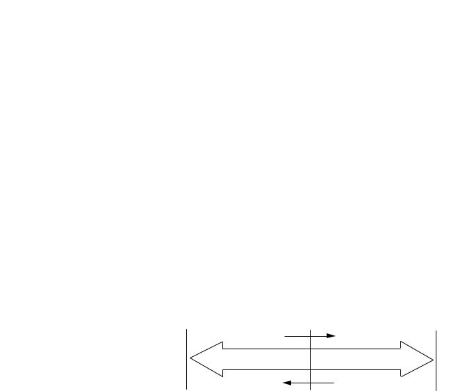
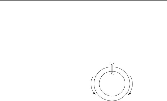
Ring Counter
Rate Value
Figure 2.6 demonstrates ring counter operation. In ring counter operation, the count value changes between programmable minimum and maximum values. If, when counting up, the counter reaches the maximum value, it rolls over to the minimum value. If, when counting down, the counter reaches the minimum value, it rolls over to the maximum value.
Figure 2.6 Ring Counter Diagram
Maximum Value |
Minimum Value |
Rollover
Count Down |
Count Up |
|
The rate value reported to the processor is calculated in counts per second (Hz), and is available with all input configurations. The input configuration determines how the rate value is calculated. When the count value is increasing, the rate value is positive. When the count value is decreasing, the rate value is negative.
The rate value is generally calculated as follows:
When the first input pulse is received, the value of an independent, free-running timer (Ta) is recorded. The module waits approximately 16 ms, while counting more input pulses. After 16 ms, the module waits for the next input pulse, and the value of the independent timer (Tb) is again recorded. The module then calculates the rate value using the formula:
rate value = |
number of counts |
|||
|
-----------------------------------------Tb – Ta |
|
||
|
||||
Publication 1746-UM002B-EN-P - August 2004
Loading...