


 Loading...
Medium Voltage
SMC Flex™
Motor Controller
Bulletins 1503E, 1560E
and 1562E
User Manual

Important User Information
Read this document and the documents listed in the Additional Resources section about installation, configuration, and operation of this equipment before you install, configure, operate, or maintain this product. Users are required to familiarize themselves with installation and wiring instructions in addition to requirements of all applicable codes, laws, and standards.
Activities including installation, adjustments, putting into service, use, assembly, disassembly, and maintenance are required to be carried out by suitably trained personnel in accordance with applicable code of practice.
If this equipment is used in a manner not specified by the manufacturer, the protection provided by the equipment may be impaired.
In no event will Rockwell Automation, Inc. be responsible or liable for indirect or consequential damages resulting from the use or application of this equipment.
The examples and diagrams in this manual are included solely for illustrative purposes. Because of the many variables and requirements associated with any particular installation, Rockwell Automation, Inc. cannot assume responsibility or liability for actual use based on the examples and diagrams.
No patent liability is assumed by Rockwell Automation, Inc. with respect to use of information, circuits, equipment, or software described in this manual.
Reproduction of the contents of this manual, in whole or in part, without written permission of Rockwell Automation, Inc., is prohibited.
Throughout this manual, when necessary, we use notes to make you aware of safety considerations.
WARNING: Identifies information about practices or circumstances that can cause an explosion in a hazardous environment, which may lead to personal injury or death, property damage, or economic loss.
ATTENTION: Identifies information about practices or circumstances that can lead to personal injury or death, property damage, or economic loss. Attentions help you identify a hazard, avoid a hazard, and recognize the consequence.
IMPORTANT Identifies information that is critical for successful application and understanding of the product.
Labels may also be on or inside the equipment to provide specific precautions.
SHOCK HAZARD: Labels may be on or inside the equipment, for example, a drive or motor, to alert people that dangerous voltage may be present.
BURN HAZARD: Labels may be on or inside the equipment, for example, a drive or motor, to alert people that surfaces may reach dangerous temperatures.
ARC FLASH HAZARD: Labels may be on or inside the equipment, for example, a motor control center, to alert people to potential Arc Flash. Arc Flash will cause severe injury or death. Wear proper Personal Protective Equipment (PPE). Follow ALL Regulatory requirements for safe work practices and for Personal Protective Equipment (PPE).
Allen-Bradley, Rockwell Software, Rockwell Automation, and TechConnect are trademarks of Rockwell Automation, Inc.
Trademarks not belonging to Rockwell Automation are property of their respective companies.

|
Table of Contents |
|
|
|
Page |
Preface |
Service Procedure ............................................................................ |
P-1 |
Product Overview |
Chapter 1 |
|
|
Manual Objectives ............................................................................ |
1-1 |
|
Documentation .................................................................................. |
1-1 |
|
Description ........................................................................................ |
1-1 |
|
1503E – OEM Controller ........................................................... |
1-1 |
|
1560E – Retrofit Controller ....................................................... |
1-2 |
|
1562E – Combination Controller ............................................... |
1-2 |
|
SMC-Flex Control Module ......................................................... |
1-2 |
|
Starting Modes .................................................................................. |
1-3 |
|
Soft Start .................................................................................... |
1-3 |
|
Selectable Kickstart .................................................................... |
1-4 |
|
Current Limit Start ..................................................................... |
1-4 |
|
Dual Ramp Start ......................................................................... |
1-5 |
|
Full Voltage Start ....................................................................... |
1-5 |
|
Preset Slow Speed ....................................................................... |
1-6 |
|
Linear Speed Acceleration and Deceleration .............................. |
1-7 |
|
Soft Stop ...................................................................................... |
1-8 |
|
Protection and Diagnostics ............................................................... |
1-9 |
|
Overload ..................................................................................... |
1-9 |
|
Underload .................................................................................. |
1-11 |
|
Undervoltage ............................................................................. |
1-11 |
|
Overvoltage ............................................................................... |
1-11 |
|
Unbalance .................................................................................. |
1-12 |
|
Stall Protection and Jam Detection ........................................... |
1-12 |
|
Ground Fault ............................................................................. |
1-13 |
|
Thermistor/PTC Protection ....................................................... |
1-14 |
|
Open Gate ................................................................................ |
1-16 |
|
Line Faults ................................................................................ |
1-16 |
|
Excessive Starts/Hour .............................................................. |
1-17 |
|
Overtemperature ....................................................................... |
1-17 |
|
Metering.......................................................................................... |
1-17 |
|
Communication ............................................................................... |
1-18 |
|
Programming .................................................................................. |
1-18 |
|
Status Indication ............................................................................. |
1-19 |
|
Control Options .............................................................................. |
1-19 |
|
Pump Control Option ............................................................... |
1-19 |
|
Application Considerations .................................................. |
1-20 |
|
Braking Control Option ............................................................. |
1-21 |
|
Hardware Description ..................................................................... |
1-22 |
|
Power Module .......................................................................... |
1-22 |
|
Self-Powered Silicon-Controlled Rectifier Gate Driver Board .... |
1-22 |
|
Interface Board ......................................................................... |
1-23 |
1560E-UM050B-EN-P - June 2013

ii |
Table of Contents – MV Dialog Plus Medium Voltage Controller User Manual |
Product Overview (cont.) |
Chapter 1 |
Page |
|
Typical MV SMC-Flex Power System Diagrams |
|
|
Bulletin 1562E (Without Stop Control) .................................... |
1-24 |
|
Bulletin 1562E (With Stop Control) .......................................... |
1-25 |
|
Bulletin 1562E (Without Stop Control) ..................................... |
1-26 |
|
Bulletin 1562E (With Stop Control) .......................................... |
1-27 |
|
Functional Descriptions .................................................................. |
1-28 |
|
Bulletin 1562E • Basic Control – Controlled Start Only ......... |
1-28 |
|
Bulletin 1562E • Basic Control – With Controlled Stop ........... |
1-29 |
|
Bulletin 1562E • DPI Control – Controlled Start Only ............. |
1-29 |
|
Bulletin 1560E • Basic Control – Controlled Start Only ......... |
1-30 |
|
Bulletin 1560E • Basic Control – With Controlled Stop ........... |
1-30 |
|
Bulletin 1560E • DPI Control – Controlled Start Only ............. |
1-30 |
|
Schematics: |
|
|
Bul. 1562E IntelliVAC Control Circuit (Without Stop Control) ... |
1-31 |
|
Bul. 1562E IntelliVAC Control Circuit (With Stop Control) ........ |
1-32 |
|
Bul. 1562E IntelliVAC Control Circuit (With DeviceNet) ........... |
1-33 |
|
Bul. 1560E IntelliVAC Control Circuit (Without Stop Control) ... |
1-34 |
|
Bul. 1560E IntelliVAC Control Circuit (With Stop Control) ........ |
1-35 |
|
Bul. 1560E IntelliVAC Control Circuit (With DeviceNet) .......... |
1-36 |
Installation |
Chapter 2 |
|
|
Receiving .......................................................................................... |
2-1 |
|
Safety and Codes .............................................................................. |
2-1 |
|
Unpacking and Inspection ................................................................ |
2-1 |
|
General Precautions .......................................................................... |
2-2 |
|
Transportation and Handling ............................................................ |
2-2 |
|
Installation Site ................................................................................. |
2-3 |
|
Mounting ..................................................................................... |
2-3 |
|
Grounding Practices .................................................................... |
2-4 |
|
Recommended Torque Values ........................................................... |
2-4 |
|
Power Connections ........................................................................... |
2-5 |
|
Bulletin 1562E ............................................................................ |
2-5 |
|
Bulletin 1560E ............................................................................ |
2-8 |
|
Bulletin 1503E .......................................................................... |
2-11 |
|
Power Wiring .................................................................................. |
2-12 |
|
Interlocking ..................................................................................... |
2-12 |
|
Installation ...................................................................................... |
2-13 |
|
Physical Location ...................................................................... |
2-13 |
|
Fan ............................................................................................. |
2-13 |
|
Ground Bus Bar ......................................................................... |
2-13 |
|
Power and Control Wiring ........................................................ |
2-13 |
|
Control Cables ........................................................................... |
2-13 |
|
Fibre-Optic Cables .................................................................... |
2-13 |
|
Power Factor Correction Capacitors ......................................... |
2-14 |
1560E-UM050B-EN-P - June 2013

|
Table of Contents – MV Dialog Plus Medium Voltage Controller User Manual |
iii |
|
Installation (cont.) |
Chapter 2 |
Page |
|
|
Surge Arrestor Protection Devices ................................................. |
2-16 |
|
|
Motor Overload Protection ............................................................. |
2-17 |
|
|
EMC Compliance ............................................................................ |
2-18 |
|
|
Control Power .................................................................................. |
2-19 |
|
|
Control Terminal Designations ...................................................... |
2-20 |
|
Commissioning Procedure |
Chapter 3 |
|
|
|
Preliminary Set-Up ........................................................................... |
3-1 |
|
|
System Characteristics ...................................................................... |
3-2 |
|
|
Preliminary Check ............................................................................ |
3-3 |
|
|
Programming .................................................................................... |
3-3 |
|
|
Hi-Pot and Megger Test .................................................................... |
3-4 |
|
|
Typical MV SMC-Flex Power System Diagram ............................... |
3-5 |
|
|
Connection and Test Information for Interface Board ...................... |
3-6 |
|
|
Power Supply Tests .......................................................................... |
3-7 |
|
|
Control Function Tests ................................................................... |
3-10 |
|
|
Resistance Checks .......................................................................... |
3-11 |
|
|
Voltage Sensing Module ................................................................. |
3-11 |
|
|
Start-Up .......................................................................................... |
3-12 |
|
Programming |
Chapter 4 |
|
|
|
Overview........................................................................................... |
4-1 |
|
|
Keypad Description .......................................................................... |
4-1 |
|
|
Programming Menu .......................................................................... |
4-1 |
|
|
Menu Structure Hierarchy ................................................................. |
4-2 |
|
|
Parameter Linear List ........................................................................ |
4-4 |
|
|
Password ........................................................................................... |
4-5 |
|
|
Parameter Management ................................................................... |
4-6 |
|
|
Parameter Modification .................................................................... |
4-8 |
|
|
Soft Start ........................................................................................... |
4-9 |
|
|
Current Limit Start ............................................................................ |
4-9 |
|
|
Dual Ramp Start ............................................................................. |
4-10 |
|
|
Full Voltage Start ........................................................................... |
4-11 |
|
|
Linear Speed .................................................................................... |
4-11 |
|
|
Basic Setup ..................................................................................... |
4-11 |
|
|
Motor Protection .............................................................................. |
4-13 |
|
|
Example Settings ............................................................................ |
4-13 |
|
|
Motor Information ........................................................................... |
4-15 |
|
1560E-UM050B-EN-P - June 2013

iv |
Table of Contents – MV Dialog Plus Medium Voltage Controller User Manual |
Metering |
Chapter 5 |
Page |
|
Overview........................................................................................... |
5-1 |
|
Motor Data Entry .............................................................................. |
5-1 |
Options |
Chapter 6 |
|
|
Overview........................................................................................... |
6-1 |
|
Human Interface Module .................................................................. |
6-1 |
|
Programming Parameters ................................................................... |
6-3 |
|
Control Wiring ................................................................................... |
6-5 |
Diagnostics |
Chapter 7 |
|
|
Overview........................................................................................... |
7-1 |
|
Fault Display ...................................................................................... |
7-1 |
|
Clear Fault ......................................................................................... |
7-2 |
|
Fault Buffer ........................................................................................ |
7-2 |
|
Fault Contact ...................................................................................... |
7-3 |
|
Fault Definitions ................................................................................ |
7-4 |
Communications |
Chapter 8 |
|
|
Overview............................................................................................ |
8-1 |
|
Communication Ports ........................................................................ |
8-1 |
|
Human Interface Module ................................................................... |
8-1 |
|
Keypad Description ..................................................................... |
8-2 |
|
Connecting the Human Interface Module to the Controller ........ |
8-4 |
|
Control Enable ............................................................................ |
8-4 |
|
Control Enable ................................................................................... |
8-6 |
|
Loss of Communication and Network Faults .................................... |
8-6 |
|
SMC-Flex Specific Information ........................................................ |
8-6 |
|
Default Input/Output Configuration .................................................. |
8-7 |
|
Variable Input/Output Configuration ................................................ |
8-7 |
|
SMC-Flex Bit Identification .............................................................. |
8-8 |
|
Reference/Feedback ........................................................................... |
8-9 |
|
Parameter Information ....................................................................... |
8-9 |
|
Scale Factors for PLC Communication ............................................. |
8-9 |
|
Display Text Unit Equivalents .......................................................... |
8-9 |
|
Configuring DataLinks .................................................................... |
8-10 |
|
Updating Firmware .......................................................................... |
8-10 |
1560E-UM050B-EN-P - June 2013

Table of Contents – MV Dialog Plus Medium Voltage Controller User Manual |
v |
Troubleshooting |
Chapter 9 |
Page |
|
General Notes and Warnings ............................................................ |
9-1 |
|
Fault Display Explanation ................................................................ |
9-3 |
|
Control Module Removal .................................................................. |
9-6 |
|
Voltage Feedback Circuit Tests ......................................................... |
9-7 |
|
Voltage-Sensing Board Replacement ................................................ |
9-8 |
|
IGDPS Boards ................................................................................... |
9-9 |
|
IGDPS Board LEDs ......................................................................... |
9-10 |
|
Circuit Board Replacement .............................................................. |
9-11 |
|
Power Circuit Troubleshooting ....................................................... |
9-12 |
|
Thyristor (SCR) Testing ............................................................ |
9-12 |
|
SCR Replacement Procedure .................................................... |
9-13 |
|
Snubber and Resistor Circuit Testing .............................................. |
9-27 |
|
Snubber Resistor Replacement ........................................................ |
9-30 |
|
Wiring Diagrams ............................................................................. |
9-31 |
Maintenance |
Chapter 10 |
|
|
Safety and Preventative ................................................................... |
10-1 |
|
Periodic Inspection .......................................................................... |
10-1 |
|
Contamination ........................................................................... |
10-1 |
|
Vacuum Bottles ......................................................................... |
10-2 |
|
Terminals .................................................................................. |
10-2 |
|
Coils .......................................................................................... |
10-2 |
|
Solid-State Devices ................................................................... |
10-3 |
|
Static-Sensitive Items ................................................................ |
10-3 |
|
Overload Maintenance After a Fault Condition ........................ |
10-3 |
|
Final Check Out ........................................................................ |
10-3 |
|
"Keep Good Maintenance Records" ......................................... |
10-4 |
|
Power Components ................................................................... |
10-4 |
|
Control Components – Electronic ............................................. |
10-4 |
|
Fans ........................................................................................... |
10-4 |
|
Interlocks ................................................................................... |
10-4 |
|
Barriers ...................................................................................... |
10-4 |
|
Environmental Considerations ......................................................... |
10-5 |
|
Hazardous Materials ................................................................. |
10-5 |
|
Disposal ..................................................................................... |
10-6 |
1560E-UM050A-EN-P – August 2004

vi |
Table of Contents – MV Dialog Plus Medium Voltage Controller User Manual |
Appendix A |
1560E/1562E SMC-Flex Specifications |
Page |
|
Specifications – Table A.1 ............................................................... |
A-1 |
|
Altitude Derating –Table A.2 ........................................................... |
A-3 |
|
Area Available for Cable Entry/Exit – Table A.3 ............................ |
A-3 |
|
Cable Quantity and Size – Table A.4 ............................................... |
A-4 |
|
Shipping Weights and Dimensions – Table A.5 ............................... |
A-5 |
|
Power Bus and Ground Bus – Table A.6 .......................................... |
A-6 |
|
Power Fuses and Losses – Table A.7 ............................................... |
A-7 |
|
Control Wire and Power Wire – Table A.8 ...................................... |
A-8 |
Appendix B |
Parameter Information |
|
|
Parameter List ................................................................................... |
B-1 |
Appendix C |
1560E and 1562E Relay Control |
|
|
Functional Description ..................................................................... |
C-1 |
|
Bulletin 1562E • Basic Control – Controlled Start Only .......... |
C-1 |
|
Bulletin 1562E • Basic Control – With Controlled Stop ............ |
C-2 |
|
Bulletin 1562E • DPI Control – Controlled Start Only .............. |
C-2 |
|
Bulletin 1560E • Basic Control – Controlled Start Only .......... |
C-3 |
|
Bulletin 1560E • Basic Control – With Controlled Stop ............ |
C-3 |
|
Bulletin 1560E • DPI Control – Controlled Start Only .............. |
C-4 |
|
Schematics: |
|
|
Bul. 1562E Relay Control Circuit (Without Stop Control) ............ |
C-5 |
|
Bul. 1562E Relay Control Circuit (With Stop Control) ................. |
C-6 |
|
Bul. 1562E Relay Control Circuit (With DeviceNet) ................... |
C-7 |
|
Bul. 1560E Relay Control Circuit (Without Stop Control) ............ |
C-8 |
|
Bul. 1560E Relay Control Circuit (With Stop Control) ................. |
C-9 |
|
Bul. 1560E Relay Control Circuit (With DeviceNet) ................. |
C-10 |
Appendix D |
Spare Parts |
|
|
Bul. 1503E • 1000-1500V, 180/360A (6-device) ............................. |
D-1 |
|
Bul. 1503E, 1560E, 1562E • 2300V, 180/360A (6-device) .............. |
D-2 |
|
Bul. 1503E, 1560E, 1562E • 2300V, 600A (6-device) ..................... |
D-3 |
|
Bul. 1503E, 1560E, 1562E • 3300/4160V, 180/360A (12-device) ... |
D-4 |
|
Bul. 1503E, 1560E, 1562E • 3300/4160V, 600A (12-device) .......... |
D-5 |
|
Bul. 1503E, 1560E, 1562E • 5500/6900V, 180/360A (18-device) ... |
D-6 |
|
Bul. 1503E, 1560E, 1562E • 5500/6900V, 600A (18-device) .......... |
D-7 |
|
Accessories ....................................................................................... |
D-8 |
Appendix E |
Accessories |
|
|
Accessories ........................................................................................ |
E-1 |
1560E-UM050A-EN-P – August 2004

Preface
Service Procedure |
For your convenience, the Rockwell Automation Global Manufacturing |
|
Solutions (GMS), provides an efficient and convenient method of servicing |
|
medium voltage products. |
|
Contact your local area support office to make arrangements to have a |
|
qualified service representative come to your facility. |
|
A complete listing of Area Support Offices may be obtained by calling your |
|
local Rockwell Automation Distributor or Sales Office. |
For MV SMC-Flex technical support on start-up or existing installations, contact your Rockwell Automation representative. You can also call 1-519-740-4790 for assistance Monday through Friday from 9:00 a.m. to 5:00 p.m. (Eastern time zone).
1560E-UM050B-EN-P - June 2013

Preface
1560E-UM050B-EN-P - June 2013
Chapter 1
Product Overview
Manual Objectives
Documentation
This manual is intended for use by personnel familiar with Medium Voltage and solid-state power equipment. The manual contains material which will allow the user to operate, maintain and troubleshoot the MV SMC-FlexTM family of controllers. The family consists of the following Bulletin numbers: 1503E, 1560E and 1562E.
The following Rockwell Automation publications provide pertinent information for the MV SMC-Flex and components:
• MVB-5.0 |
General Handling Procedures for MV Controllers |
• 1500-UM055B-EN-P |
Medium Voltage Controller Two-High Cabinet |
|
(200A/400A) – User Manual |
•1502-UM050C-EN-P 400A Vacuum Contactor, Series D
–User Manual
•1502-UM052B-EN-P 400A Vacuum Contactor, Series E
–User Manual
•1502-UM051C-EN-P 800A Vacuum Contactor, Series D and E
–User Manual
•1560E-SR022A-EN-P Medium Voltage SMC-Flex Controllers
–General Specifications
Description |
The MV SMC-Flex is a solid-state, three-phase, AC line controller. It is |
|
designed to provide microprocessor-controlled starting and stopping of |
|
standard three-phase, squirrel-cage induction motors, using the same |
|
control module as the Allen-Bradley Bulletin 150 SMC-Flex. |
|
1503E – OEM Controller |
|
A chassis-mount medium voltage solid-state controller designed to mount in |
|
an OEM or customer supplied structure, and designed to work in conjunction |
|
with an existing or OEM/customer supplied starter. It is comprised of |
|
several modular components, including: |
|
• Frame-mounted or loose power stacks including gate driver boards |
|
• Loose interface and voltage feedback boards |
|
• Fiber optic cables for SCR firing |
|
• Microprocessor based control module |
|
• Bypass vacuum contactor |
% 5-" %. 0 *UNE

1-2 Product Overview % 5-" %. 0 *UNE % % 5-" %. 0 *UNE
Description (cont.) 1560E – Retrofit Controller
A medium voltage solid-state controller designed to work in conjunction with an existing customer-supplied starter. It includes:
•Tin-plated, copper, horizontal power bus (optional)
•A continuous, bare copper ground bus
•Power electronics
•A bypass vacuum contactor
•Three (3) current transformers
•A low voltage control panel complete with microprocessor-based control module
•Top and bottom plates to accommodate power cables.
Note: See Interlocking, page 2-8.
1562E – Combination Controller
A medium voltage solid-state controller that provides isolation and protection for new installations. It includes:
•Tin-plated, copper, horizontal power bus (optional)
•A continuous, bare copper ground bus
•Power electronics
•A main non-load-break isolating switch and operating handle
•An isolation vacuum contactor
•A bypass vacuum contactor
•Three (3) current limiting power fuses for NEMA Class E2 operation
•Three (3) current transformers
•A control power transformer (optional)
•A low voltage control panel complete with microprocessor-based control module
•Space for necessary auxiliary control and metering devices
•Top and bottom plates to accommodate power cables
•Motor overload protection (included in SMC-Flex control module)
SMC-Flex™ Control Module
The MV SMC-Flex controller offers a full range of starting and stopping modes as standard:
•Soft Start with Selectable Kickstart
•Soft Stop
•Current Limit Start with Selectable Kickstart
•Linear Acceleration with Selectable Kickstart
•Linear Deceleration
•Dual Ramp Start
•Preset Slow Speed :
•Full Voltage Start
:This option utilizes gating patterns which result in motor and line currents that produce noise and vibration in the motor and/or distribution transformer. This must be considered before applying this option.
% 5-" %. 0 *UNE

Product Overview |
1-3 % 5-" |
|
|
|
|
SMC-Flex™ Control Module (cont.)
Other features that offer further user benefit include:
•Extensive protection features
•Metering
•Communication capability
Innovative control option provides enhanced performance:
• Pump Control (Start and Stop Control modes)
These modes, features and options are further described in this chapter.
:This option utilizes gating patterns which result in motor and line currents that produce noise and vibration in the motor and/or distribution transformer. The factory should be consulted before applying this option.
Starting Modes |
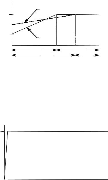
Soft Start |
|||||||||||||||||||||||||
|
This mode has the most general application. The motor is given an initial |
|||||||||||||||||||||||||
|
torque setting, which is user-adjustable from 0 to 90% of locked-rotor |
|||||||||||||||||||||||||
|
torque. From the initial torque level, the output voltage to the motor is |
|||||||||||||||||||||||||
|
steplessly increased during the acceleration ramp time. The acceleration |
|||||||||||||||||||||||||
|
ramp time is user-adjustable from 0 to 30 seconds. Once the MV SMC-Flex |
|||||||||||||||||||||||||
|
controller senses that the motor has reached the up-to-speed condition during |
|||||||||||||||||||||||||
|
the voltage ramp operation, the output voltage automatically switches to |
|||||||||||||||||||||||||
|
full voltage, and the bypass contactor is closed. |
|||||||||||||||||||||||||
|
|
|
|
|
|
|
|
|
|
|
|
|
|
|
|
|
|
|
|
|
|
|
|
|
|
|
|
|
|
|
|
|
|
|
|
|
|
|
|
|
|
|
|
|
|
|
|
|
|
|
|
|
|
|
|
|
|
|
|
|
|
|
|
|
|
|
|
|
|
|
|
|
|
|
|
|
|
|
|
|
|
|
|
|
|
|
|
|
|
|
|
|
|
|
|
|
|
|
|
|
|
|
|
|
|
|
|
|
|
|
|
|
|
|
|
|
|
|
|
|
|
|
|
|
|
|
|
|
|
|
|
|
|
|
|
|
|
|
|
|
|
|
|
|
|
|
|
|
|
|
|
|
|
|
|
|
|
|
|
|
|
|
|
|
|
|
|
|
|
|
|
|
|
|
|
|
|
|
|
|
|
|
|
|
|
|
|
|
|
|
|
|
|
|
|
|
|
|
|
|
|
|
|
|
|
|
|
|
|
|
|
|
|
|
|
|
|
|
|
|
|
|
|
|
|
|
|
|
|
|
|
|
|
|
|
|
|
|
|
|
|
|
|
|
|
|
|
|
|
|
|
|
|
|
|
|
|
|
|
|
|
|
|
|
|
|
|
|
|
|
|
|
|
|
|
|
|
|
|
|
|
|
|
|
|
|
|
|
|
|
|
|
|
|
|
|
Figure 1.1– Soft Start
% 5-" %. 0 *UNE

1-4 Product Overview
Starting Modes (cont.) |
Selectable Kickstart : |
|
Selectable kickstart provides a power boost at start-up that is user-adjustable |
|
from 0 to 90% of locked rotor torque. The additional power helps motors |
|
generate higher torque to overcome the resistive mechanical forces of some |
|
applications when they are started. The selectable kickstart time is user- |
|
adjustable from 0.0 to 2.0 seconds. |
|
Kickstart |
|
100% |
Initial
Torque
Start Run
Time (seconds)
Figure 1.2 – Selectable Kickstart
Current Limit Start ;
This starting mode provides a true current limit start that is used when limiting the maximum starting current is necessary. The Current Limit level is user-adjustable from 50% to 600% of the motor's full-load ampere rating, and the current limit time is user-adjustable from 0 to 30 seconds. Once the MV SMC-Flex™ controller senses that the motor has reached the up-to- speed condition during the current limit starting mode, the output voltage automatically switches to full voltage and the bypass contactor is closed.
600%
Percent Full
Load Current
50%
Start
Time (seconds)
Figure 1.3 – Current Limit Start
:Kickstart is also available with Current Limit Start, Dual Ramp Start and Linear Acceleration.
;The Current Limit Start mode design is based on a motor with a locked-rotor current rating that is 600% of the full-load current rating.
% 5-" %. 0 *UNE
Product Overview |
1-5 |
Dual Ramp Start :
This starting mode is useful for applications that have varying loads (and therefore varying starting torque requirements). Dual Ramp Start allows the user to select between two separate Soft Start profiles with separately adjustable ramp times and initial torque settings.
Percent
Voltage
Ramp #2
100%
Initial Torque #2
Initial Torque #1
Ramp #1 |
|
Start #1 |
Run #1 |
Start #2 |
Run #2 |
Time (seconds) |
|
Figure 1.4 – Dual Ramp Start
:Dual Ramp Start is available only with the standard controller.
Full Voltage Start
This starting mode is used for applications requiring across-the-line starting.
The output voltage to the motor will reach full voltage within ¼ second.
100%
Percent
Voltage
Time (seconds)
Figure 1.5 – Full Voltage Start
% 5-" %. 0 *UNE
1-6 Product Overview
Starting Modes (cont.) |
Preset Slow Speed |
|
|
This option can be used in applications that require a slow-speed jog for |
|
|
general purpose positioning. Preset Slow Speed provides either 7% of |
|
|
base speed (low) or 15% of base speed (high) settings in the forward |
|
|
direction. Reverse can also be programmed and offers 10% of base speed |
|
|
(low) and 20% of base speed (high) settings. |
|
|
|
|
Forward
15% – High
7% – Low
Time (seconds)
Start Run
10% – Low
20% – High
Reverse
Figure 1.6 – Preset Slow Speed Option
Important: Slow speed running is not intended for continuous operation due to reduced motor cooling. The two starts per hour limitation also applies to slow speed operation. This option employs a cycle-skipping scheme which produces limited torque. Applications should be checked with the factory.
% 5-" %. 0 *UNE
Product Overview |
1-7 |
Linear Speed Acceleration and Deceleration
The SMC-Flex has the ability to control the motor speed during starting and stopping maneuvers. A tachometer signal (0 to 5V DC) is required to perform this start mode. The start time is selectable from 0 to 30 seconds and determines the time the motor will ramp from 0 speed to full speed. Kickstart is available with this option.
100%
Motor
Speed
Start |
Run |
Stop |
Time (seconds)
Figure 1.7 – Linear Speed Acceleration
Linear deceleration does not need to be used, even if linear acceleration is used. The stop time can be programmed for 0 to 60 seconds. Linear deceleration cannot brake the motor/load and reduce the stop time.
Note: Consult factory if settings over 30 seconds are required. The base rating of the MV SMC-Flex is two starts (or one start/stop combination) per hour, thirty seconds maximum for each operation. A stopping operation counts as a start for purposes of thermal capacity calculations.
A T T E N T I O N
Linear Deceleration is not intended to be used as an emergency stop. Such usage may result in severe injury or death. Refer to the applicable standards for emergency stop requirements.
% 5-" %. 0 *UNE

1-8 Product Overview % 5-" %. 0 *UNE % % 5-" %. 0 *UNE
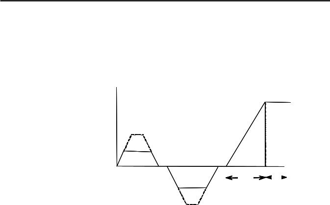
Starting Modes (cont.) Soft Stop
This feature can be used in applications that require an extended coast-to- rest time. The voltage ramp-down time is user-adjustable from 0 to 60 seconds and is adjusted independently from the starting time. The load will stop when the output voltage drops to a point where the load torque is greater than the developed motor torque.
Percent
Voltage
100% |
Kickstart |
Coast-to-rest
 Soft Stop
Initial
Torque
Start |
Run |
Soft Stop |
|
Time (seconds) |
|
Figure 1.8 – Soft Stop Option
Note: Consult factory if settings over 30 seconds are required. The base rating of the MV SMC-Flex is two starts (or one start/stop combination) per hour, thirty seconds maximum for each operation. A stopping operation counts as a start for purposes of thermal capacity calculations.
A T T E N T I O N |
Soft Stop is not intended to be used as an emergency |
|
stop. Such usage may result in severe injury or death. Refer to the applicable standards for emergency stop requirements.
% 5-" %. 0 *UNE
Product Overview |
1-9 |
Protection and Diagnostics
The MV SMC-Flex™ controller is capable of providing the following protective and diagnostic features:
Overload
The MV SMC-Flex controller meets applicable requirements as a motor overload protection device. Thermal memory provides added protection and is maintained even when control power is removed. The built-in overload algorithm controls the value stored in Parameter 12, Motor Thermal Usage (see Chapter 4, Programming). An Overload Fault will occur when this value reaches 100%. The parameters below provide application flexibility and easy setup.
Parameter |
Range |
Overload Class |
Off, 10, 15, 20, 30 |
Overload Reset |
Manual – Auto |
Motor FLC |
1.0 – 1000.0 amps |
Service Factor |
0.01 – 1.99 |
Important: During slow speed operations, current waveforms exhibit non-sinusoidal characteristics. These non-sinusoidal characteristics inhibit the controller's current-measurement capability. To compensate for additional motor heating that may result, the controller uses motor thermal modeling, which increments motor thermal usage. This compensation takes place when the Preset Slow Speed option is used.
Notes:
1.The factory default setting for Overload Class, which is "OFF", disables overload protection. An overload trip class and the motor's full-load current rating must be programmed to enable overload protection.
2.If the MV SMC-Flex is used to control a multi-speed motor, or more than one motor, the Overload Class parameter must be programmed to "OFF" and separate overload relays must be supplied for each speed/motor.
3.Automatic reset of an overload fault requires the start input to be cycled in a 2-wire control scheme.
4.The trip rating is 117% of the programmed FLC.
Figures 1.9 and 1.10 provide the overload trip curves for the available trip classes.
% 5-" %. 0 *UNE

1-10 Product Overview
Protection and Diagnostics (cont.)
Approximate Trip Time (seconds)
1000.0
100.0
10.0
1.0
0.1
|
|
Class 10 |
|
|
|
|
|
|
|
Class 15 |
|
|
|
|
|
|
|
|
Class 20 |
|
|
|
|
|
|
|
Class 30 |
|
|
|
|
||||
|
|
|
|
|
|
|
|
|
10000.0 |
|
|
|
|
|
|
|
|
|
10000.0 |
|
|
|
|
|
|
|
|
|
10000.0 |
|
|
|
|
|
|
|
|
|
|
|
|
|
|
(seconds)Time |
|
|
|
|
|
|
|
|
|
(seconds)Time |
|
|
|
|
|
|
|
|
(seconds)Time |
|
|
|
|
|
|
|
|
|
|
|
|
|
|
|
|
1000.0 |
|
|
|
|
|
|
|
|
1000.0 |
|
|
|
|
|
|
|
|
1000.0 |
|
|
|
|
|
|
|||
|
|
|
|
|
|
|
|
|
|
|
|
|
|
|
|
|
|
|
|
|
|
|
|
|
|
|
|
|
|
|
|
|
|
|
|
|
|
|
|
|
|
|
|
Trip |
100.0 |
|
|
|
|
|
|
|
|
Trip |
100.0 |
|
|
|
|
|
|
|
|
Trip |
100.0 |
|
|
|
|
|
|
|
|
|
|
|
|
|
|
|
|
|
|
|
|
|
|
|
|
|
|
|
|
|
|
|
|
|
|
|
|
|
|||||
|
|
|
|
|
|
|
|
|
|
|
|
|
|
|
|
|
|
|
|
|
|
|
|
|
|
|
|
|
|
|
|
|
|||
|
|
|
|
|
|
|
|
Approximate |
10.0 |
|
|
|
|
|
|
|
|
Approximate |
10.0 |
|
|
|
|
|
|
|
|
Approximate |
10.0 |
|
|
|
|
|
|
1 |
2 |
3 |
4 |
5 |
6 |
7 |
8 9 10 |
|
1.0 |
|
|
|
|
|
|
|
|
|
1.0 |
|
|
|
|
|
|
|
|
|
1.0 |
|
|
|
|
|
|
|
1 |
2 |
3 |
4 |
5 |
6 |
7 |
8 |
9 10 |
|
1 |
2 |
3 |
4 |
5 |
6 |
7 |
8 |
9 10 |
|
1 |
2 |
3 |
4 |
5 |
6 |
7 8 9 10 |
||||||||
Multiples of FLC |
Multiples of FLC |
Multiples of FLC |
Multiples of FLC |
Approximate trip time for 3-phase balanced condition from cold start.
Approximate trip time for 3-phase balanced condition from hot start.
Figure 1.9 – Overload Trip Curves
100000 |
|
1000 |
|
100 |
|
Seconda |
|
10 |
|
1 |
|
0 |
|
100% |
1000% |
Percent Full Load Current Setting
Class 10
Class 15
Class 20
Class 30
Auto Reset Times:
Class 10 = 90 s
Class 15 = 135 s
Class 20 = 180 s
Class 30 = 270 s
Figure 1.10 – Restart Trip Curves after Auto Reset
% 5-" %. 0 *UNE
Product Overview |
1-11 |
Underload :
Utilizing the underload protection of the MV SMC-Flex controller, motor operation can be halted if a sudden drop in current is sensed.
The MV SMC-Flex controller provides an adjustable underload trip setting from 0 to 99% of the programmed motor full load current rating. Trip delay time can be adjusted from 0 to 99 seconds.
: Underload protection is disabled during slow speed and braking operations.
Undervoltage ;
Utilizing the undervoltage protection of the MV SMC-Flex, motor operation can be halted if a sudden drop in voltage is detected.
The MV SMC-Flex controller provides an adjustable undervoltage trip setting from 0 to 99% of the programmed motor voltage. Trip delay time can be adjusted from 0 to 99 seconds.
Note: For medium voltage applications, undervoltage protection should be set from 80 to 99%.
An alarm (pre-fault) indication level can be programmed to indicate the unit is getting close to faulting. The alarm modification information is displayed through the LCD, HIM, Communication (if applicable) and alarm contact closing.
Overvoltage ;
Utilizing the overvoltage protection of the MV SMC-Flex, motor operation can be halted if a sudden increase in voltage is detected.
The MV SMC-Flex controller provides an adjustable overvoltage trip setting from 0 to 199% of the programmed motor voltage. Trip delay time can be adjusted from 0 to 99 seconds.
Note: For medium voltage applications, overvoltage protection should be set from 100 to 115%.
An alarm (pre-fault) indication level can be programmed to indicate the unit is getting close to faulting. The alarm modification information is displayed through the LCD, HIM, Communication (if applicable) and alarm contact closing.
;Undervoltage, overvoltage, and voltage unbalance protection are disabled during braking operation.
% 5-" %. 0 *UNE

1-12 Product Overview
Protection and Diagnostics (cont.)
Unbalance :
The MV SMC-Flex is able to detect an unbalance in line voltages. Motor operation can be halted if the unbalance is greater than the desired range.
The MV SMC-Flex controller provides an adjustable unbalance setting from 0 to 25% of the line voltages. Trip delay time can be adjusted from 0 to 99 seconds.
An alarm (pre-fault) indication level can be programmed to indicate the unit is getting close to faulting. The alarm modification information is displayed through the LCD, HIM, Communication (if applicable) and alarm contact closing.
:Undervoltage, overvoltage, and voltage unbalance protection are disabled during braking operation.
Stall Protection and Jam Detection
The MV SMC-Flex controller provides both stall protection and jam detection for enhanced motor and system protection.
•Stall protection is user-adjustable from 0.0 to 10.0 seconds (enabled only after the programmed start time expires).
•An alarm (pre-fault) indication level can be programmed to indicate the unit is getting close to faulting. The alarm modification information is displayed through the LCD, HIM, Communication (if applicable) and alarm contact closing.
•Jam detection allows the user to determine the jam level (up to 1000% of the motor's full-load current rating) and the delay time (up to 99.0 seconds) for application flexibility.
600% |
|
Percent |
|
Full Load |
|
Current |
|
Programmed Start Time |
Stall |
Time (seconds)
Figure 1.11 – Stall Protection
% 5-" %. 0 *UNE

Product Overview |
1-1 |
Percent |
User Programmed |
Full Load |
Trip Level |
Current |
|
600%
Running |
Jam |
Time (seconds)
Figure 1.12 – Jam Detection :
:Jam Detection is disabled during slow speed and braking operation.
Ground Fault
In isolated or high impedance-grounded systems, core-balanced current sensors are typically used to detect low level ground faults caused by insulation breakdowns or entry of foreign objects. Detection of such ground faults can be used to interrupt the system to prevent further damage, or to alert the appropriate personnel to perform timely maintenance.
The MV SMC-Flex’s ground fault detection capabilities consist of using a core balance current transformer for 1 to 5A core-balanced ground fault protection with the option of enabling Ground Fault Trip, Ground Fault Alarm, or both (a core balance CT is provided with 1562E units).
Ground Fault Trip
The MV SMC-Flex will trip with a ground fault indication if:
•No trip currently exists
•Ground fault protection is enabled
•GF Inhibit Time has expired
•GF Current is equal to or greater than the GF Trip Level for a time period greater than the GF Trip Delay
Parameter 75, Gnd Flt Inh Time, allows the installer to inhibit a ground fault trip from occurring during the motor starting sequence and is adjustable from 0 to 250 seconds.
% 5-" %. 0 *UNE

1-14 Product Overview
Protection and Diagnostics (cont.)
Ground Fault Trip (cont.)
Parameter 74, Gnd Flt Delay, allows the installer to define the time period a ground fault condition must be present before a trip occurs. It is adjustable from 0.1 to 25 seconds.
Parameter 73, Gnd Flt Level, allows the installer to define the ground fault current at which the MV SMC-Flex will trip. It is adjustable from 1.0 to 5.0 A.
Important: The ground fault inhibit timer starts after the maximum phase of load current transitions from 0 A to 30% of the device’s minimum FLA Setting or the GF Current is greater than or equal to 0.5 A. The MV SMC-Flex does not begin monitoring for a ground fault condition until the
Gnd Flt Inh Time expires.
Ground Fault Alarm
The MV SMC-Flex will indicate a Ground Fault Alarm if:
•No warning currently exists
•Ground fault alarm is enabled
•GF Inhibit Time has expired
•GF Current is equal to or greater than the Gnd Flt A Lvl
Parameter 77, Gnd Flt A Lvl, allows the installer to define the ground fault current at which an alarm will be indicated. It is adjustable from 1.0 to 5.0 A.
Parameter 78, Gnd Flt A Dly, allows the installer to define the time period a ground fault alarm condition must be present before a trip occurs. It is adjustable from 0.1 to 25 seconds.
Thermistor/PTC Protection
The MV SMC-Flex provides terminals 23 and 24 for the connection of positive temperature coefficient (PTC) thermistor sensors. PTC sensors are commonly embedded in motor stator windings to monitor the motor winding temperature. When the motor winding temperature reaches the PTC sensor’s temperature rating, the PTC sensor’s resistance transitions from a low to high value. Since PTC sensors react to actual temperature, enhanced motor protection can be provided to address such conditions as obstructed cooling and high ambient temperatures.
The following table defines the MV SMC-Flex PTC thermistor input and response ratings:
% 5-" %. 0 *UNE

Product Overview |
1-15 |
Table 1.A – PTC Input Ratings
Response Resistance |
3400 |
Ω ± 150 Ω |
Reset Resistance |
1600 |
Ω ± 100 Ω |
Short-circuit Trip Resistance |
25 Ω ± 10 Ω |
|
Maximum Voltage at PTC Terminals (RPTC = 4 kΩ) |
< 7.5 V |
|
Maximum Voltage at PTC Terminals (RPTC = open) |
30 V |
|
Maximum Number of Sensors |
6 |
|
Maximum Cold Resistance of PTC Sensor Chain |
1500 |
Ω |
Response Time |
800 ms |
|
The following figure illustrates the required PTC sensor characteristics, per IEC-34-11-2.
4000
1330
550
250
100
20
10
-20°C |
0°C |
TNF-20K |
TNF+15K |
|
TNF5K |
TNF+ 5K |
|
|
|
TNF
Figure 1.13 – PTC Sensor Characteristics per IEC-34-11-2
PTC Trip
The MV SMC-Flex will trip with a PTC indication if:
•No other fault currently exists
•PTC protection is enabled
•The resistance across terminals 23 and 24 is either greater than the relay’s response resistance or less than the short-circuit trip resistance.
% 5-" %. 0 *UNE

1-16 Product Overview
Protection and Diagnostics |
Open Gate |
(cont.) |
|
|
An open-gate fault indicates that improper SCR firing, typically caused by |
|
an open SCR gate or driver system, has been detected on one of the power |
|
poles. Before the controller shuts down, it will attempt to start the motor a |
|
total of three times (or as programmed in Parameter 82). |
|
An open gate is detected when the module sends a gate signal to the SCRs |
|
but does not detect that they turned on. SCR turn-on is detected when the |
|
voltage across the leg (L-T) collapses. |
Line Faults
The MV SMC-Flex™ controller continually monitors line conditions for abnormal factors. Pre-start protection includes:
• Line Fault (with phase indication)
– Line voltage loss
– Missing load connection
– Shorted SCR
Running protection includes:
•Line Fault (no phase indication)
–Line voltage loss
–Missing load connection
Phase reversal protection : can be toggled either ON or OFF.
:Phase reversal protection is functional only at pre-start.
% 5-" %. 0 *UNE
Product Overview |
1-17 |
Excessive Starts/Hour
The MV SMC-Flex™ module allows the user to program the desired number of starts per hour (up to 99). This helps eliminate motor stress caused by repeated starting over a short time period.
Note: The base rating of the MV SMC-Flex is two starts (thirty seconds each max.) per hour. Applications requiring more frequent starts, or longer duration starts, should be reviewed with the factory to avoid equipment damage.
Overtemperature
The power module temperature is monitored during starting and stopping maneuvers by thermistors. The thermistor is connected to the gate driver board where it is processed, and the status is transmitted by fibre-optic cable through the interface board to the control module. When an overtemperature condition exists (>85°C), the control module trips and indicates a "PTC Power Pole" fault.
An overtemperature condition could indicate high ambient temperature, overloading or excessive cycling. After the power module temperature is reduced to allowable levels, the fault can be cleared (see page 9-1 for instructions).
Metering |
Power monitoring parameters include: |
|
|
• Three-phase current |
|
|
• Three-phase voltage |
|
|
• |
Power in MW |
|
• Power usage in MWh |
|
|
• |
Power factor |
|
• Motor thermal capacity usage |
|
|
• |
Elapsed time |
• Motor speed (100%, with use of optional tachometer input)
Notes:
1.Voltage measurement is not available during the braking operation of the SMB Smart Motor Braking, Accu-Stop, and Slow Speed with Braking control options.
2.The elapsed time and MWh values are automatically saved to memory every 12 hours.
3.Motor thermal capacity usage is determined by the built-in electronic thermal overload. An overload fault occurs when this value reaches 100%.
% 5-" %. 0-*UNE

1-18 Product Overview
Communication |
A serial interface port (DPI) is provided as standard, which allows |
|
connection to the Bulletin 20-HIM LCD human interface modules. |
Programming
DPI
Figure 1.14 – DPI Location
A T T E N T I O N
Two peripheral devices can be connected to the DPI. The maximum output current through the DPI is 280 mA.
Setup is easy with the built-in keypad and three-line, sixteen-character backlit LCD. Parameters are organized in a three-level menu structure, using a text format for straightforward programming.
Port 5 – DPI Communications 
Port 2
Ports 2 and 3 when two HIMs are connected with a splitter
Figure 1.15 – Built-in Keypad and LCD
% 5-" %. 0 *UNE
Product Overview |
1-19 |
Status Indication
Four programmable hard contact outputs are provided as standard:
•The Auxiliary #1 Contact is N.O. It is always programmed for Up-to-speed to control the bypass contactor in MV applications.
•The fault Contact is for fault indication and is programmable for N.O./N.C.
•The alarm Contact is for alarm indication and is programmable for N.O./N.C.
•The Auxiliary #2 Contact is for normal indication and is programmable for N.O./N.C. For MV applications, it is configured as N.O. to control the line contactor.
11 |
|
12 |
|
13 |
|
|
14 |
15 |
|
16 |
17 |
|
18 |
19 |
|
20 |
21 |
|
22 |
|||||||||||||||||
|
|
|
|
|
|
|
|
|
|
|
|
|
|
|
|
|
|
|
|
|
|
|
|
|
|
|
|
|
|
|
|
|
|
|
|
|
|
|
|
|
|
|
SMC-Flex |
|
|
|
|
|
|
|
|
|
|
|
|
|
|
|
|
|
|
|
|
|
|
|
|
|
|
||||
|
|
|
|
|
|
|
|
|
|
|
|
|
|
|
|
|
|
|
|
|
|
|
|
|
|
|
|
|
|
|
|
|||||
|
|
|
|
|
|
|
|
|
|
|
|
|
|
|
|
|
|
|
|
|
|
|
|
|
|
|
|
|
|
|
||||||
|
|
|
|
|
|
|
|
|
|
|
|
|
|
|
|
|
|
|
|
|
Aux #1 |
|
|
|
|
|
|
|||||||||
|
|
|
Control Terminals |
|
|
|
|
|
|
|
|
|
|
|
|
Up-to-Speed |
|
|
|
|
|
|
||||||||||||||
|
|
|
|
|
|
|
|
|
|
|
|
|
|
|
|
|
|
|
|
|
|
|
|
|
|
|
|
|
|
|
|
|||||
23 |
|
24 |
|
25 |
|
|
26 |
27 |
|
28 |
29 |
|
30 |
31 |
|
32 |
33 |
|
34 |
|||||||||||||||||
|
|
|
|
|
|
|
|
|
|
|
|
|
|
|
|
|
|
|
|
|
|
|
|
|
|
|
|
|
|
|
|
|
|
|
|
|
|
|
|
|
|
|
|
|
|
|
|
|
|
|
|
|
|
|
|
|
|
|
|
|
|
|
|
|
|
|
|
|
|
|
|
|
|
|
|
|
|
|
|
|
|
|
|
|
|
|
|
|
|
|
|
|
|
|
|
|
|
|
|
|
|
|
|
|
|
|
|
|
|
|
|
|
|
|
|
|
|
|
|
|
|
|
|
|
|
|
|
|
|
|
|
|
|
|
|
|
|
|
|
|
|
|
|
|
|
|
|
PTC |
TACH |
Ground |
Fault |
Alarm |
Aux #2 |
Input |
Input |
Fault |
Contact |
Contact |
Normal |
Figure 1.16 – Control Terminals
Control Options
The MV SMC-Flex™ controller offers the control options described below.
Important: The options listed in this section are mutually exclusive and must be specified when ordering. An existing controller may be upgraded to another control option by replacing the control module and possibly other components. Consult your nearest Rockwell Automation sales office.
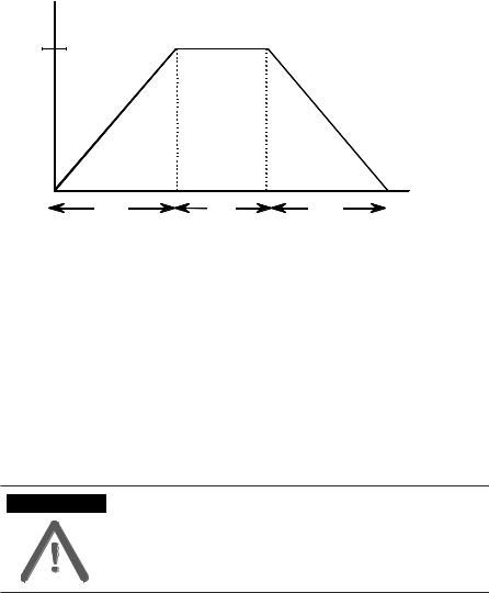
Pump Control Option
This option reduces surges during the starting and stopping of a centrifugal pump by smoothly accelerating and decelerating the motor. The microprocessor analyzes the motor variables and generates commands that control the motor and reduce the possibility of surges occurring in the system.
The motor current will vary during the acceleration period, and may be near the motor rated starting current. The pump algorithm does not limit starting current since full voltage is needed to reach full speed with a loaded motor.
The starting time is programmable from 0-30 seconds, and the stopping time is programmable from 0-120 seconds.
% 5-" %. 0 *UNE

1-20 Product Overview
Control Options (cont.)
Pump Application Considerations
1.Consult factory if start time settings over 30 seconds are required. The base rating of the MV SMC-Flex is two starts (or one start/stop combination) per hour, thirty seconds maximum for each operation. A stopping operation counts as a start for purposes of thermal capacity calculations.
2.The Pump Control option functions only for centrifugal pumps. It is not suited for positive displacement, piston, or other types of pumps.
3.The Pump Stop option functions only for a centrifugal pump running at greater than approximately 2/3 of the motor rated horsepower.
4.Pump applications with input and/or output valves that are closed during starting and/or stopping may not benefit from the Pump Control option. Consult the factory for applications with valves.
5.For starting or stopping times longer than 15 seconds, power fuse selection should be reviewed to ensure no element damage occurs. The fuse minimum melting time-current characteristic curve should be consulted to ensure that, at 1.1 times the full voltage locked rotor current of the motor, the actual starting or stopping time does not exceed 75% of the fuse melting time.
6.Motor overload and/or upstream breaker settings may have to be adjusted to allow the starting or stopping current to flow for extended periods.
100%
Motor
Speed
Pump Start |
Run |
Pump Stop |
Time (seconds)
Figure 1.17 – Pump Control Option
% 5-" %. 0 *UNE
Loading...