


Installation Instructions
Bulletin 1494U Universal Disconnect Switch Installation Instructions (30A, 60A, 100A)
(Cat 1494U-D30; 1494U-D60; 1494U-D100; Series A)
WARNING: To prevent electrical shock, disconnect from power source before installing or servicing. Follow NFPA 70E requirements. Install in suitable enclosure. Keep free from contaminants.
Installation, adjustments, putting into service, use, assembly, disassembly, and maintenance shall be carried out by suitably trained personnel in accordance with applicable code of practice. In case of malfunction or damage, no attempts at repair should be made. The product should be returned to the manufacturer for repair. Do not dismantle the product.
WARNING: The following procedures are critical to the proper operation of the disconnect handle and switch. Failure to follow these steps can result in damage to the equipment and/or serious injury or death to the operator.
Tools Needed: 7/16” Nut Driver, 5/16” Nut Driver, Hammer, Center Punch, File, T27 Torx Driver, Phillips Screwdriver, 11/64” Drill Bit, Needlenose Pliers
Table of Contents |
Page |
Installation Guide............................................................................................................................................................................. |
2 |
Rod and Cable Operated Disconnect Switch Location.................................................................................................. |
2 |
Rod Operated Switch Installation.......................................................................................................................................... |
3 |
Handle Installation.................................................................................................................................................................. |
3 |
Connecting Rod Installation................................................................................................................................................ |
3 |
Rod Adjustment Procedure................................................................................................................................................. |
4 |
Cable Operated Switch Installation...................................................................................................................................... |
5 |
Handle and Cable Mechanism Installation..................................................................................................................... |
5 |
Cable to Switch Mechanism Installation......................................................................................................................... |
6 |
Cable Adjustment Procedure.............................................................................................................................................. |
7 |
Enclosure Without Handle Cutout............................................................................................................................................. |
8 |
Door Catch Bracket Installation.................................................................................................................................................. |
9 |
Trailer Fuse Block and Phase Barrier Installation................................................................................................................ |
10 |
Auxiliary Contact Installation..................................................................................................................................................... |
11 |
Line Terminal Adapter Installation.......................................................................................................................................... |
12 |
Fuse Clip and Fuse Installation................................................................................................................................................. |
13 |
Protective Cover Installation..................................................................................................................................................... |
14 |
Bulletin 1494U Disconnect Switch Component Accessory List.................................................................................... |
15 |
PN-224754
DIR 10001182729 (Version 01)
Printed in U.S.A.
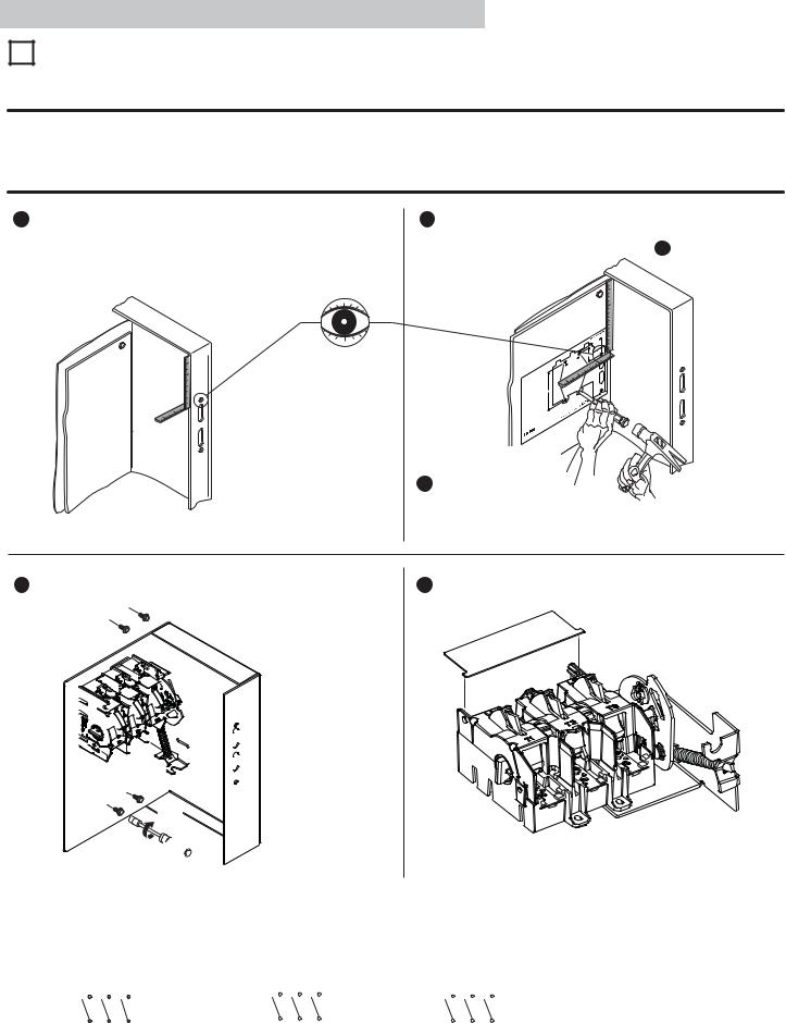
Rod and Cable Operated Disconnect Switch Location
1Disconnect Switch Location and Installation
A)For Rod Operated Switches, follow steps 1 - 5 below.
B)For Cable Operated Switches, follow steps 3 - 5 below.
NOTICE |
When locating the 30A, 60A and 100A cable operated switch, verify that the minimum diameter for the loop of the cable |
between the switch mechanism and handle mechanism is not less than 6 inches. |
Any reduction to the diameter of the bend loop for the cable will reduce the efficiency of the cable system, create additional drag and friction within the cable conduit and possibly decrease system life.
1 Measure top hole of handle on enclosure. |
2 Use template PN-254969 to locate handle holes on mounting plate. |
|
Lay template on enclosure back plate. Align using the top hole on |
Measure hole center to side of enclosure: _______ |
paper and measurements taken from step 1 . |
Measure hole center to top of enclosure: _______ |
|
 2-7/8
2-7/8
-3/4 1
|
|
|
|
|
|
e |
|
|
|
|
|
|
hol |
|
|
|
|
top |
e |
|
|
|
|
|
|
urto |
|
|
|
asurecloser |
||||
|
1: |
Me |
en cent |
|
||
Step |
e one hole e |
er to |
||||
dl |
enclosurle cent |
|
||||
of han· Measure of |
e ho |
re |
|
|
||
|
sid |
|
nclosu |
|
|
|
|
· Measurp of |
|
ate |
on |
||
|
to |
|
|
|
||
|
|
|
mplate |
|
||
|
|
|
te |
pl |
the |
|
p |
2: |
Lay ack ng |
|
d |
||
b usi |
an |
|||||
Stelosureby |
per |
|
|
|||
enc align |
pa |
taken |
||||
d |
le onents |
|
|
|||
an ho |
m1 |
|
|
|
||
top sureep |
|
|
atel |
|||
mea |
St |
|
|
|
||
from |
|
templdril |
||||
|
|
|
e and |
|
|
|
ep |
3: Tapnch, |
|
|
|
||
, pu |
|
|
|
|
||
St wn |
|
|
|
|
|
|
do es |
|
|
|
|
|
|
hol |
|
|
|
|
|
|
|
|
/16 |
|
|
|
|
|
1 |
-13 |
|
|
|
ead |
|
|
|
Holes |
for |
thr |
|
|
|
|
|
switch |
||
|
|
|
ting |
holeswith |
|
|
|
|
Moun11/64"vided |
|
|
||
|
|
(4) |
pro |
|
|
|
|
Switchdrill ews |
|
|
|
||
|
and |
scr |
|
|
|
|
ter |
punch -TITE) |
|
|
|
|
|
(TAP |
|
|
|
|
|
|
Cen |
|
|
|
|
|
|
forming |
|
|
|
|
|
|
7/8 |
|
|
|
|
|
A) |
4- |
|
|
|
Switch100 |
||
|
|
conne |
ct60A |
|
|
|
|
|
- |
|
|
||
|
|
Dis |
(30A |
|
|
|
|
Depth ate |
|
|
|
|
|
|
Templ |
|
|
|
|
|
Variabletion |
|
|
|
|
|
|
|
Loc |
|
|
|
|
|
Hole |
|
|
|
|
|
|
3 Tape template down. Center punch and drill (4)
11/64” holes for thread forming (TAP-TITE) screws provided with switch.
4 Install Disconnect Switch. |
|
|
|
5 Install Line Terminal Guard. |
|||||||||||||||||||||||||||||||||||||
|
|
|
|
|
|
|
|
|
|
|
|
|
|
|
|
|
|
|
|
|
|
|
|
|
|
|
|
|
|
|
|
|
|
|
|
|
|
|
|
|
|
|
|
|
|
|
|
|
|
|
|
|
|
|
|
|
|
|
|
|
|
|
|
|
|
|
|
|
|
|
|
|
|
|
|
|
|
|
|
|
|
|
|
|
|
|
|
|
|
|
|
|
|
|
|
|
|
|
|
|
|
|
|
|
|
|
|
|
|
|
|
|
|
|
|
|
|
|
|
|
|
|
|
|
|
|
|
|
|
|
|
|
|
|
|
|
|
|
|
|
|
|
|
|
|
|
|
|
|
|
|
|
|
|
|
|
|
|
|
|
|
|
|
|
|
|
|
|
|
|
|
|
|
|
|
|
|
|
|
|
|
|
|
|
|
|
|
|
|
|
|
|
|
|
|
|
|
|
|
|
|
|
|
|
|
|
|
|
|
|
|
|
|
|
|
|
|
|
|
|
|
|
|
|
|
|
|
|
|
|
|
|
|
|
|
|
|
|
|
|
|
|
|
|
|
|
|
|
|
|
|
|
|
|
|
|
|
|
|
|
|
|
|
|
|
|
|
|
|
|
|
|
|
|
|
|
|
|
|
|
|
|
|
|
|
|
|
|
|
|
|
|
|
|
|
|
|
|
|
|
|
|
|
|
|
|
|
|
|
|
|
|
|
|
|
|
|
|
|
|
|
|
|
|
|
|
|
|
|
|
|
|
|
|
|
|
|
|
|
|
|
|
|
|
|
|
|
|
|
|
|
|
|
|
|
|
|
|
|
|
|
|
|
|
|
|
|
|
|
|
|
|
|
|
|
|
|
|
|
|
|
|
|
|
|
|
|
|
|
|
|
|
|
|
|
|
|
|
|
|
|
|
|
|
|
|
|
|
|
|
|
|
|
|
|
|
|
|
|
|
|
|
|
|
|
|
|
|
|
|
|
|
|
|
|
|
|
|
|
|
|
|
|
|
|
|
|
|
|
|
|
|
|
|
|
|
|
|
|
|
|
23 - 37 lb-in 
 7/16” Nut Driver
Wiring Diagrams
Single Phase AC |
Three Phase AC |
Direct Current |
||||||||||||
L1 L2 |
L3 |
L1 L2 |
L3 |
L1 L2 |
L3 |
|||||||||
|
|
|
|
|
|
|
|
|
|
|
|
|
|
|
|
|
|
|
|
|
|
|
|
|
|
|
|
|
|
|
|
|
|
|
|
|
|
|
|
|
|
|
|
|
|
|
|
|
|
|
|
|
|
|
|
|
|
|
|
T1 T2 T3 |
T1 T2 T3 |
T1 T2 T3 |
PN-224754 |
|
(2) |
DIR 10001182729 (Version 01) |
|

Rod Operated Switch Installation
1 Handle Installation
1 Install gasket. |
2 Install spring bracket and handle. |
3 Install defeater lever. |
30 - 40 lb-in
7 - 11 lb-in
Spring 
Bracket
Defeater
Lever
2 Cutting Connecting Rod
1 Measure working depth of enclosure.
2 Measure, mark and cut connecting rod. |
3 Remove burrs. |
Mounting |
Enclosure |
|
|
Working Depth |
|
||
Plate |
N |
||
(Inside Flange |
|||
|
|||
|
of Enclosure to |
|
|
|
Mounting Plate) |
|
|
30A - 60A - 100A Disconnect Switches |
|
Connecting Rod |
Enclosure Working Depth “N” |
|
|
Min. |
Max. |
1494U-R1 |
6-1/2” |
19” |
|
|
|
3"
N |
minus |
|
For enclosures with a working depth greater than 19” but less than 23”, use connecting rod kit 1494V-RA4.
3 Connecting Rod Installation
1Verify that disconnect switch and handle are in “OFF” position (Switch blades will be visible).
Drive Bar
2 Rotate connecting rod into drive bar (11) full turns.
See steps 3 and 4 for final rod alignment.
|
Align threaded rod |
4 |
toward handle and, |
|
if needed, rotate |
|
counterclockwise |
|
until ears engage the |
3 |
primary link slots. |
Ensure that the handle is in the full “OFF” position.
PN-224754 |
|
DIR 10001182729 (Version 01) |
(3) |
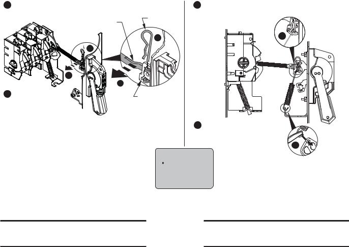
5 Engage ears of connecting rod into slots of handle link.
7 Install spring to handle link.
6Install hitch pin through ears of connecting rod.
Hitch Pin
Connecting
Rod
6
6
5
5
Primary Link
7

8 Install other side of spring to handle bracket.
8
 ATTENTION
CHECK FOR PROPER
OPERATION
Rod Adjustment Procedure
Adjustment Procedure if switch does not turn "ON".
1.Move handle to “ON” position.
2.If switch does not fully close, return handle to "OFF" position.
3.Remove link spring and hitch pin to disengage the connecting rod from the primary link.
4.Turn connecting rod counter-clockwise (1 or more) full turns.
5.Re-engage connecting rod in primary link of handle, insert hitch pin and re-test.
6.Repeat steps 1 - 5 as necessary.
7.Re-install link spring.
Adjustment Procedure if switch does not turn "OFF".
1.Move handle to “OFF” position.
2.If switch does not fully open, return handle to "ON" position.
3.Remove link spring and hitch pin to disengage the connecting rod from the primary link.
4.Turn connecting rod clockwise (1 or more) full turns.
5.Re-engage connecting rod in primary link of handle, insert hitch pin and re-test.
6.Repeat steps 1 - 5 as necessary.
7.Re-install link spring.
PN-224754 |
(4) |
DIR 10001182729 (Version 01) |
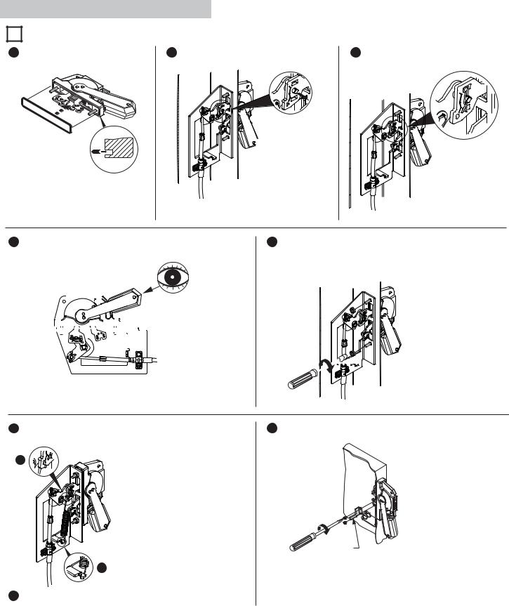
Cable Operated Switch Installation
1 Handle and Cable Mechanism Installation
1 Install gasket. |
2 Connect handle link to lever pin. |
3 Install hitch pin through handle link. |
 TIP: Move handle to

 “ON” position to help connect handle link to lever pin. Return handle to “OFF” position once connected.
4 Verify handle is in “OFF” position. |
|
|
|
5 Install handle nuts. |
||||||||||||
|
|
|
|
|
|
|
|
|
|
|
|
|
|
|
|
|
|
|
|
|
|
|
|
|
|
|
|
|
|
|
|
|
|
|
|
|
|
|
|
|
|
|
|
|
|
|
|
|
|
|
|
|
|
|
|
|
|
|
|
|
|
|
|
|
|
|
|
|
|
|
|
|
|
|
|
|
|
|
|
|
|
|
|
|
|
|
|
|
|
|
|
|
|
|
|
|
|
|
|
|
|
|
|
|
|
|
|
|
|
|
|
|
|
|
|
|
|
|
|
|
|
|
|
|
|
|
|
|
|
|
|
|
|
|
|
|
|
|
|
|
|
|
|
|
|
|
|
|
|
|
|
|
30 - 40 lb-in 


6 Install spring to handle link. |
8 Install defeater lever. |
6
7 - 11 lb-in
Defeater
Lever
7
7Install other end of spring to cable mechanism bracket using needlenose pliers.
PN-224754 |
|
DIR 10001182729 (Version 01) |
(5) |
 Loading...