


 Loading...
Remote I/O Scanner
1747-SN
User Manual
Important User Information Solid state equipment has operational characteristics differing from those of electromechanical equipment. Safety Guidelines for the Application,
Installation and Maintenance of Solid State Controls (Publication SGI-1.1 available from your local Rockwell Automation sales office or online at http://www.ab.com/manuals/gi) describes some important differences between solid state equipment and hard-wired electromechanical devices. Because of this difference, and also because of the wide variety of uses for solid state equipment, all persons responsible for applying this equipment must satisfy themselves that each intended application of this equipment is acceptable.
In no event will Rockwell Automation, Inc. be responsible or liable for indirect or consequential damages resulting from the use or application of this equipment.
The examples and diagrams in this manual are included solely for illustrative purposes. Because of the many variables and requirements associated with any particular installation, Rockwell Automation, Inc. cannot assume responsibility or liability for actual use based on the examples and diagrams.
No patent liability is assumed by Rockwell Automation, Inc. with respect to use of information, circuits, equipment, or software described in this manual.
Reproduction of the contents of this manual, in whole or in part, without written permission of Rockwell Automation, Inc. is prohibited.
Throughout this manual, when necessary we use notes to make you aware of safety considerations.
WARNING
Identifies information about practices or circumstances that can cause an explosion in a hazardous environment, which may lead to personal injury or death, property damage, or economic loss.
IMPORTANT
Identifies information that is critical for successful application and understanding of the product.
ATTENTION
Identifies information about practices or circumstances that can lead to personal injury or death, property damage, or economic loss. Attentions help you:
• identify a hazard
• avoid a hazard
• recognize the consequence
SHOCK HAZARD |
Labels may be located on or inside the equipment (e.g., |
||||
|
|
|
|
|
drive or motor) to alert people that dangerous voltage may |
|
|
|
|
|
be present. |
|
|
|
|
||
|
|
|
|
|
|
|
|
||||
|
|
|
|
|
|
|
|
|
|
|
Labels may be located on or inside the equipment (e.g., |
BURN HAZARD |
|||||
|
|
|
|
|
drive or motor) to alert people that surfaces may be |
|
|
|
|
|
dangerous temperatures. |
|
|
|
|
|
|
|
|
|
|
|
|

Summary of Changes
The information below summarizes the changes to this manual since the last printing. Updates to the manual include using RSLogix 500 instead of APS software.
To help you find new and updated information in this release of the manual, we have included change bars as shown to the right of this paragraph.
The table below lists the sections that document new features and additional or updated information on existing features.
For this information: |
See |
|
|
configuring RIO using G Files |
page 4-4 |
|
|
using block transfer instruction (BTR and |
page 5-5 |
BTW) |
|
|
|
removed Chapter 7 |
application examples can be found in |
|
Chapter 4 and Chapter 5 |
|
|
configuring G files using RSLogix 500 |
page B-9 |
|
|
block transfer examples for earlier |
Appendix D |
processors |
|
|
|
Publication 1747-UM013B-EN-P - January 2005

Summary of Changes |
2 |
|
|
Publication 1747-UM013B-EN-P - January 2005

|
Table of Contents |
|
|
Important User Information . . . . . . . . . . . . . . . . . . . . . . . . |
1-2 |
Table of Contents |
Chapter 1 |
|
Overview |
System Overview . . . . . . . . . . . . . . . . . . . . . . . . . . . . . . . |
1-1 |
|
Scanner I/O Image Division . . . . . . . . . . . . . . . . . . . . . |
1-3 |
|
How the Scanner Scans Remote I/O . . . . . . . . . . . . . . . . . |
1-4 |
|
SLC and Scanner Asynchronous Operation . . . . . . . . . . |
1-4 |
|
How the Scanner Interacts with Adapters . . . . . . . . . . . . . . |
1-5 |
|
Scanner I/O Image Concepts . . . . . . . . . . . . . . . . . . . . . . . |
1-6 |
|
Example Scanner I/O Image. . . . . . . . . . . . . . . . . . . . . |
1-7 |
|
Transferring Data with RIO Discrete and Block Transfers |
1-9 |
|
Physical and Logical RIO Link Specifications . . . . . . . . . |
1-9 |
|
Extended Node Capability . . . . . . . . . . . . . . . . . . . . . . |
1-9 |
|
Complementary I/O . . . . . . . . . . . . . . . . . . . . . . . . . . . |
1-10 |
|
Complementary I/O: Placing Modules with 2-Slot Addressing |
|
|
1-12 |
|
|
Complementary I/O: Placing Modules with 1-Slot Addressing |
|
|
1-13 |
|
|
Complementary I/O: Placing Modules with 1/2-Slot |
|
|
Addressing . . . . . . . . . . . . . . . . . . . . . . . . . . . . . . . . . |
1-14 |
|
Summary for Placing Modules Used In Complementary I/O. |
|
|
1-15 |
|
|
Complementary I/O Application Considerations . . . . . . |
1-17 |
|
Complementary 1771 I/O Module Details . . . . . . . . . . . |
1-17 |
|
Hardware Features . . . . . . . . . . . . . . . . . . . . . . . . . . . . . . |
1-18 |
|
Baud Rate DIP Switch . . . . . . . . . . . . . . . . . . . . . . . . . |
1-18 |
|
LEDs . . . . . . . . . . . . . . . . . . . . . . . . . . . . . . . . . . . . . . |
1-19 |
|
RIO Link Connector . . . . . . . . . . . . . . . . . . . . . . . . . . . |
1-19 |
|
Compatible Devices . . . . . . . . . . . . . . . . . . . . . . . . . . . |
1-19 |
|
Chapter 2 |
|
Quick Start for Experienced Users |
Required Tools and Equipment . . . . . . . . . . . . . . . . . . . . . |
2-1 |
|
Procedures . . . . . . . . . . . . . . . . . . . . . . . . . . . . . . . . . . . . |
2-2 |
|
Chapter 3 |
|
Installation and Wiring |
Compliance to European Union Directives . . . . . . . . . . . . . |
3-1 |
|
EMC Directive . . . . . . . . . . . . . . . . . . . . . . . . . . . . . . . |
3-1 |
|
Baud Rate Selection . . . . . . . . . . . . . . . . . . . . . . . . . . . . . |
3-2 |
|
Scanner Installation . . . . . . . . . . . . . . . . . . . . . . . . . . . . . . |
3-2 |
|
Insertion . . . . . . . . . . . . . . . . . . . . . . . . . . . . . . . . . . . |
3-3 |
|
Removal . . . . . . . . . . . . . . . . . . . . . . . . . . . . . . . . . . . |
3-4 |
|
RIO Link Wiring . . . . . . . . . . . . . . . . . . . . . . . . . . . . . . . . |
3-5 |
|
New Installations . . . . . . . . . . . . . . . . . . . . . . . . . . . . . |
3-6 |
|
For Series A Scanner Retrofits . . . . . . . . . . . . . . . . . . . . |
3-7 |
|
Start Up . . . . . . . . . . . . . . . . . . . . . . . . . . . . . . . . . . . . . . |
3-7 |
|
Scanner Operation . . . . . . . . . . . . . . . . . . . . . . . . . . . . . . |
3-8 |
|
At Power Up . . . . . . . . . . . . . . . . . . . . . . . . . . . . . . . . |
3-8 |
|
In Run Mode . . . . . . . . . . . . . . . . . . . . . . . . . . . . . . . . |
3-8 |
Publication 1747-UM013B-EN-P - January 2005

Table of Contents |
2 |
|
|
|
When Changing From Run Mode . . . . . . . . . . . . . . . . . |
3-8 |
|
Status LEDs. . . . . . . . . . . . . . . . . . . . . . . . . . . . . . . . . . . . |
3-9 |
|
Chapter 4 |
|
Scanner Configuration and |
Understanding Remote Input and Output Image Files. . . . . |
4-1 |
Programming |
RIO Configuration Using G Files . . . . . . . . . . . . . . . . . . . . |
4-4 |
|
Rules for Configuring the Scanner. . . . . . . . . . . . . . . . . |
4-7 |
|
Considerations When Configuring Remote I/O . . . . . . . . . . |
4-12 |
|
G File Considerations. . . . . . . . . . . . . . . . . . . . . . . . . . |
4-12 |
|
Crossing Logical Rack Boundaries . . . . . . . . . . . . . . . . |
4-13 |
|
Understanding M Files. . . . . . . . . . . . . . . . . . . . . . . . . . . . |
4-14 |
|
M Files Overview. . . . . . . . . . . . . . . . . . . . . . . . . . . . . |
4-14 |
|
M0 Control File Description . . . . . . . . . . . . . . . . . . . . . |
4-16 |
|
M0 File - RIO Device Inhibit Control. . . . . . . . . . . . . . . |
4-17 |
|
M0 File - RIO Device Reset Control. . . . . . . . . . . . . . . . |
4-18 |
|
M0 File - Remote Output Reset Control. . . . . . . . . . . . . |
4-19 |
|
Device Reset and Remote Output Reset Considerations. . . . |
4-21 |
|
M1 Status File Description . . . . . . . . . . . . . . . . . . . . . . . . . |
4-23 |
|
General Communication Status - Enable Device Fault Bit |
. . . |
|
4-23 |
|
|
General Communication Status - Communication Attempted |
|
|
Bit. . . . . . . . . . . . . . . . . . . . . . . . . . . . . . . . . . . . . . . . |
4-23 |
|
RIO Baud Rate Status . . . . . . . . . . . . . . . . . . . . . . . . . . |
4-24 |
|
Logical Device Starting Address Status . . . . . . . . . . . . . |
4-24 |
|
Logical Device Image Size Status . . . . . . . . . . . . . . . . . |
4-25 |
|
Active Device Status. . . . . . . . . . . . . . . . . . . . . . . . . . . |
4-26 |
|
Logical Device Fault Status . . . . . . . . . . . . . . . . . . . . . . |
4-27 |
|
RIO Status Example . . . . . . . . . . . . . . . . . . . . . . . . . . . |
4-28 |
|
RIO Communication Retry Counter (M1:e.16 -47) . . . . . . . . |
4-30 |
|
Understanding Slot Addressing . . . . . . . . . . . . . . . . . . . . . |
4-32 |
|
SLC/Scanner Configuration . . . . . . . . . . . . . . . . . . . . . . . . |
4-33 |
|
Chapter 5 |
|
RIO Block Transfer |
RIO Block Transfer Theory of Operation . . . . . . . . . . . . . . |
5-1 |
|
What Is RIO Block Transfer? . . . . . . . . . . . . . . . . . . . . |
5-1 |
|
Using Block Transfer Instructions (BTR and BTW) . . . . . . . |
5-5 |
|
RIO Block Transfer General Functional Overview . . . . . |
5-5 |
|
Parameters for BTR and BTW . . . . . . . . . . . . . . . . . . . . |
5-6 |
|
Control Status Bits . . . . . . . . . . . . . . . . . . . . . . . . . . . . |
5-7 |
|
Instruction Operation . . . . . . . . . . . . . . . . . . . . . . . . . . |
5-11 |
|
Programming Examples . . . . . . . . . . . . . . . . . . . . . . . . |
5-12 |
|
Comparison to the PLC-5 BTR and BTW . . . . . . . . . . . . |
5-16 |
|
Chapter 6 |
|
Troubleshooting |
Troubleshooting . . . . . . . . . . . . . . . . . . . . . . . . . . . . . . . . |
6-1 |
Publication 1747-UM013B-EN-P - January 2005

|
Table of Contents 3 |
|
|
|
|
|
Error Codes . . . . . . . . . . . . . . . . . . . . . . . . . . . . . . . . . . . |
6-2 |
|
Retry Counters . . . . . . . . . . . . . . . . . . . . . . . . . . . . . . . . . |
6-2 |
|
Block Transfers . . . . . . . . . . . . . . . . . . . . . . . . . . . . . . . . . |
6-2 |
|
Appendix A |
|
Specifications |
Scanner Operating Specifications . . . . . . . . . . . . . . . . . . . . |
A-1 |
|
Network Specifications . . . . . . . . . . . . . . . . . . . . . . . . . . . |
A-1 |
|
Throughput Introduction . . . . . . . . . . . . . . . . . . . . . . . . . . |
A-2 |
|
RIO Network Throughput Components. . . . . . . . . . . . . |
A-2 |
|
Calculating Throughput . . . . . . . . . . . . . . . . . . . . . . . . . . . |
A-3 |
|
Discrete I/O Throughput without Block Transfers (Tdm-nbt) |
|
|
Present . . . . . . . . . . . . . . . . . . . . . . . . . . . . . . . . . . . . |
A-3 |
|
Discrete I/O Throughput with Block Transfers (Tdm-bt) |
|
|
Present . . . . . . . . . . . . . . . . . . . . . . . . . . . . . . . . . . . . |
A-6 |
|
Block Transfer Throughput . . . . . . . . . . . . . . . . . . . . |
A-10 |
|
RIO Scanner Output Delay Time (TSNo) Tables . . . . . |
A-13 |
|
Appendix B |
|
M0 - M1 Files and G Files |
M0 - M1 Files . . . . . . . . . . . . . . . . . . . . . . . . . . . . . . . . . . |
B-1 |
|
Addressing M0-M1 Files . . . . . . . . . . . . . . . . . . . . . . . . |
B-2 |
|
Restrictions on Using M0-M1 Data File Addresses . . . . . |
B-2 |
|
Monitoring Bit Addresses . . . . . . . . . . . . . . . . . . . . . . . |
B-2 |
|
Transferring Data Between Processor Files and M0 or M1 Files |
|
|
B-4 |
|
|
Access Time . . . . . . . . . . . . . . . . . . . . . . . . . . . . . . . . |
B-4 |
|
Minimizing the Scan Time . . . . . . . . . . . . . . . . . . . . . . |
B-7 |
|
Capturing M0-M1 File Data. . . . . . . . . . . . . . . . . . . . . . |
B-8 |
|
Specialty I/O Modules with Retentive Memory . . . . . . . |
B-8 |
|
G Files . . . . . . . . . . . . . . . . . . . . . . . . . . . . . . . . . . . . . . . |
B-9 |
|
Configuring G Files using RSLogix 500 . . . . . . . . . . . . . |
B-9 |
|
After all devices have been properly mapped, click OK and |
|
|
the G file is automatically configured. This procedure |
|
|
eliminates the bit by bit process needed to configure the G |
|
|
file with other programming tools. . . . . . . . . . . . . . . . |
B-13 |
|
Editing G File Data . . . . . . . . . . . . . . . . . . . . . . . . . . |
B-14 |
|
Appendix C |
|
RIO Configuration Worksheet |
Directions . . . . . . . . . . . . . . . . . . . . . . . . . . . . . . . . . . . . . |
C-1 |
Appendix D
Block Transfer Examples for Earlier Processors
BTR and BTW Control Logic Examples . . . . . . . . . . . . . . . D-1 Block Transfer Read Control Logic Example . . . . . . . . . D-1 Block Transfer Write Control Logic Example . . . . . . . . D-4 Directional Continuous Block Transfer Example . . . . . . D-6 Directional Repeating Block Transfer Example . . . . . . . D-9
Publication 1747-UM013B-EN-P - January 2005

Table of Contents |
4 |
|
|
|
Directional Non-Continuous Block Transfer Example . |
D-12 |
|
Bidirectional Continuous Block Transfer Example . . . . |
D-16 |
|
Bidirectional Alternating Block Transfer . . . . . . . . . . . |
D-21 |
Glossary |
Bidirectional Alternating Repeating Block Transfer . . . |
D-27 |
|
|
|
Index |
Rockwell Automation Support . . . . . . . . . . . . . . . . . . . . . . |
1-7 |
|
Installation Assistance . . . . . . . . . . . . . . . . . . . . . . . . . |
1-7 |
|
New Product Satisfaction Return . . . . . . . . . . . . . . . . . . |
1-7 |
Publication 1747-UM013B-EN-P - January 2005

Chapter 1
Overview
System Overview
This chapter contains the following information:
•system overview
•how the scanner interacts with the SLC processor
•how the scanner interacts with adapter modules
•scanner I/O image concepts
•extended node capability
•complementary I/O
•scanner features
•compatible network devices
The Remote I/O (RIO) Scanner, Catalog Number 1747-SN, is the remote I/O scanner for the SLC 500. It enables communication between an SLC processor (SLC 5/02 or later) and remotely located (3,048 meters [10,000 feet] maximum) 1746 I/O chassis and other RIO compatible Allen-Bradley operator interface and control devices. The 1747-SN Scanner communicates with remotely located devices using the Allen-Bradley Remote I/O link. The RIO link consists of a single master (scanner) and multiple slaves (adapters). Communication between devices occurs over twisted pair cable with the devices daisy-chained together. The scanner can reside in any slot of the local SLC chassis except for slot 0.
The Remote I/O (RIO) Scanner, Catalog Number 1747-SN, is the remote I/O scanner for the SLC 500. It enables communication between an SLC processor (SLC 5/02 or later) and remotely located (3,048 meters [10,000 feet] maximum) 1746 I/O chassis and other RIO compatible Allen-Bradley operator interface and control devices. The 1747-SN Scanner communicates with remotely located devices using the Allen-Bradley Remote I/O link. The RIO link consists of a single master (scanner) and multiple slaves (adapters). Communication between devices occurs over twisted pair cable with the devices daisy-chained together. The scanner can reside in any slot of the local SLC chassis except for slot 0.
Publication 1747-UM013B-EN-P - January 2005

1-2 Overview
SLC 5/02 |
RIO Scanner |
|
or Later |
(Master of the |
|
Processor |
RIO Link) |
|
|
The scanner transfers input and |
|
|
output data between itself and all |
|
|
configured network devices over |
|
|
twisted pair cable. Note that the |
|
|
end-to-end length of the cable can be |
1747-ASB Module |
|
a maximum of 3,048 meters (10,000 |
(Adapter/Slave) |
|
feet). |
|
|
Local SLC Chassis |
|
|
Remote Chassis |
|
Remote Expansion Chassis
Dataliner Message Display |
PanelView Operator Terminal |
RediPANEL |
(Adapter/Slave) |
(Adapter/Slave) |
(Adapter/Slave) |
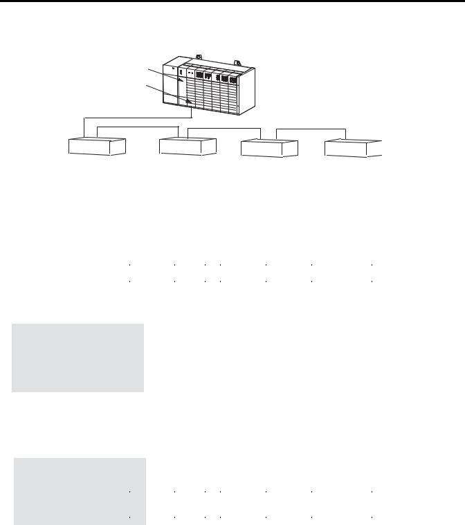
The scanner can be configured for and transfer a maximum of 4 logical racks of discrete data on the RIO link. The scanner provides discrete I/O and block (Series B or later) transfers. Configurations allowed are any combination of quarter, half, three-quarter, or full logical rack devices.
SLC 5/02 |
RIO |
or Later |
Scanner |
Processor |
|
The scanner transfers discrete input and output data between itself, remote adapters, and the SLC processor. . Remote adapters consist of 1746 chassis and other Allen-Bradley operator interface and control devices.
Adapter 1 |
Adapter 2 |
Adapter 3 |
Adapter 4 |
Adapter 5 |
Adapter 6 |
Half Logical |
Quarter Logical |
Half |
Three-Quarter |
Full |
Full |
Rack |
Rack |
Logical Rack |
Logical Rack |
Logical Rack |
Logical Rack |
Device |
Device |
Device |
Device |
Device |
Device |
The SLC processor transfers the scanner’s 4 logical racks (32 input image and 32 output image words) of discrete remote I/O image data into the SLC input and output image files. You can adjust the size of the scanner input and output image file during configuration of your SLC system so that the scanner only transfers the discrete I/O data
Publication 1747-UM013B-EN-P - January 2005
Overview 1-3
your application program requires. Configuration is done through the confiGuration file (G file). Refer to Chapter 4, Configuration and Programming, for more information.
IMPORTANT |
The SLC 500 processor (SLC 5/02 or later) supports |
|
multiple scanners in its local I/O chassis. The |
||
|
||
|
||
|
maximum number is dependent on the following: |
|
|
• backplane power requirements (power supply |
|
|
dependent) |
|
|
• SLC 500 processor I/O data table limit (4,096 I/O) |
|
|
• processor memory to support the application |
|
|
(SLC 500 processor dependent) |
|
|
|
Scanner I/O Image Division
The scanner allows each adapter to use a fixed amount (user defined) of the scanner’s input and output image. Part of the SLC processor’s image is used by local I/O, the other portion is used by the scanner for remote I/O.
The scanner remote I/O image is divided into logical racks and further divided into logical groups. A full logical rack consists of eight input and eight output image words. A logical group consists of one input and one output word in a logical rack. Each logical group is assigned a number from 0 to 7.
Local I/O
|
|
Logical Rack 0 |
|
|
|
|
|
|
|
|
|
|
|
||
Remote I/O |
Logical Rack 1 |
|
|
|
|
|
|
|
|
|
|
|
|||
|
|
|
|
||||
|
|
|
|
|
|
||
(Scanner Image) |
|
|
|
|
|
|
|
|
|
|
Logical Group 0 |
|
|
||
|
|
|
|
|
|
|
|
|
|
Logical Rack 2 |
|
|
Logical Group 7 |
|
|
|
|
|
|
|
|||
|
|
|
|
|
|
|
|
Processor I/O Image |
|
|
|
Scanner I/O Image |
Adapter |
||
|
|
|
|
|
|
|
Image |
Publication 1747-UM013B-EN-P - January 2005

1-4 Overview
How the Scanner Scans
Remote I/O
The scanner image contains the image of each adapter on the RIO link. The adapter is assigned a portion of the scanner image, which is referred to as the adapter image.
The scanner communicates with each logical device in a sequential fashion. First, the scanner initiates communication with a device by sending output data to the device. The device then responds by sending its input data back to the scanner, as illustrated below. You refer to this exchange as a discrete I/O transfer. After the scanner completes its discrete I/O transfer with the last configured network device, it begins another discrete I/O transfer with the first device.
It is important to understand that the scanner transfers RIO data on a logical device basis not on an adapter basis. A logical device is a full logical rack or portion of a logical rack assigned to an adapter.
RIO Scanner Scan
The scanner updates its input image file each time it scans a logical device.
Scanner |
Output |
Input |
|
Input |
|||
Device 3 |
Device 1 |
||
Image File |
|||
|
|
||
Input |
|
Output |
|
Device 3 |
|||
Device 1 |
|||
|
|
||
|
Output |
Input |
|
|
Device 2 |
Device 2 |
|
Scanner Output
Image File
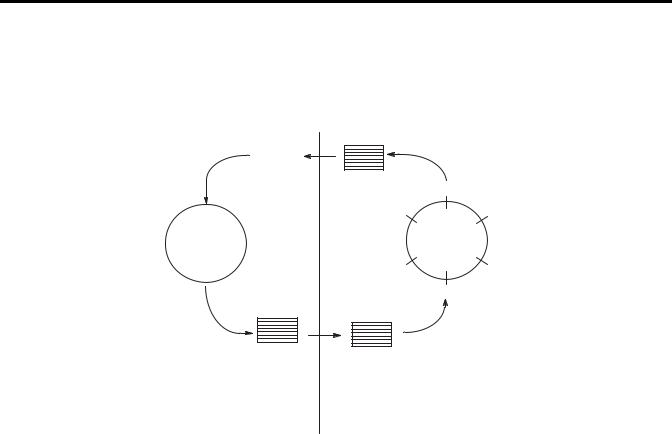
SLC and Scanner Asynchronous Operation
The SLC processor scan and RIO scanner scan are independent (asynchronous) of each other. The SLC processor reads the scanner input image file during its input scan and writes the output image file to the scanner during its output scan. The RIO scanner continues reading inputs and writing outputs to the scanner I/O image file, independent of the SLC processor scan cycle.
Depending on your SLC processor, RIO link configuration, and application program size, the scanner may complete multiple scans before the SLC processor reads the scanner’s input image file. The RIO scanner updates its I/O files on a per logical rack basis.
Publication 1747-UM013B-EN-P - January 2005
Overview 1-5
The figure below illustrates the asynchronous operation of the SLC processor and RIO scanner.
SLC Processor Scan Cycle
The SLC processor reads the
scanner input image file into the
SLC input image file, processes Program it, and creates an SLC output
image file. The SLC processor transfers its output file to the scanner..
SLC Processor
|
|
|
|
|
RIO Scanner Scan Cycle |
|
|
|
|
|
|
||
|
|
|
|
|
||
|
|
|
|
|
||
|
|
|
|
|
||
|
|
|
Scanner |
Output |
Input |
|
|
|
|
|
|||
|
|
|
|
|||
|
|
|
|
|||
|
|
|
|
|||
|
|
|
|
|||
|
|
|
|
|||
|
|
|
|
|||
|
|
|
Image |
Image |
|
|
SLC Input |
Input |
|
||||
Device 3 |
Device 1 |
|
||||
Image File |
Image File |
|
||||
|
|
The scanner updates its |
||||
|
|
|
|
|
|
|
|
|
|
Input |
|
Output |
input image file each time |
|
|
|
|
it scans a logical device. |
||
|
|
|
Image |
|
Image |
The scanner may scan all |
|
|
|
Device 3 |
Device 1 |
of its configured logical |
|
|
|
|
|
|
|
devices several times |
|
|
|
|
Output |
Input |
before the SLC processor |
|
|
|
|
reads the scanner's input |
||
|
|
|
|
Image |
Image |
|
|
|
|
|
image file. |
||
|
|
|
|
Device 2 |
Device 2 |
|
|
|
|
|
|
||
|
|
|
Scanner Output |
|
|
|
SLC Output |
|
|
||||
Image File |
|
|
|
|||
Image File |
|
|
|
|
||
Important: The outputs of the RIO are updated after the end of the first SLC processor scan.
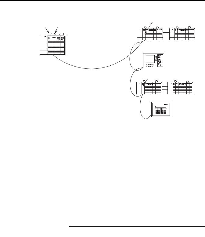
How the Scanner Interacts with Adapters
The scanner’s function is to continuously scan the adapters on the RIO link in a consecutive manner. This scan consists of one or more RIO discrete transfers to each adapter on the RIO link.
RIO discrete transfers consist of the scanner sending output image data and communication commands to the adapter that instruct the adapter on how to control its output. (These include run, adapter reset, and reset decide commands.) The adapter responds by sending input data to the scanner. The scanner performs as many RIO discrete transfers as necessary to update the entire adapter image. If RIO discrete transfers do not occur, data is not exchanged between the scanner and adapter. RIO discrete transfers are asynchronous to the processor scan.
Publication 1747-UM013B-EN-P - January 2005
1-6 Overview
Processor Scanner
RIO Discrete
Transfers
with Adapter 1
SLC Local Chassis
RIO Discrete
Transfers
with Adapter 2
PanelView Operator
Terminal
RIO Discrete
Transfers
with Adapter 3
RIO Discrete
Transfers
with Adapter 4
RediPANEL
Scanner I/O Image
Concepts
The scanner’s I/O image consists of RIO logical racks and I/O groups. A full RIO logical rack consists of eight input image and eight output image words. (A word consists of 16 bits of data.) Each word within an RIO logical rack is assigned an I/O group number from 0 to 7.
You assign devices on the RIO link a portion of the scanner’s image. Devices can occupy a quarter logical rack (2 input and output words), half logical rack (4 I/O words), three-quarter logical rack (6 I/O words), or full logical rack. You may configure devices to start at any even I/O group number within an RIO logical rack. More than one physical device’s (adapter) I/O information can reside in a single logical rack. Also, by crossing logical rack boundaries, a device can consist of more than one logical rack.
|
The following illustration shows only the input |
|
IMPORTANT |
||
image configuration of the scanner’s I/O image. The |
||
|
||
|
||
|
output image configuration is the same. |
|
|
|
Publication 1747-UM013B-EN-P - January 2005

Overview 1-7
RIO
Logical
Rack 0
RIO
Logical
Rack 1
RIO
Logical
Rack 2
RIO
Logical
Rack 3
Input Image Half of a Scanner's I/O Image
Bit Number (decimal) |
15 |
14 |
13 |
12 |
11 |
10 |
9 |
8 |
7 |
6 |
5 |
4 |
3 |
2 |
1 |
0 |
|
|
|
|
Rack 0 Group 0 |
Word 0 |
|
|
|
|
|
|
|
|
|
|
|
|
|
|
|
|
|
|
Quarter Logical |
|
|
|
|
|
|
|
|
|
|
|
|
|
|
|
|
|
|
|||
Rack 0 Group 1 |
Word 1 |
|
|
|
|
|
|
|
|
|
|
|
|
|
|
|
|
|
|
Rack |
Rack 0 Group 2 |
Word 2 |
|
|
|
|
|
|
|
|
|
|
|
|
|
|
|
|
|
|
|
Rack 0 Group 3 |
Word 3 |
|
|
|
|
|
|
|
|
|
|
|
|
|
|
|
|
|
|
Not Used In This |
Rack 0 Group 4 |
Word 4 |
|
|
|
|
|
|
|
|
|
|
|
|
|
|
|
|
|
|
|
Rack 0 Group 5 |
Word 5 |
|
|
|
|
|
|
|
|
|
|
|
|
|
|
|
|
|
|
Example |
Rack 0 Group 6 |
Word 6 |
|
|
|
|
|
|
|
|
|
|
|
|
|
|
|
|
|
|
|
Rack 0 Group 7 |
Word 7 |
|
|
|
|
|
|
|
|
|
|
|
|
|
|
|
|
|
|
|
|
|
|
|
|
|
|
|
|
|
|
|
|
|
|
|
|
|
|
||
Rack 1 Group 0 |
Word 8 |
|
|
|
|
|
|
|
|
|
|
|
|
|
|
|
|
|
|
Half Logical |
Rack 1 Group 1 |
Word 9 |
|
|
|
|
|
|
|
|
|
|
|
|
|
|
|
|
|
|
|
Rack 1 Group 2 |
Word 10 |
|
|
|
|
|
|
|
|
|
|
|
|
|
|
|
|
|
|
Rack |
Rack 1 Group 3 |
Word 11 |
|
|
|
|
|
|
|
|
|
|
|
|
|
|
|
|
|
|
|
Rack 1 Group 4 |
Word 12 |
|
|
|
|
|
|
|
|
|
|
|
|
|
|
|
|
|
|
Not Used In This |
|
|
|
|
|
|
|
|
|
|
|
|
|
|
|
|
|
|
|||
Rack 1 Group 5 |
Word 13 |
|
|
|
|
|
|
|
|
|
|
|
|
|
|
|
|
|
|
|
|
|
|
|
|
|
|
|
|
|
|
|
|
|
|
|
|
|
Example |
||
Rack 1 Group 6 |
Word 14 |
|
|
|
|
|
|
|
|
|
|
|
|
|
|
|
|
|
|
|
Rack 1 Group 7 |
Word 15 |
|
|
|
|
|
|
|
|
|
|
|
|
|
|
|
|
|
|
|
|
|
|
|
|
|
|
|
|
|
|
|
|
|
|
|
|
|
|
||
Rack 2 Group 0 |
Word 16 |
|
|
|
|
|
|
|
|
|
|
|
|
|
|
|
|
|
|
|
Rack 2 Group 1 |
Word 17 |
|
|
|
|
|
|
|
|
|
|
|
|
|
|
|
|
|
|
Three-Quarter |
Rack 2 Group 2 |
Word 18 |
|
|
|
|
|
|
|
|
|
|
|
|
|
|
|
|
|
|
|
|
|
|
|
|
|
|
|
|
|
|
|
|
|
|
|
|
|
Logical Rack |
||
Rack 2 Group 3 |
Word 19 |
|
|
|
|
|
|
|
|
|
|
|
|
|
|
|
|
|
|
|
|
|
|
|
|
|
|
|
|
|
|
|
|
|
|
|
|
|
|
||
Rack 2 Group 4 |
Word 20 |
|
|
|
|
|
|
|
|
|
|
|
|
|
|
|
|
|
|
|
Rack 2 Group 5 |
Word 21 |
|
|
|
|
|
|
|
|
|
|
|
|
|
|
|
|
|
|
Not Used In This |
Rack 2 Group 6 |
Word 22 |
|
|
|
|
|
|
|
|
|
|
|
|
|
|
|
|
|
|
|
Rack 2 Group 7 |
Word 23 |
|
|
|
|
|
|
|
|
|
|
|
|
|
|
|
|
|
|
Example |
|
|
|
|
|
|
|
|
|
|
|
|
|
|
|
|
|||||
|
|
|
|
|
|
|
|
|
|
|
|
|
|
|
|
|
|
|||
Rack 3 Group 0 |
Word 24 |
|
|
|
|
|
|
|
|
|
|
|
|
|
|
|
|
|
|
|
Rack 3 Group 1 |
Word 25 |
|
|
|
|
|
|
|
|
|
|
|
|
|
|
|
|
|
|
|
Rack 3 Group 2 |
Word 26 |
|
|
|
|
|
|
|
|
|
|
|
|
|
|
|
|
|
|
Full |
|
|
|
|
|
|
|
|
|
|
|
|
|
|
|
|
|
||||
Rack 3 Group 3 |
Word 27 |
|
|
|
|
|
|
|
|
|
|
|
|
|
|
|
|
|
|
Logical |
Rack 3 Group 4 |
Word 28 |
|
|
|
|
|
|
|
|
|
|
|
|
|
|
|
|
|
|
Rack |
Rack 3 Group 5 |
Word 29 |
|
|
|
|
|
|
|
|
|
|
|
|
|
|
|
|
|
|
|
Rack 3 Group 6 |
Word 30 |
|
|
|
|
|
|
|
|
|
|
|
|
|
|
|
|
|
|
|
Rack 3 Group 7 |
Word 31 |
|
|
|
|
|
|
|
|
|
|
|
|
|
|
|
|
|
|
|
Bit Number (octal) |
17 8 |
16 8 |
15 8 |
14 8 |
13 8 |
12 8 |
11 8 |
10 8 |
78 |
68 |
58 |
48 |
38 |
28 |
18 |
08 |
|
|
|
|
Example Scanner I/O Image
The illustrations below show a scanner’s input image of 4 RIO link devices.
Publication 1747-UM013B-EN-P - January 2005
1-8 Overview
SLC 5/02 or Later Processor
RIO
Scanner
Device 1 |
Device 2 |
Device 3 |
Device 4 |
|
Full Logical Rack |
Three-Quarter Logical |
Half Logical Rack |
Quarter Logical Rack |
|
Device |
Rack Device |
Device |
Device |
|
Begins at Logical |
Begins at Logical |
Begins at Logical |
Begins at Logical |
|
Rack 0, Group 0. |
Rack 1, Group 0. |
Rack 2, Group 0. |
Rack 2, Group 4. |
|
Important: The illustration below shows only the scanner's input image. The output image looks the same.
RIO
Logical
Rack 0
RIO
Logical
Rack 1
RIO
Logical
Rack 2
RIO
Logical
Rack 3
|
Bit Number |
15 |
14 |
13 |
12 |
11 |
10 |
9 |
8 |
7 |
6 |
5 |
4 |
3 |
2 |
1 |
0 |
|
Rack 0 Group 0 |
Word 0 |
|
|
|
|
|
|
|
|
|
|
|
|
|
|
|
|
|
|
|
|
|
|
|
|
|
|
|
|
|
|
|
|
|
|||
Rack 0 Group 1 |
Word 1 |
|
|
|
|
|
|
|
|
|
|
|
|
|
|
|
|
|
Rack 0 Group 2 |
Word 2 |
|
|
|
|
|
|
|
|
|
|
|
|
|
|
|
|
|
Rack 0 Group 3 |
Word 3 |
|
|
|
|
|
|
|
|
|
|
|
|
|
|
|
|
|
Rack 0 Group 4 |
Word 4 |
|
|
|
|
|
|
|
|
|
|
|
|
|
|
|
|
|
Rack 0 Group 5 |
Word 5 |
|
|
|
|
|
|
|
|
|
|
|
|
|
|
|
|
|
Rack 0 Group 6 |
Word 6 |
|
|
|
|
|
|
|
|
|
|
|
|
|
|
|
|
|
Rack 0 Group 7 |
Word 7 |
|
|
|
|
|
|
|
|
|
|
|
|
|
|
|
|
|
Rack 1 Group 0 |
Word 8 |
|
|
|
|
|
|
|
|
|
|
|
|
|
|
|
|
|
Rack 1 Group 1 |
Word 9 |
|
|
|
|
|
|
|
|
|
|
|
|
|
|
|
|
|
Rack 1 Group 2 |
Word 10 |
|
|
|
|
|
|
|
|
|
|
|
|
|
|
|
|
|
Rack 1 Group 3 |
Word 11 |
|
|
|
|
|
|
|
|
|
|
|
|
|
|
|
|
|
Rack 1 Group 4 |
Word 12 |
|
|
|
|
|
|
|
|
|
|
|
|
|
|
|
|
|
Rack 1 Group 5 |
Word 13 |
|
|
|
|
|
|
|
|
|
|
|
|
|
|
|
|
|
Rack 1 Group 6 |
Word 14 |
|
|
|
|
|
|
|
|
|
|
|
|
|
|
|
|
|
Rack 1 Group 7 |
Word 15 |
|
|
|
|
|
|
|
|
|
|
|
|
|
|
|
|
|
Rack 2 Group 0 |
Word 16 |
|
|
|
|
|
|
|
|
|
|
|
|
|
|
|
|
|
Rack 2 Group 1 |
Word 17 |
|
|
|
|
|
|
|
|
|
|
|
|
|
|
|
|
|
Rack 2 Group 2 |
Word 18 |
|
|
|
|
|
|
|
|
|
|
|
|
|
|
|
|
|
Rack 2 Group 3 |
Word 19 |
|
|
|
|
|
|
|
|
|
|
|
|
|
|
|
|
|
Rack 2 Group 4 |
Word 20 |
|
|
|
|
|
|
|
|
|
|
|
|
|
|
|
|
|
Rack 2 Group 5 |
Word 21 |
|
|
|
|
|
|
|
|
|
|
|
|
|
|
|
|
|
Rack 2 Group 6 |
Word 22 |
|
|
|
|
|
|
|
|
|
|
|
|
|
|
|
|
|
Rack 2 Group 7 |
Word 23 |
|
|
|
|
|
|
|
|
|
|
|
|
|
|
|
|
|
Rack 3 Group 0 |
Word 24 |
|
|
|
|
|
|
|
|
|
|
|
|
|
|
|
|
|
Rack 3 Group 1 |
Word 25 |
|
|
|
|
|
|
|
|
|
|
|
|
|
|
|
|
|
Rack 3 Group 2 |
Word 26 |
|
|
|
|
|
|
|
|
|
|
|
|
|
|
|
|
|
Rack 3 Group 3 |
Word 27 |
|
|
|
|
|
|
|
|
|
|
|
|
|
|
|
|
|
Rack 3 Group 4 |
Word 28 |
|
|
|
|
|
|
|
|
|
|
|
|
|
|
|
|
|
Rack 3 Group 5 |
Word 29 |
|
|
|
|
|
|
|
|
|
|
|
|
|
|
|
|
|
Rack 3 Group 6 |
Word 30 |
|
|
|
|
|
|
|
|
|
|
|
|
|
|
|
|
|
Rack 3 Group 7 |
Word 31 |
|
|
|
|
|
|
|
|
|
|
|
|
|
|
|
|
|
Bit Number (octal) |
17 8 |
16 8 |
15 8 |
14 8 |
13 8 |
12 8 |
11 8 |
10 8 |
78 |
68 |
58 |
48 |
38 |
28 |
18 |
08 |
||
InputFile
Address
I:e.0 |
|
|
|
||
I:e.1 |
|
||||
I:e.2 |
|
||||
I:e.3 |
Device1 |
||||
I:e.4 |
|||||
|
|||||
I:e.5 |
|
||||
I:e.6 |
|
||||
I:e.7 |
|
|
|
||
|
|
|
|||
I:e.8 |
|
|
|
|
|
I:e.9 |
|
||||
I:e.10 |
Device 2 |
||||
I:e.11 |
|
||||
I:e.12 |
|
||||
I:e.13 |
|
|
|
||
|
|
|
|||
I:e.14 |
|
Not Used |
|||
I:e.15 |
|
|
|||
|
|
||||
I:e.16 |
|
Device 3 |
|||
I:e.17 |
|||||
I:e.18 |
|
||||
I:e.19 |
|
|
|||
I:e.20 |
|
Device 4 |
|||
|
|||||
I:e.21 |
|
||||
I:e.22 |
|
|
|
||
|
|
|
|||
I:e.23 |
|
||||
I:e.24 |
|
||||
I:e.25 |
|
||||
I:e.26 |
Not Used |
||||
I:e.27 |
|||||
I:e.28 |
|
||||
I:e.29 |
|
||||
I:e.30 |
|
||||
I:e.31 |
|
|
|||
e = slot number of the SLC chassis containing the scanner
Publication 1747-UM013B-EN-P - January 2005

Overview 1-9
Transferring Data with RIO Discrete and Block Transfers
Input and output image data and command information are quickly exchanged between a scanner and adapter using RIO discrete transfers. RIO discrete transfers are the simplest and fastest way a scanner and adapter communicate with each other. RIO discrete transfers, which are transparent to the user, consist of the scanner sending the output image data to the adapter, and the adapter transmitting input data to the scanner. Each RIO discrete transfer also contains scanner commands for the adapter.
Through your control program, you command the SLC processor to initiate RIO block transfers, which directs the scanner to exchange large amounts of data to/from an adapter. Block Transfers (BTs) use the basic RIO discrete transfer mechanism of the RIO link. However, the actual transfer of data occurs asynchronous to the discrete transfers. It is possible for several discrete transfers to occur before the scanner processes a block transfer. Refer to Chapter 5, RIO Block Transfer for more details.
Physical and Logical RIO Link Specifications
The maximum number of adapters with which your scanner can communicate is determined by the scanner’s and adapter’s physical and logical specifications, as described below:
•Physical Specifications are the maximum number of adapters that can be connected to the scanner. For more information, see Extended Node Capability below.
•Logical Specifications for the scanner are the maximum number of logical racks the scanner can address, how the logical racks can be assigned, and whether the scanner can perform BTs.
Extended Node Capability
Extended node functionality allows you to connect up to 32 physical devices on an RIO link. You must use 82 Ohm RIO link resistors in an extended node configuration. You can only use extended node if all RIO link devices have extended node capability. (Refer to the Compatible Devices table at the end of this chapter, or to the specifications of your device.) The 1747-SN Series B Scanner has extended node capability. However, the smallest logical rack division is 1/4 logical rack and the scanner image size is 4 logical racks. Therefore, the scanner is limited to 16 devices unless complementary
Publication 1747-UM013B-EN-P - January 2005

1-10 Overview
I/O is used. Refer to the following section for more information on complementary I/O.
Complementary I/O
Complementary I/O is very useful when portions of your input and output images are unused because it allows the images of two adapters to overlap each other in the scanner’s I/O image. To use complementary I/O, the I/O image from one adapter must be the mirror (complement) of the other. This means that there must be an input module in the primary chassis and an output module in the same slot of the complementary chassis. This enables total use of the scanner’s 32 input and 32 output word image for I/O addressing of up to 1024 discrete points.
ATTENTION |
Because the primary and complementary chassis |
|||
images overlap, input and specialty combination I/O |
||||
|
|
|
||
|
|
|
||
|
|
|
modules must never share the same image location. |
|
|
|
|
Inputs received by the scanner may be incorrect and |
|
|
|
|
RIO block transfers will not be serviced properly. |
|
|
|
|
If an output module shares its output image with |
|
|
|
|
another output module, both output modules receive |
|
|
|
|
the same output information. |
|
|
|
|
|
|
If you want to use complementary I/O, two adapters that support this function are required (e.g., 1747-ASB modules). One adapter is configured (via its DIP switches) as a primary chassis, the other as a complementary chassis. If a primary chassis exists, it is scanned first.
Primary and complementary chassis cannot have the same logical rack number. The logical rack numbers must be assigned to the primary and complementary racks as shown below:
Primary Chassis Logical |
Complementary Chassis Logical Rack Number |
||
Rack Number |
|
|
|
Decimal |
Octal |
||
|
|||
|
|
|
|
0 |
8 |
10 |
|
|
|
|
|
1 |
9 |
11 |
|
|
|
|
|
2 |
10 |
12 |
|
|
|
|
|
3 |
11 |
13 |
|
|
|
|
|
Publication 1747-UM013B-EN-P - January 2005

Overview 1-11
ATTENTION |
If the logical rack numbers are not properly |
|||
assigned, unpredictable operation of both ASB |
||||
|
|
|
||
|
|
|
||
|
|
|
modules results. No ASB module errors occur. Refer |
|
|
|
|
to your ASB module user manual for specific |
|
|
|
|
information on setting the address of the |
|
|
|
|
complementary chassis. (For example, in the |
|
|
|
|
1771-ASB manual the addresses for the |
|
|
|
|
complementary chassis are referred to as |
|
|
|
|
complementary chassis 0-3.) |
|
|
|
|
|
|
Guidelines for Configuring Complementary I/O
When you configure your remote system for complementary I/O, follow these guidelines:
•You can place an output module in the primary chassis opposite another output module in the complementary chassis; they use the same bits in the output image table. However, we do not recommend this placement of modules for redundant I/O.
•You cannot use complementary I/O with a chassis that uses 32-point I/O modules and 1-slot addressing or 16-point I/O modules with 2-slot addressing.
•Do not place an input module in the primary chassis opposite an input module in the complementary chassis; they will use the same bits in the input image table.
Publication 1747-UM013B-EN-P - January 2005

1-12 Overview
Complementary I/O: Placing Modules with 2-Slot Addressing
The following figures illustrate a possible module placement to configure complementary I/O using 2-slot addressing.
Example 1
I |
|
I |
O |
O |
I |
|
O |
O |
O |
BT |
I |
BT |
|
O |
|
|
8 |
|
|||||||||||
8 |
|
8 |
8 |
8 |
16 |
|
16 |
8 |
8 |
|
O |
|
|
8 |
|
|
|
|
|
|
|
|
|
|
|
8 |
|
|
|
|
|
|
|
|
|
|
|
1 |
1 |
|
|
|
|
|
|
0 |
|
|
1 |
|
2 |
|
3 |
|
4 |
|
5 |
||
|
|
|
|
|
|
|
|
|
|
|
|
|
|
|
|
|
|
|
|
E |
|
E |
|
|
E |
|
E |
|
E |
O |
|
O |
I |
I |
M |
|
M |
O |
O |
M |
O |
M |
|
M |
8 |
|
8 |
8 |
8 |
P |
|
P |
8 |
8 |
P |
8 |
P |
|
P |
|
|
|
|
|
T |
|
T |
|
|
T |
|
T |
|
T |
|
|
|
|
|
Y |
|
Y |
1 |
1 |
Y |
2 |
Y |
|
Y |
|
|
|
|
|
|
|
|
2 |
2 |
|
2 |
|||
Example 2
I |
O |
I |
O |
I |
O |
I |
|
O |
I |
O |
I |
O |
16 |
16 |
16 |
16 |
16 |
16 |
|
16 |
16 |
16 |
16 |
16 |
16 |
|
|
|
|
|
|
|
|
|
|
|
|
|
0 |
1 |
2 |
3 |
4 |
5 |
Outputs in the complementary chassis would use the same bits in the output image table as the outputs in the primary chassis. You cannot place inputs in the complementary chassis.
1 = Output modules use the same output image table bits. This is not recommended. 2 = Must be empty if corresponding primary slot is a block transfer module.
Important: With 2-slot addressing, if an input module resides in either slot associated with a logical group of the primary chassis, an input module cannot reside in that logical group' s complementary chassis.
Publication 1747-UM013B-EN-P - January 2005
Overview 1-13
Complementary I/O: Placing Modules with 1-Slot Addressing
The figure below illustrates a possible module placement to configure complementary I/O using 1-slot addressing.
Example 1
|
|
I |
|
I |
|
O |
|
O |
|
I |
|
O |
|
O |
|
BT |
|
I |
|
O |
O |
I |
|
|
16 |
16 |
16 |
16 |
16 |
|
16 |
16 |
|
|
16 |
16 |
16 |
16 |
|
||||||||
|
|
|
|
|
|
|
|
|
|
|
|
|
1 |
|
|
|
|
|
|
|
|
|
|
0 |
1 |
2 |
3 |
4 |
|
5 |
6 |
7 |
0 |
1 |
2 |
3 |
|
||||||||||
|
|
|
|
|
|
|
|
|
|
|
|
|
|
|
|
|
|
|
|
|
|
|
|
|
|
|
|
|
|
|
|
|
|
|
|
|
|
|
|
E |
|
|
|
|
|
|
|
|
|
|
|
|
|
|
|
|
|
|
|
|
|
|
|
M |
|
|
|
|
|
|
|
|
|
O |
|
O |
|
I |
|
I |
|
O |
|
I |
|
O |
|
P |
|
O |
|
I |
I |
O |
|
|
16 |
16 |
16 |
16 |
16 |
|
16 |
16 |
|
T |
16 |
16 |
16 |
16 |
|
||||||||
|
|
|
|
|
|
|
|
|
|
|
|
|
1 |
|
Y |
|
|
|
|
|
|
|
|
|
|
|
|
|
|
|
|
|
|
|
|
|
2 |
|
|
|
|
|
|
|
|||
Example 2 |
|
|
|
|
|
|
|
|
|
|
|
|
|
|
|
|
|
|
|
|
|
||
|
|
|
|
|
|
|
|
|
|
|
|
|
|
|
|
|
|
|
|
|
|
|
|
|
|
I |
|
I |
|
I |
|
I |
|
I |
|
I |
|
I |
|
I |
|
I |
|
I |
I |
I |
|
|
16 |
|
16 |
|
16 |
|
16 |
|
16 |
|
16 |
|
16 |
|
16 |
|
16 |
|
16 |
16 |
16 |
|
|
|
|
|
|
|
|
|
|
|
|
|
|
|
|
|
|
|
|
|
|
|
|
|
|
0 |
1 |
2 |
3 |
4 |
|
5 |
6 |
7 |
0 |
1 |
2 |
3 |
|
||||||||||
|
|
|
|
|
|
|
|
|
|
|
|
|
|
|
|
|
|
|
|
|
|
||
|
|
O |
|
O |
|
O |
|
O |
|
O |
|
O |
|
O |
|
O |
|
O |
|
O |
O |
O |
|
|
16 |
|
16 |
|
16 |
|
16 |
|
16 |
|
16 |
|
16 |
|
16 |
|
16 |
|
16 |
16 |
16 |
|
|
|
|
|
|
|
|
|
|
|
|
|
|
|
|
|
|
||||||||
|
|
I = Input Module (8- or 16-point) |
O = Output Module (8- or 16-point) |
|
|
||||||||||||||||||
|
|
BT = Block Transfer Module |
|
|
|
|
|
|
|
|
|
|
|
|
|||||||||
|
|
1 = Output modules use the same output image table bits. This is not recommended. |
|||||||||||||||||||||
|
|
2 = Must be empty if corresponding primary slot is block transfer. |
. |
|
|
||||||||||||||||||
Publication 1747-UM013B-EN-P - January 2005

1-14 Overview
Complementary I/O: Placing Modules with 1/2-Slot Addressing
The figure below illustrates a possible module placement to configure complementary I/O using 1-slot addressing.
Example 1
I |
I |
O |
O |
I |
O |
O |
BT |
O |
I |
|
|
|
|
|
|
|
1 |
|
|
|
|
01 |
23 |
45 |
67 |
01 |
23 |
45 |
67 |
01 |
23 |
|
|
|
|
|
|
|
|
|
|
|
|
|
|
|
|
|
|
|
E |
|
|
|
|
|
|
|
|
|
|
M |
|
|
|
O |
O |
I |
I |
O |
I |
O |
P |
I |
O |
|
T |
||||||||||
|
|
|
|
|
|
|
|
|
||
|
|
|
|
|
|
|
Y |
|
|
|
|
|
|
|
|
|
1 |
2 |
|
|
Example 2
I |
I |
I |
I |
I |
I |
I |
I |
I |
I |
|
|
|
|
|
|
|
|
|
|
01 |
23 |
45 |
67 |
01 |
23 |
45 |
67 |
01 |
23 |
O |
O |
O |
O |
O |
O |
O |
O |
O |
O |
|
|
|
|
|
|
|
|
|
|
I = Input Module (8-, 16-, or 32-point) O = Output Module (8-, 16-, or 32-point) BT = Block Transfer Module
1 = Output modules use the same output image table bits. This is not recommended. 2 = Must be empty if corresponding primary slot is block transfer.
Publication 1747-UM013B-EN-P - January 2005

Overview 1-15
Summary for Placing Modules Used In Complementary I/O
Discrete Modules
Addressing Method |
Types of Modules used |
Placement |
|
|
|
2-slot |
8-point |
Install input modules |
|
|
opposite output modules, |
|
|
and output modules |
|
|
opposite input modules.(1) |
1-slot |
8-point, 16-point |
|
|
|
|
1/2-slot |
8-point, 16-point, 32-point |
|
|
|
|
(1)If an input module resides in either slot associated with a logical group of the primary chassis, an input module cannot reside in that logical group’s complementary chassis.
Block Transfer Modules
Addressing Method |
Placement |
|
|
2-slot |
The right slot of the primary I/O group can be another block |
|
transfer module, or an 8-point input or output module. |
|
The left slot of the complementary I/O group must be empty. |
|
In the right slot of the complementary I/O group, you can place |
|
an 8-point output module; this slot must be empty if the |
|
corresponding slot in the primary I/O group is a block transfer |
|
module. |
|
|
1-slot |
Leave the corresponding I/O group in the complementary |
|
chassis empty. |
|
|
1/2-slot |
Leave the corresponding I/O group in the complementary |
|
chassis empty. |
|
|
The following example illustrates how I/O modules requiring two words of the input or output image can leave unused image space.
Publication 1747-UM013B-EN-P - January 2005

1-16 Overview
I O I O I O I O O I O I O I O I I = Input Module
O = Output Module
|
|
|
|
|
|
|
|
|
|
|
|
|
|
|
|
|
|
|
|
|
|
|
|
|
|
|
|
|
|
|
|
|
|
|
|
|
|
|
|
|
|
|
|
|
|
|
|
|
|
|
|
|
|
|
|
|
|
|
|
|
|
|
|
|
|
|
|
|
|
Slot |
0 |
|
1 |
2 |
3 |
4 |
5 |
6 |
7 |
8 |
|
||
Slot Pair |
|
1 |
2 |
|
3 |
|
|
4 |
|
||||
|
|
|
|
|
|
|
|
|
|
|
|
|
|
|
|
|
|
|
|
|
|
|
|
|
|
|
|
|
|
|
|
|
|
|
|
|
|
|
|
|
|
|
|
|
|
|
|
|
|
|
|
|
|
|
|
|
|
|
|
|
|
|
|
|
|
|
|
|
|
Slot |
0 |
|
|
1 |
2 |
3 |
4 |
5 |
6 |
7 |
8 |
|
|
Slot Pair |
|
1 |
2 |
|
3 |
|
|
4 |
|
||||
Primary Chassis |
Complementary Chassis |
||
Primary Chassis Configured As: |
|
Complementary Chassis Configured As: |
|
Logical Rack Number |
0 |
Logical Rack Number |
8 (decimal) |
Logical Group Number |
0 |
Logical Group Number |
0 |
Image Size (logical groups) |
16 |
Image Size (logical groups) |
16 |
Addressing Mode |
1/2-slot |
Addressing Mode |
1/2-slot |
Primary/Complementary |
Primary |
Primary/Complementary |
Complementary |
Primary Chassis I/O Image |
|
|
Complementary Chassis I/O Image |
|
|||||||||||||||
|
InputImage |
|
|
|
Output Image |
|
|
InputImage |
|
|
Output Image |
|
|||||||
from Primary Chassis |
from Primary Chassis |
from Complementary Chassis |
from Complementary Chassis |
||||||||||||||||
17 |
10 |
7 |
0 |
Octal |
17 |
10 |
7 |
0 |
Octal |
17 |
10 |
7 |
0 |
Octal |
17 |
10 |
7 |
0 |
Octal |
15 |
8 |
7 |
0 |
Decimal |
15 |
8 |
7 |
0 |
Decimal |
15 |
8 |
7 |
0 |
Decimal |
15 |
8 |
7 |
0 |
Decimal |
Slot 1 |
Slot 1 |
Slot 1 |
Slot 1 |
Slot 2 |
Slot 2 |
Slot 2 |
Slot 2 |
Slot 3 |
Slot 3 |
Slot 3 |
Slot 3 |
Slot 4 |
Slot 4 |
Slot 4 |
Slot 4 |
Slot 5 |
Slot 5 |
Slot 5 |
Slot 5 |
Slot 6 |
Slot 6 |
Slot 6 |
Slot 6 |
Slot 7 |
Slot 7 |
Slot 7 |
Slot 7 |
Slot 8 |
Slot 8 |
Slot 8 |
Slot 8 |
|
|
Slot 1 |
Slot 1 |
1 |
|
Slot 1 |
Slot 1 |
|
Slot 2 |
Slot 2 |
|
|
|
||
|
|
Slot 2 |
Slot 2 |
|
|
Slot 3 |
Slot 3 |
2 |
|
Slot 3 |
Slot 3 |
|
Slot 4 |
Slot 4 |
|
|
|
||
|
Slot Pair |
Slot 4 |
Slot 4 |
|
Slot 5 |
Slot 5 |
|
|
|
||
3 |
|
Slot 5 |
Slot 5 |
|
Slot 6 |
Slot 6 |
|
|
|
||
|
|
Slot 6 |
Slot 6 |
|
|
Slot 7 |
Slot 7 |
4 |
|
Slot 7 |
Slot 7 |
|
Slot 8 |
Slot 8 |
|
|
|
||
|
|
Slot 8 |
Slot 8 |
|
|
|
Slot 1 |
Slot 1 |
1 |
|
|
Slot 1 |
Slot 1 |
|
|
|
Slot 2 |
Slot 2 |
|
|
|
Slot 2 |
Slot 2 |
|
|
|
Slot 3 |
Slot 3 |
2 |
|
|
Slot 3 |
Slot 3 |
|
|
|
Slot 4 |
Slot 4 |
|
Slot Pair |
Slot 4 |
Slot 4 |
|
|
Slot 5 |
Slot 5 |
||
|
|
|
||
3 |
|
|
Slot 5 |
Slot 5 |
|
|
Slot 6 |
Slot 6 |
|
|
|
|
||
|
|
|
Slot 6 |
Slot 6 |
|
|
|
Slot 7 |
Slot 7 |
4 |
|
|
Slot 7 |
Slot 7 |
|
|
Slot 8 |
Slot 8 |
|
|
|
|
||
|
|
|
Slot 8 |
Slot 8 |
|
|
Slot 1 |
Slot 1 |
|
1 |
|
Slot 1 |
Slot 1 |
1 |
|
Slot 2 |
Slot 2 |
||
|
|
|
||
|
|
Slot 2 |
Slot 2 |
|
|
|
Slot 3 |
Slot 3 |
|
2 |
|
Slot 3 |
Slot 3 |
2 |
|
Slot 4 |
Slot 4 |
||
|
|
|
||
|
Slot Pair |
Slot 4 |
Slot 4 |
Slot Pair |
|
Slot 5 |
Slot 5 |
||
|
|
|
||
3 |
|
Slot 5 |
Slot 5 |
3 |
|
Slot 6 |
Slot 6 |
||
|
|
|
||
|
|
Slot 6 |
Slot 6 |
|
|
|
Slot 7 |
Slot 7 |
|
4 |
|
Slot 7 |
Slot 7 |
4 |
|
Slot 8 |
Slot 8 |
||
|
|
|
||
|
|
Slot 8 |
Slot 8 |
|
= unused image space
Scanner's I/O Image
Input Image |
Output Image |
Both images are overlapped in the |
|
17 |
10 |
7 |
0 |
Octal |
17 |
10 |
7 |
0 |
Octal |
|
|
15 |
8 |
7 |
0 |
Decimal |
15 |
8 |
7 |
0 |
Decimal |
||
scanner. The overlapped image |
|
|
|
|
|
|
|
|
|
|
|
|
|
Group 0 |
|
Slot 1 |
|
Slot 1 |
|
|
Slot 1 |
|
Slot 1 |
|
|
appears where the primary chassis |
|
Group 1 |
|
Slot 1 |
|
Slot 1 |
1 |
|
Slot 1 |
|
Slot 1 |
1 |
image is configured to reside. |
Logical |
Group 2 |
|
Slot 2 |
|
Slot 2 |
|
Slot 2 |
|
Slot 2 |
||
|
|
|
|
|
|
|||||||
|
Group 3 |
|
Slot 2 |
|
Slot 2 |
|
|
Slot 2 |
|
Slot 2 |
|
|
In this case, the primary chassis |
Rack 0 |
Group 4 |
|
Slot 3 |
|
Slot 3 |
|
|
Slot 3 |
|
Slot 3 |
|
image is configured as starting |
|
Group 5 |
|
Slot 3 |
|
Slot 3 |
2 |
|
Slot 3 |
|
Slot 3 |
2 |
logical rack 0 and starting logical |
|
Group 6 |
|
Slot 4 |
|
Slot 4 |
|
Slot 4 |
|
Slot 4 |
||
|
|
|
|
|
|
|
||||||
group 0. |
|
Group 7 |
|
Slot 4 |
|
Slot 4 |
Slot Pair |
|
Slot 4 |
|
Slot 4 |
Slot Pair |
|
|
Group 0 |
|
Slot 5 |
|
Slot 5 |
|
Slot 5 |
|
Slot 5 |
||
|
|
|
|
|
|
|
|
|||||
|
|
Group 1 |
|
Slot 5 |
|
Slot 5 |
3 |
|
Slot 5 |
|
Slot 5 |
3 |
|
|
|
Slot 6 |
|
Slot 6 |
|
Slot 6 |
|
Slot 6 |
|||
|
|
Group 2 |
|
|
|
|
|
|
||||
|
Logical |
Group 3 |
|
Slot 6 |
|
Slot 6 |
|
|
Slot 6 |
|
Slot 6 |
|
|
|
Slot 7 |
|
Slot 7 |
|
|
Slot 7 |
|
Slot 7 |
|
||
|
Rack 1 |
Group 4 |
|
|
|
|
|
|
||||
|
Group 5 |
|
Slot 7 |
|
Slot 7 |
4 |
|
Slot 7 |
|
Slot 7 |
4 |
|
|
|
|
|
|
|
|||||||
|
|
|
Slot 8 |
|
Slot 8 |
|
Slot 8 |
|
Slot 8 |
|||
|
|
Group 6 |
|
|
|
|
|
|
||||
|
|
Group 7 |
|
Slot 8 |
|
Slot 8 |
|
|
Slot 8 |
|
Slot 8 |
|
|
|
|
|
|
|
|
|
|
|
|
|
|
Publication 1747-UM013B-EN-P - January 2005
Overview 1-17
Complementary I/O Application Considerations
If you configure a complementary device to use more I/O image space than an associated primary device, then block transfers can only be performed to locations in the complementary device that have associated I/O image space in the primary device. For example, if a primary device is 1/2 logical rack and a complementary device is a full logical rack, block transfers can be performed only in the first 1/2 logical rack of the complementary device. Attempting block transfers in the last half of the complementary device will result in a BT error (error - 11 - device not configured).
|
Word 0 |
|
|
|
1/2 logical rack |
|
Word 0 |
|
Word 1 |
|
|
|
configured and |
|
Word 1 |
|
|
|
|
|
|||
|
Word 2 |
|
|
|
|
Word 2 |
|
Logical Word 3 |
|
|
|
usable |
Logical |
Word 3 |
|
Rack 0 |
Word 4 |
|
|
|
|
Rack 8 |
Word 4 |
Word 5 |
|
|
|
|
Word 5 |
||
|
|
|
|
1/2 logical rack not |
|||
|
Word 6 |
|
|
|
Word 6 |
||
|
Word 7 |
|
|
|
configured |
|
Word 7 |
1/2 logical rack
1/2 logical rack  configuredguredandandusablea
1/2 logical rack 1/2confilogicalured,rackbut not
configured,usable forbutBTnotsinc
Words 4-7 are not usable for BT since configured for the
Words 4 to 7 are not primary device.
configured for the primary device.
Complementary 1771 I/O Module Details
Use the following modules in either primary or complementary I/O chassis opposite any type of module:
•Communication Adapter Module (1771-KA2)
•Communication Controller Module (1771-KE)
•PLC-2 Family/RS-232-C Interface Module (1771-KG)
•Fiber Optics Converter Module (1771-AF)
•DH/DH+ Communication Adapter Module (1785-KA)
•DH+/RS-232C Communications Interface Module (1785-KE)
Use the following modules in either primary or complementary I/O chassis opposite any type of module. However, these modules do not work as stand-alone modules; each one has an associated master module. Use care when placing the master modules in the I/O chassis:
•Analog Input Expander Module (1771-E1, -E2, -E3)
•Analog Output Expander Module (1771-E4)
•Servo (Encoder Feedback) Expander Module (1771-ES)
•Pulse Output Expander Module (1771-OJ)
Publication 1747-UM013B-EN-P - January 2005
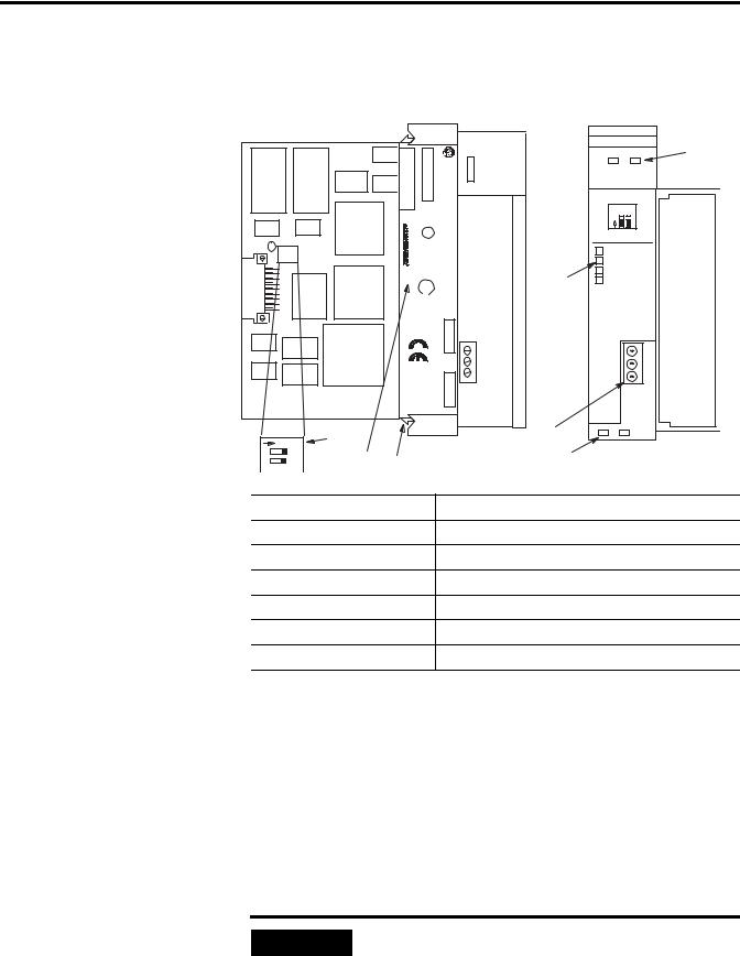
1-18 Overview
Hardware Features
Below are the scanner’s features. You can find LED information in Chapter 6, Troubleshooting.
|
|
|
.NOSERIAL |
|
CAT |
500SLC Remote |
SCANNER |
|
1 |
|
|
|
|
|
COMM FAULT |
||||||
|
|
|
) FAC |
SER |
ScannerI/O |
SW1 |
|
|
||
|
|
|
|
|
|
|
O |
1 2 |
|
|
|
|
CLASS |
|
|
|
|
N |
|
|
|
|
|
|
L |
|
|
/ 1 |
2 |
KBAUD |
|
|
|
|
CB,A,GROUPSI, |
A196.LOC.HAZFOR |
U |
|
|
|
|
|
|
|
|
.EQCONTINDLISTED.. |
|
|
ON |
ON |
57.6 |
|
||
|
|
|
|
|
|
|
|
|||
|
|
|
|
|
|
|
ON |
OFF |
115.2 |
|
|
|
|
|
|
|
2 |
OFF |
ON |
230.4 |
|
|
|
D, AND |
|
SA |
|
OFF |
OFF |
230.4 |
|
|
|
|
|
|
|
|
|||||
|
|
|
CURRENT |
|
|
|
|
|
||
|
|
2DIV. |
T3CCODE |
OPERATING TEMPERATURE) |
HOST :.FRN |
CONNECT ONE END OF |
|
|||
|
|
|
|
|
|
|
CABLE SHIELD TO CHASSIS |
|
||
|
|
|
|
|
|
|
MOUNTING BOLT. REFER T O |
|
||
|
|
|
|
|
REQUIREMENT: |
|
USER'S MANUAL. |
|
||
|
|
|
|
|
PLUG :.FRN |
LINE 1 |
|
|
|
|
|
|
|
|
|
|
|
SHIELD |
|
|
|
|
|
|
|
|
mA 600 |
|
LINE 2 |
|
|
|
|
|
MAKE |
|
|
|
|
|
|
|
|
|
|
.A.S.U IN |
|
|
@5VDC |
|
|
|
|
|
|
|
B |
|
|
|
|
|
|
|
|
|
|
|
|
|
|
|
1747±SN |
|
|
|
O N |
7 |
|
|
|
|
3 |
|
|
|
|
|
|
|
|
4 |
|
|
|
|
||
1 |
|
|
|
|
|
|
|
|
|
|
2 |
6 |
5 |
|
|
|
|
|
|
|
|
|
|
|
|
|
|
|
|
|
||
1. Status Led |
|
|
|
|
Displays normal communication and fault status |
|||||
2. Front Label |
|
|
|
|
Allows user to record configured baud rate |
|
||||
3. RIO Link Connector |
|
|
|
Allows for connections to RIO link devices |
|
|||||
4. Cable Tie Slots |
|
|
|
|
Secures communication wiring from module |
|
||||
5. Self-Locking Tabs |
|
|
|
|
Secures module in chassis slot |
|
|
|
||
6. Side Label (Nameplate) |
|
|
Provides module information |
|
|
|
|
|||
7. Baud Rate DIP Switch |
|
|
|
Allows user to set baud rate |
|
|
|
|
||
Baud Rate DIP Switch
The Baud Rate DIP switch selects the RIO link baud rate. The baud rates are:
•57.6 Kbaud
•115.2 Kbaud
•230.4 Kbaud
IMPORTANT |
For proper system operation, the baud rate of all |
|
devices on the RIO link must be the same. |
||
|
||
|
||
|
|
Publication 1747-UM013B-EN-P - January 2005

Overview 1-19
LEDs
Two LEDs allow you to monitor scanner and communication status.
FAULT LED - allows you to monitor scanner status. This LED is red. The FAULT LED’s normal state is off; therefore, it is off whenever the scanner is operating properly.
COMM LED - allows you to monitor communication with all configured devices. This LED is green and its normal state is on once the processor has entered Run mode. The LED is red if there is a communication problem. The COMM LED status information is valid only when the FAULT LED is off.
RIO Link Connector
This 3-pin male connector connects the scanner to the RIO link. The
Allen-Bradley repair part number is 1746-RT29.
Compatible Devices
Catalog Number |
Device |
Comments |
|
|
|
1785-LT/x(1) (2) |
PLC- 5/15 (in adapter mode) |
- |
1785-LT2(1)(2) |
PLC- 5/25 (in adapter mode) |
- |
1785-LT3(1)(2) |
PLC- 5/12 (in adapter mode) |
- |
1785-L30x(1)(2) |
PLC- 5/30 (in adapter mode) |
- |
1785-L40x(1)(2) |
PLC- 5/40 (in adapter mode) |
- |
1785-L60x(1)(2) |
PLC- 5/60 (in adapter mode) |
- |
1771-ASC |
Remote I/O Adapter Module |
- |
|
|
|
1771-ASB(3) (4) |
Remote I/O Adapter Module |
- |
1771-AM1(1) |
1-Slot I/O Chassis W/Integral Power Supply and |
- |
|
Adapter |
|
|
|
|
1771-AM2(1) |
2-Slot I/O Chassis W/Integral Power Supply and |
- |
|
Adapter |
|
|
|
|
1784-F30D(1) |
Plant Floor Terminal Remote I/O Expansion |
- |
|
Module |
|
|
|
|
1771-RIO |
Remote I/O Interface Module |
- |
|
|
|
Publication 1747-UM013B-EN-P - January 2005

1-20 Overview
Catalog Number |
Device |
Comments |
|
|
|
1771-JAB(1) |
Single Point I/O Adapter Module Single Point I/O |
- |
|
Adapter Module |
|
|
|
|
1771-DCM |
Direct Communication Module |
- |
|
|
|
1778-ASB(1) |
Remote I/O Adapter Module |
- |
1747-DCM(1) |
Direct Communication Module |
- |
2706-xxxx(1)(5) |
DL40 Dataliner |
- |
2705-xxx(1) |
RediPANEL |
Requires half logical rack configuration if you want to use |
|
|
stored messages.Requires half logical rack configuration if |
|
|
you want to use stored messages. |
|
|
|
2711-xx(1) |
PanelView Terminal |
You can address PanelView Terminals as up to four full |
|
|
logical racks of discrete I/O. You can also assign partial |
|
|
logical racks.You can address PanelView Terminals as up to |
|
|
four full logical racks of discrete I/O. You can also assign |
|
|
partial logical racks. |
|
|
|
1336-G2(1) |
Remote I/O Adapter for 1336 AC Industrial |
- |
|
Drives |
|
|
|
|
1395-NA(1) |
Remote I/O Adapter for 1395 DC Industrial |
- |
|
Drives |
|
|
|
|
1791-xxx |
Block I/O Products |
The adapter is built into the block. |
|
|
|
1747-ASB(1) |
SLC 500 Remote I/O Adapter Module |
- |
1794-ASB |
Flex I/O 24VDC Remote I/O Adapter |
- |
|
|
|
(1)Extended node capability
(2)In adapter mode
(3)Series A, B, and C
(4)Extended node capability for Series B and C
(5)Must be Catalog Number 2706-ExxxxxB1
Publication 1747-UM013B-EN-P - January 2005

Chapter 2
Required Tools and
Equipment
Quick Start for Experienced Users
This chapter helps you to get started using the RIO Scanner. We base the procedures here on the assumption that you have a basic understanding of SLC 500 products.
You must:
•understand electronic process control
•be able to interpret the ladder logic instructions for generating the electronic signals that control your application
Because it is a start-up guide for experienced users, this chapter does not contain detailed explanations about the procedures listed. It does, however, reference other chapters in this book where you can get more detailed information. It also references other documentation that may be helpful if you are unfamiliar with programming techniques or system installation requirements.
If you have any questions, or are unfamiliar with the terms used or concepts presented in the procedural steps, always read the referenced chapters and other recommended documentation before trying to apply the information.
This chapter:
•tells you what tools and equipment you need
•lists preliminary considerations
•describes when to address, configure and program the module
•explains how to install and wire the module
•discusses system power-up procedures
Have the following tools and equipment ready:
•medium blade screwdriver
•programming equipment
•termination kit (package of resistors and ring lug included with the scanner)
•approximately 15 inches of #20 AWG for grounding the drain shield to the SLC chassis (for Series A retrofits)
•an adequate length of RIO communication cable (Belden 9463) for your specific application
Publication 1747-UM013B-EN-P - January 2005

2-2 Quick Start for Experienced Users
Procedures
1.Check the contents of the shipping box.
Unpack the module making sure that the contents include:
•RIO Scanner (Catalog Number 1747 SN)
•termination kit
If the contents are incomplete, call your local Allen-Bradley representative for assistance.
2.Ensure you chassis supports placement of the 1747-SN module.
Review the power requirements of your system to see that your chassis supports placement of the scanner module. The scanner consumes 600 mA @ 5VDC.
For modular style systems, calculate the total load on the system power supply using the procedure described in the SLC 500 Modular Hardware Style User Manual, Publication 1747-UM011.
See Chapter 3, Installation and Wiring and Appendix A Specifications in this manual.
3.Configure the module using the DIP switches.
Set the DIP switches (located on the printed circuit board) to the desired baud rate. Note that all RIO devices must be configured for the same baud rate.
Baud Rate |
DIP Switch Position |
|
|
|
|
|
Switch 1 |
Switch 2 |
|
|
|
57.6K baud |
on |
on |
|
|
|
115.2K baud |
on |
off |
|
|
|
230.4K baud |
off |
on |
|
|
|
230.4K baud |
off |
off |
|
|
|
See Chapter 3, Installation and Wiring.
4. Insert the 1747-SN module into the chassis.
Publication 1747-UM013B-EN-P - January 2005
Loading...