


1756-RIO
Table of contents
 Loading...
User Manual
ControlLogix Remote I/O Communication Module
Catalog Number
1756-RIO
Important User Information
IMPORTANT
Solid-state equipment has operational characteristics differing from those of electromechanical equipment. Safety
Guidelines for the Application, Installation and Maintenance of Solid State Controls (publication SGI-1.1
your local Rockwell Automation sales office or online at http://www.rockwellautomation.com/literature/
important differences between solid-state equipment and hard-wired electromechanical devices. Because of this difference,
and also because of the wide variety of uses for solid-state equipment, all persons responsible for applying this equipment
must satisfy themselves that each intended application of this equipment is acceptable.
In no event will Rockwell Automation, Inc. be responsible or liable for indirect or consequential damages resulting from
the use or application of this equipment.
The examples and diagrams in this manual are included solely for illustrative purposes. Because of the many variables and
requirements associated with any particular installation, Rockwell Automation, Inc. cannot assume responsibility or
liability for actual use based on the examples and diagrams.
No patent liability is assumed by Rockwell Automation, Inc. with respect to use of information, circuits, equipment, or
software described in this manual.
Reproduction of the contents of this manual, in whole or in part, without written permission of Rockwell Automation,
Inc., is prohibited.
Throughout this manual, when necessary, we use notes to make you aware of safety considerations.
WARNING: Identifies information about practices or circumstances that can cause an explosion in a hazardous
environment, which may lead to personal injury or death, property damage, or economic loss.
available from
) describes some
ATTENTION: Identifies information about practices or circumstances that can lead to personal injury or death,
property damage, or economic loss. Attentions help you identify a hazard, avoid a hazard, and recognize the
consequence
SHOCK HAZARD: Labels may be on or inside the equipment, for example, a drive or motor, to alert people that
dangerous voltage may be present.
BURN HAZARD: Labels may be on or inside the equipment, for example, a drive or motor, to alert people that
surfaces may reach dangerous temperatures.
Identifies information that is critical for successful application and understanding of the product.
Allen-Bradley, Rockwell Software, Rockwell Automation, RSLogix 5000, ControlLogix, ProcessLogix, RSLinx, ControlFlash, PLC-5, PLC-3, SLC, and TechConnect are trademarks of Rockwell Automation, Inc.
Trademarks not belonging to Rockwell Automation are property of their respective companies.
Summary of Changes
This manual contains new and updated information. This manual includes the
addition of the 1756-RIO/B module. Changes throughout this revision are
marked by change bars, as shown to the right of this paragraph.
New and Updated Information
This table contains the changes made to this revision.
Topic Page
1756-RIO module front diagram 13
Publication 1756-UM534B-EN-P - November 2010 3

Summary of Changes
Notes:
4 4Publication 1756-UM534B-EN-P - November 2010

Table of Contents
Preface
The 1756-RIO Module-Getting
Started
Introduction . . . . . . . . . . . . . . . . . . . . . . . . . . . . . . . . . . . . . . . . . . . . . . . 9
Who Should Use This Manual. . . . . . . . . . . . . . . . . . . . . . . . . . . . . . . . 10
Information Found in This Manual . . . . . . . . . . . . . . . . . . . . . . . . . . . 10
Additional Resources . . . . . . . . . . . . . . . . . . . . . . . . . . . . . . . . . . . . . . . 10
Chapter 1
Introduction . . . . . . . . . . . . . . . . . . . . . . . . . . . . . . . . . . . . . . . . . . . . . . 11
1756-RIO Module Components . . . . . . . . . . . . . . . . . . . . . . . . . . . . . . 13
1756-RIO Module Requirements . . . . . . . . . . . . . . . . . . . . . . . . . . . . . 15
The 1756-RIO Modes . . . . . . . . . . . . . . . . . . . . . . . . . . . . . . . . . . . . . . 15
Prepare the Module . . . . . . . . . . . . . . . . . . . . . . . . . . . . . . . . . . . . . . . . 16
Install the Software. . . . . . . . . . . . . . . . . . . . . . . . . . . . . . . . . . . . . . . . . 19
Install the Add-on Profile . . . . . . . . . . . . . . . . . . . . . . . . . . . . . . . . . . . 19
Create the RSLogix 5000 Project. . . . . . . . . . . . . . . . . . . . . . . . . . . . . . 22
Configure the Controller . . . . . . . . . . . . . . . . . . . . . . . . . . . . . . . . . 23
Add the 1756-RIO Module . . . . . . . . . . . . . . . . . . . . . . . . . . . . . . . 24
Enter the RPI. . . . . . . . . . . . . . . . . . . . . . . . . . . . . . . . . . . . . . . . . . 27
Set Communication Path and Download to the Controller in the
RSLogix 5000 Project. . . . . . . . . . . . . . . . . . . . . . . . . . . . . . . . . . . . . . . 30
Launch the Configuration Tool and Select the Module Mode . . . . . . 30
Launch the 1756-RIO Configuration Tool. . . . . . . . . . . . . . . . . . . 31
Configure Scanner Mode
Configure Adapter Mode
Chapter 2
Introduction . . . . . . . . . . . . . . . . . . . . . . . . . . . . . . . . . . . . . . . . . . . . . . 37
Configure Scanner Summary . . . . . . . . . . . . . . . . . . . . . . . . . . . . . . . . . 38
Set the Baud Rate . . . . . . . . . . . . . . . . . . . . . . . . . . . . . . . . . . . . . . . . . . 39
Autoconfigure Racks . . . . . . . . . . . . . . . . . . . . . . . . . . . . . . . . . . . . . . . 40
Manually Configure Racks . . . . . . . . . . . . . . . . . . . . . . . . . . . . . . . . . . . 43
Matching Configuration Tool Settings with Module Settings . . . . 44
Resize a Rack . . . . . . . . . . . . . . . . . . . . . . . . . . . . . . . . . . . . . . . . . . 45
Delete a Rack . . . . . . . . . . . . . . . . . . . . . . . . . . . . . . . . . . . . . . . . . . 46
Configure Block Transfer Modules. . . . . . . . . . . . . . . . . . . . . . . . . . . . 46
Map I/O Data . . . . . . . . . . . . . . . . . . . . . . . . . . . . . . . . . . . . . . . . . . . . 51
Automatic Mapping. . . . . . . . . . . . . . . . . . . . . . . . . . . . . . . . . . . . . 53
Manually Map Discrete (rack) Data . . . . . . . . . . . . . . . . . . . . . . . . 53
Manually Map Block Transfer Data . . . . . . . . . . . . . . . . . . . . . . . . 55
Re-Map Command . . . . . . . . . . . . . . . . . . . . . . . . . . . . . . . . . . . . . 56
Clear Mappings . . . . . . . . . . . . . . . . . . . . . . . . . . . . . . . . . . . . . . . . 57
Chapter 3
Introduction . . . . . . . . . . . . . . . . . . . . . . . . . . . . . . . . . . . . . . . . . . . . . . 61
Configure Adapter Summary. . . . . . . . . . . . . . . . . . . . . . . . . . . . . . . . . 62
Set the Baud Rate . . . . . . . . . . . . . . . . . . . . . . . . . . . . . . . . . . . . . . . . . . 63
Autoconfigure Racks . . . . . . . . . . . . . . . . . . . . . . . . . . . . . . . . . . . . . . . 64
Perform the AutoConfiguration . . . . . . . . . . . . . . . . . . . . . . . . . . 65
5Publication 1756-UM534B-EN-P - November 2010 5

Table of Contents
Link Module Configuration with
RSLogix 5000 Project
Active Versus Monitored Racks on the Network . . . . . . . . . . . . . 67
Manually Configure Racks . . . . . . . . . . . . . . . . . . . . . . . . . . . . . . . . . . . 69
Resizing Racks . . . . . . . . . . . . . . . . . . . . . . . . . . . . . . . . . . . . . . . . . 70
Delete Racks. . . . . . . . . . . . . . . . . . . . . . . . . . . . . . . . . . . . . . . . . . . 71
Configure Block-transfer Modules . . . . . . . . . . . . . . . . . . . . . . . . . . . . 72
Map I/O Data . . . . . . . . . . . . . . . . . . . . . . . . . . . . . . . . . . . . . . . . . . . . 76
Automatic Mapping. . . . . . . . . . . . . . . . . . . . . . . . . . . . . . . . . . . . . 76
Manually Map Discrete Data. . . . . . . . . . . . . . . . . . . . . . . . . . . . . . 77
Re-Map Command . . . . . . . . . . . . . . . . . . . . . . . . . . . . . . . . . . . . . 79
Clear Mappings . . . . . . . . . . . . . . . . . . . . . . . . . . . . . . . . . . . . . . . . 80
Chapter 4
Introduction . . . . . . . . . . . . . . . . . . . . . . . . . . . . . . . . . . . . . . . . . . . . . . 83
Commission Summary. . . . . . . . . . . . . . . . . . . . . . . . . . . . . . . . . . . . . . 83
Aliases . . . . . . . . . . . . . . . . . . . . . . . . . . . . . . . . . . . . . . . . . . . . . . . . . . . 84
Export Aliases in Scanner Mode. . . . . . . . . . . . . . . . . . . . . . . . . . . 85
Export Aliases in Adapter Mode. . . . . . . . . . . . . . . . . . . . . . . . . . . 86
Use Monitor Mode to Upgrade an Existing System to
a ControlLogix System . . . . . . . . . . . . . . . . . . . . . . . . . . . . . . . . . . 87
Manage Configurations . . . . . . . . . . . . . . . . . . . . . . . . . . . . . . . . . . . . . 91
Download and Upload Configurations. . . . . . . . . . . . . . . . . . . . . . 91
Save Configurations to Disk . . . . . . . . . . . . . . . . . . . . . . . . . . . . . . 93
Archive Configurations . . . . . . . . . . . . . . . . . . . . . . . . . . . . . . . . . . 94
Monitor Remote I/O
Chapter 5
Introduction . . . . . . . . . . . . . . . . . . . . . . . . . . . . . . . . . . . . . . . . . . . . . . 97
Commission Summary. . . . . . . . . . . . . . . . . . . . . . . . . . . . . . . . . . . . . . 98
Scan Mode and Monitor Mode . . . . . . . . . . . . . . . . . . . . . . . . . . . . . . . 99
Scan Remote I/O in Scanner Mode . . . . . . . . . . . . . . . . . . . . . . . . 99
Monitor Remote I/O in Adapter Mode . . . . . . . . . . . . . . . . . . . . 100
Monitor Discrete Inputs and Outputs . . . . . . . . . . . . . . . . . . . . . . . . 101
Monitor Discrete Inputs in Scanner Mode. . . . . . . . . . . . . . . . . . 101
Monitor Discrete Outputs in Scanner Mode . . . . . . . . . . . . . . . . 104
Monitor Discrete Inputs in Adapter Mode. . . . . . . . . . . . . . . . . . 106
Monitor Discrete Outputs in Adapter Mode . . . . . . . . . . . . . . . . 107
Monitor Discrete Active Inputs in Adapter Mode. . . . . . . . . . . . 108
Monitor Block Transfers . . . . . . . . . . . . . . . . . . . . . . . . . . . . . . . . . . . 108
Monitor Block Transfers in Scanner Mode . . . . . . . . . . . . . . . . . 109
Monitor Block Transfers in Adapter Mode . . . . . . . . . . . . . . . . . 112
Export Scanner Configurations. . . . . . . . . . . . . . . . . . . . . . . . . . . . . . 115
Monitor Mode . . . . . . . . . . . . . . . . . . . . . . . . . . . . . . . . . . . . . . . . 116
Other Diagnostics . . . . . . . . . . . . . . . . . . . . . . . . . . . . . . . . . . . . . . . . 117
Monitor Diagnostic Counters in Scanner Mode . . . . . . . . . . . . . 117
Monitor Diagnostic Counters in Adapter Mode . . . . . . . . . . . . . 120
Module Scanner Log . . . . . . . . . . . . . . . . . . . . . . . . . . . . . . . . . . . 121
6 Publication 1756-UM534B-EN-P - November 2010

Scanner Mode I/O Map
Adapter Mode I/O Map
Table of Contents
Clear Diagnostics . . . . . . . . . . . . . . . . . . . . . . . . . . . . . . . . . . . . . . 124
Fatal Errors . . . . . . . . . . . . . . . . . . . . . . . . . . . . . . . . . . . . . . . . . . 125
Appendix A
Discrete Input Data . . . . . . . . . . . . . . . . . . . . . . . . . . . . . . . . . . . . 129
Discrete Output Data . . . . . . . . . . . . . . . . . . . . . . . . . . . . . . . . . . 131
Block Transfer Input . . . . . . . . . . . . . . . . . . . . . . . . . . . . . . . . . . . 134
Block Transfer Output . . . . . . . . . . . . . . . . . . . . . . . . . . . . . . . . . 136
Appendix B
Discrete Data . . . . . . . . . . . . . . . . . . . . . . . . . . . . . . . . . . . . . . . . . . . . 141
Discrete Input Data . . . . . . . . . . . . . . . . . . . . . . . . . . . . . . . . . . . . 141
Discrete Output Data on Monitored or Active Racks. . . . . . . . . 144
Block Transfer Modules . . . . . . . . . . . . . . . . . . . . . . . . . . . . . . . . . . . 148
Block Transfer Read Data on Monitored or Active Racks . . . . . 148
Block Transfer Write Data on Monitored or Active Racks. . . . . 150
Block Transfer Module Templates
Troubleshooting Display and
Status Indicators
Quick Start
Appendix C
Block Transfer Template Records . . . . . . . . . . . . . . . . . . . . . . . . 154
Block Transfer Lengths . . . . . . . . . . . . . . . . . . . . . . . . . . . . . . . . . 155
Parameters . . . . . . . . . . . . . . . . . . . . . . . . . . . . . . . . . . . . . . . . . . . 156
Parameter Examples . . . . . . . . . . . . . . . . . . . . . . . . . . . . . . . . . . . 158
Aliases. . . . . . . . . . . . . . . . . . . . . . . . . . . . . . . . . . . . . . . . . . . . . . . 159
Appendix D
Alphanumeric Display . . . . . . . . . . . . . . . . . . . . . . . . . . . . . . . . . . . . . 161
Status Indicators. . . . . . . . . . . . . . . . . . . . . . . . . . . . . . . . . . . . . . . . . . 162
RIO Status Indicator – Remote Devices Status . . . . . . . . . . . . . . 162
CLX Status Indicator – ControlBus Status. . . . . . . . . . . . . . . . . . 163
OK Status Indicator – Module Health . . . . . . . . . . . . . . . . . . . . 164
The Debug Log . . . . . . . . . . . . . . . . . . . . . . . . . . . . . . . . . . . . . . . 164
Fatal Errors . . . . . . . . . . . . . . . . . . . . . . . . . . . . . . . . . . . . . . . . . . 164
Watchdog and Jabber Inhibit . . . . . . . . . . . . . . . . . . . . . . . . . . . . 165
Updating the Firmware . . . . . . . . . . . . . . . . . . . . . . . . . . . . . . . . . 165
Appendix E
ControlLogix System Quick Start . . . . . . . . . . . . . . . . . . . . . . . . . . . . 167
Index
Publication 1756-UM534B-EN-P - November 2010 7

Table of Contents
Notes:
8 Publication 1756-UM534B-EN-P - November 2010

Preface
Introduction
This manual describes how to configure and troubleshoot your Logix Remote
I/O (RIO) Communication Module.
The 1756-RIO module:
• runs in a ControlLogix environment.
• allows upgrade from PLC-5, PLC-3, or SLC systems to a ControlLogix
system with a minimum of downtime and startup time.
• uses integer data.
• does not require MSG instructions. All data is scheduled.
• offloads block transfer execution to reduce processing burden on the
processor.
This publication explains how and why you would use a 1756-RIO module.
The module is used in two modes, scanner and adapter mode.
In scanner mode, the 1756-RIO module enables communication and data
transfer between a ControlLogix controller and devices on a Remote I/O
network. The module continuously scans adapters on the remote network. The
module transfers discrete and block transfer data.
In adapter mode, the module performs two functions simultaneously. First, it
emulates one or more racks of I/O to a scanner, exchanging data with that
scanner. Second, it monitors other remote I/O racks on the same Remote I/O
network.
It can be used to upgrade an existing PLC-5, PLC-3, or SLC system to a
ControlLogix system.
The advantages of using the 1756-RIO module to upgrade your system
include:
• allowing the user to leave the existing Remote I/O network in place,
alleviating the time and/or expense of replacing the I/O and field
wiring, or the process of testing out field wiring.
• allowing the new application to be tested before you switch over, so that
it works just like the old one.
• allowing you to switch back to the old application in minutes, should
you run into problems.
For installation information, see the Remote I/O (RIO) Module Installation
Instructions, publication 1756-IN610
.
9Publication 1756-UM534B-EN-P - November 2010 9

Preface
Who Should Use This Manual
Information Found in This Manual
We assume you understand remote I/O (RIO) modules and the host
controller system (ControlLogix).
This manual is intended for individuals who use DHRIO, PLC-5, PLC-3, SLC,
or ControlLogix systems, such as:
• software engineers.
• control engineers.
• application engineers.
• instrumentation technicians.
This manual is broken into five parts:
• General module information and features -
• Scanner mode functionality -
• Adapter mode functionality -
• Linking module configuration with an RSLogix 5000 project Monitoring remote I/O -
Chapter 2
Chapter 3
Chapter 5
Chapter 1
, and
Appendices A
, and
Appendices B
and
Appendix D
and
and
C
C
Chapter 4
Additional Resources
These documents contain additional information concerning related Rockwell
Automation products.
Resource Description
Remote I/O (RIO) Module Installation
Instructions,
publication 1756-IN610
Industrial Automation Wiring and Grounding
Guidelines, publication 1770-4.1
Product Certifications website,
http://ab.com
You can view or download publications at
http://literature.rockwellautomation.com
documentation, contact your local Rockwell Automation distributor or sales
representative.
Provides details on how to install the 1756RIO module
Provides general guidelines for installing a
Rockwell Automation industrial system
Provides declarations of conformity,
certificates, and other certification details
. To order paper copies of technical
10 Publication 1756-UM534B-EN-P - November 2010
Chapter
The 1756-RIO Module-Getting Started
1
Introduction
This document is a user’s guide for the 1756-RIO module. The module lets
Rockwell Automation ControlLogix controllers communicate with remote I/
O over the backplane or over a remote network. This chapter describes the
ControlLogix 1756-RIO module and how it links a ControlLogix controller to
the Universal Remote I/O network.
This chapter also describes the module’s physical features, software
requirements, software and add-on profile installation instructions, and
RSLogix 5000 project setup.
Topic Page
1756-RIO Module Components
1756-RIO Module Requirements
Prepare the Module
Install the Software
Install the Add-on Profile
Create the RSLogix 5000 Project
Launch the Configuration Tool and Select the Module Mode
The 1756-RIO module:
13
15
16
19
19
22
30
supports native RIO 16-bit words for data, control, and status bits.
acts as a scanner on a Remote I/O network.
acts as an adapter that exchanges data on a Remote I/O network.
supports discrete data and block transfer data in either mode.
supports up to 10 produced/consumed data connections (along the
backplane between the ControlLogix controller and the 1756-RIO
module) with 248 words of integer input and 248 words of integer
output for each connection.
uses produced/consumed connections using a 1756-RIO add-on profile
in RSLogix 5000 programming software.
supports requested packet intervals (RPIs) from 2…750 ms. All
connections use one set RPI.
maps all discrete and block transfer data into produced/consumed
connections.
monitors existing I/O in adapter mode (Monitor mode). It can report
all existing inputs and outputs, discrete and block transfer module data
to the ControlLogix controller.
11Publication 1756-UM534B-EN-P - November 2010 11
Chapter 1 The 1756-RIO Module-Getting Started
The following modules are supported by the 1756-RIO module.
Supported Modules
I/O Family Cat. No.
1746 SLC 1746-N14
1746-N18
1771 PLC-5 1771-DE 1771-NIV
1771-IFE-16CH (in single-ended 16
Channel configuration)
1746-N04V
1746-NT4
1771-NOC-noBTR
1771-IFE-8CH (in differential 8
Channel configuration)
1771-IL-Alarms 1771-NOV-noBTR
1771-IL 1771-NOV
1771-IR 1771-NR
1771-IXE 1771-OFE-diag
1771-NIV-Alarms 1771-OFE
1794 FLEX 1794-IE4XOE2 1794-OE4
1794-IE8
1771-NOC
See Appendix C for additional information.
12 Publication 1756-UM534B-EN-P - November 2010
The 1756-RIO Module-Getting Started Chapter 1
RIO CLX OK
1
2
44777
1
2
3
4
43161
Note that the 3-pin connector
has been changed.
1
2
RIO CLX OK
43161A
44777A
1
2
3
4
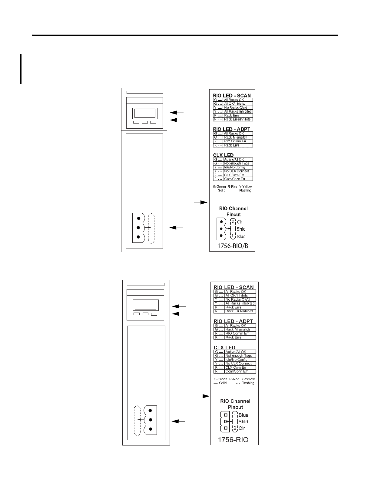
1756-RIO Module Components
The 1756-RIO module components include a 4-character display, status
indicators, an RTB connection, and an inside-door label.
1756-RIO/B Module
Publication 1756-UM534B-EN-P - November 2010 13
1756-RIO/A Module
Chapter 1 The 1756-RIO Module-Getting Started
Item Description
1 4-character scrolling display
2 Three status indicators
RIO indicates the status of the network
CLX indicates the status of the connection to the controller
OK indicates the module’s own internal state
3 3-pin connector (blue hose) that connects to the remote devices
This is also known as the removable terminal block (RTB).
4 Inside-door label with error codes
14 Publication 1756-UM534B-EN-P - November 2010

The 1756-RIO Module-Getting Started Chapter 1
1756-RIO Module Requirements
The 1756-RIO Modes
The requirements for the module to operate include the installation of:
RSLogix 5000 programming software, version 17 or later, and the
associated controller firmware.
RSLinx software, version 2.54 or later, with an activation. Use RSLinx
Gateway or RSLinx Professional software. Do not use RSLinx Lite
software.
the 1756-RIO module add-on profile from the CD provided with the
module.
the 1756-RIO module installed in a 1756-ControlLogix chassis.
The 1756-RIO module can be used in various capacities depending on the
user’s needs. First, decide which mode you want the 1756-RIO module to use.
In most cases, the module is used in scanner mode to scan and control remote
I/O data on a network.
In adapter mode, the 1756-RIO module can perform two functions
simultaneously. First, the module can emulate one or more racks of I/O to a
scanner, exchanging data with that scanner (for example, a PLC-5, PLC-3, or
SLC). It can exchange data with the scanner as discrete data, or via block
transfers.
Second, the 1756-RIO module can act as a ‘shadow,’ referred to as Monitor
mode, to monitor racks on a remote network. The module listens to the
remote I/O and provides all inputs and outputs from the existing scanner to
the ControlLogix controller. Users can then run their converted logic against
those inputs, generate temporary outputs, and compare the existing outputs
with outputs generated by the new logic.
Publication 1756-UM534B-EN-P - November 2010 15

Chapter 1 The 1756-RIO Module-Getting Started
Prepare the Module
The following list summarizes the initial steps needed to prepare the 1756RIO module before setting up the remote network. These steps will be
discussed in detail in this chapter.
You can have only one scanner per RIO network. Remove any other scanners
on the RIO network before continuing. The RIO module ships in scanner
mode. You can adjust the instructions to fit the mode that matches your needs.
1. Install RSLinx software, version 2.54 or later, with an activation. Use
RSLinx Gateway or RSLinx Professional software. Do not use RSLinx
Lite software.
2. Install RSLogix 5000 programming software, version 17 or later, and the
associated controller firmware.
3. Install the 1756-RIO module in the 1756-ControlLogix chassis.
See publication 1756-IN610
Install the 1756-RIO module’s add-on profile found on the installation
CD shipped with the module, or download it from
support.rockwellautomation.com/controlflash/LogixProfiler.asp
RSLinx software and RSLogix 5000 programming software must be
installed before the add-on profile.
.
http://
.
See page 19
4. Create a project in RSLogix 5000 programming software.
5. Add a 1756 controller to your project.
See page 23
6. Add a 1756-RIO module to the project by right-clicking on the chassis
in the Controller Organizer and selecting New Module.
The Select Module dialog box appears.
7. Expand the Communications heading and select the 1756-RIO module.
Click OK.
page 24
See
8. Select the General tab on the Module Properties dialog box to set the
module properties.
.
.
.
16 Publication 1756-UM534B-EN-P - November 2010

The 1756-RIO Module-Getting Started Chapter 1
9. Enter the module name and slot number.
page 24
See
.
10. Click the Change button in the Module Definition section. Select your
desired mode, scanner or adapter.
The module ships in scanner mode. Note the number of input/output
tags. If this number is not the same after you map your data with the
configuration tool, you will have to return to this screen and change
them to match your configuration. You can specify independently the
number of input and output tags within the range of 1…10. Each tag
you create will create a block of 248 integers. For example, a value of 2
will create 2x248, or 498 integers.
11. When done, click OK on the Module Definition dialog box.
See page 25.
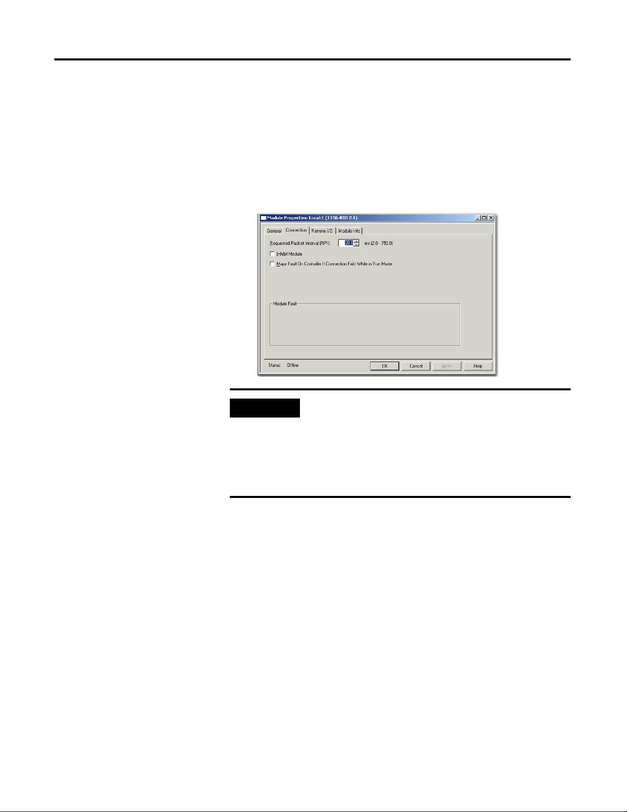
12. Select the Connection tab on the Module Properties dialog box.
13. Set the Requested Packet Interval (RPI).
See page 27.
14. Click on the Remote I/O tab, name the RIO file, and click the OK
button.
15. Choose Yes on the Create dialog box.
page 31
See
.
This will close the Module Properties dialog box. You will need to
double-click on the 1756-RIO module in the controller organizer to reopen the Module Properties dialog box.
16. Click on the Configure Remote I/O Devices button on the Module
Properties dialog box to launch the configuration tool.
17. In the configuration tool, if needed, under the Tools menu, select Set
1756-RIO Module Scanner/Adapter Mode menu to match the RIO
module functionality to match your application, Scanner or Adapter.
See
pages 33
.
18. Configure the RIO module to match your application. In scanner mode,
add the desired racks to scan, and any block transfer modules. In adapter
mode, configure the desired racks to be emulated, or monitored, and
add any block transfer modules. Map all entries, either manually, or by
using the Automap command.
pages 51
See
Publication 1756-UM534B-EN-P - November 2010 17
and 76.

Chapter 1 The 1756-RIO Module-Getting Started
19. Download the configuration to the module. From the configuration
tool’s Configure menu, select Download Configuration. Set the
communication path when prompted.
See page
91
.
20. Save the project.
21. Go online in the RSLogix 5000 project and download the configuration
to the controller.
30
.
and 3 for in-depth information on setting module modes and
See
Chapters 2
See page
configuration.
18 Publication 1756-UM534B-EN-P - November 2010

The 1756-RIO Module-Getting Started Chapter 1
IMPORTANT
Install the Software
Install the Add-on Profile
Begin by installing the RSLinx software, version 2.54 or later, with an
activation, on your computer. You must use RSLinx Gateway or RSLinx
Professional software. Do not use RSLinx Lite software.
Then, install RSLogix 5000 programming software, version 17 or later, and the
associated controller firmware.
Install the 1756-RIO module in the 1756-ControlLogix chassis.
See publication 1756-IN610
Installing the add-on profile also installs the software configuration tool. The
add-on profile and the configuration tool (56RioCfg) are on the CD that ships
with your module.
Once loaded onto your computer, the configuration tool is accessible within
the RSLogix 5000 add-on profile. The configuration tool contains two separate
programs; one for scanner mode, 56RioCfgScan; and one for adapter mode,
56RioCfgAdpt. The program that launches depends on which mode you
select.
.
The 1756-RIO module requires RSLogix 5000 programming
software, version 17, or later. The add-on profile does not work
with previous versions of RSLogix 5000 programming software.
With the configuration tool, you can:
• change modes.
• set the baud rate.
• autoconfigure racks from an attached Remote I/O network.
• manually add and configure racks.
• add and configure block transfer modules.
• map I/O data to the ControlLogix controller produced/consumed
connections.
• save and load configuration files.
• download and upload configurations.
• archive projects.
• monitor diagnostics, rack status, discrete data, and block transfers.
Publication 1756-UM534B-EN-P - November 2010 19
Chapter 1 The 1756-RIO Module-Getting Started
ATTENTION
To install the add-on profile along with the configuration tool, follow these
steps.
1. Make sure any instances of RSLogix 5000 programming software is shut
down before beginning.
2. Insert the CD that was shipped with your module into your computer.
If you get a message about DTL32.DLL when installing or
running the programs on the configuration CD, it indicates
problems with the RSLinx software installation. Confirm that
you have the correct version of RSLinx software. RSLinx Lite
software cannot be used.
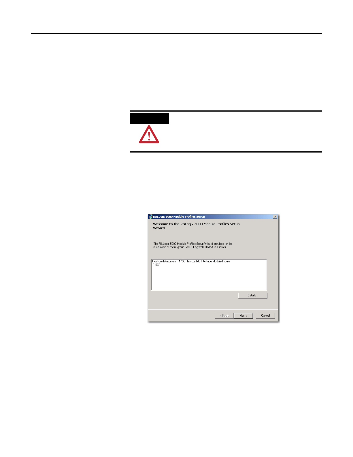
3. Open the folder 1756-RIO Configuration Tool Setup. Run the
MPSetup.exe program.
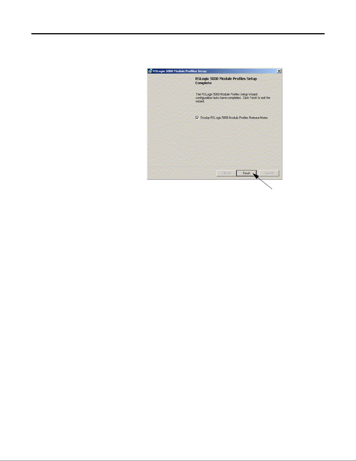
The RSLogix 5000 Module Profiles Setup Wizard launches.
4. Follow the prompts to complete the installation. Click Next. Accept the
License Agreement, install the profile, and begin.
20 Publication 1756-UM534B-EN-P - November 2010
The 1756-RIO Module-Getting Started Chapter 1
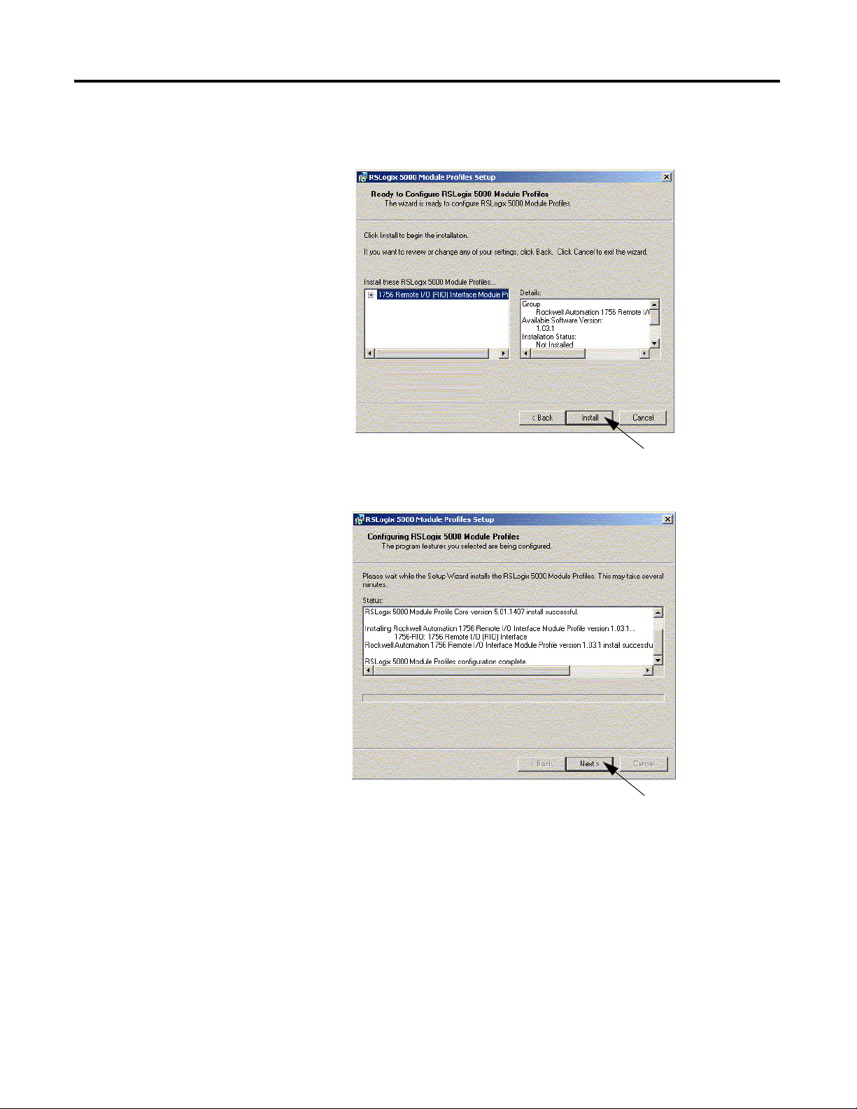
5. On the Module Profiles Setup dialog box, click Install to configure
RSLogix 5000 Module Profiles.
6. Click Next.
Publication 1756-UM534B-EN-P - November 2010 21
Chapter 1 The 1756-RIO Module-Getting Started
7. Click Finish.
Create the RSLogix 5000 Project
Once the add-on profile is installed, you are ready to create the RSLogix 5000
project. In this section, you will:
start a new project.
configure the controller in the project.
add the 1756-RIO module to the project.
enter the requested pack interval (RPI).
22 Publication 1756-UM534B-EN-P - November 2010
The 1756-RIO Module-Getting Started Chapter 1
Configure the Controller
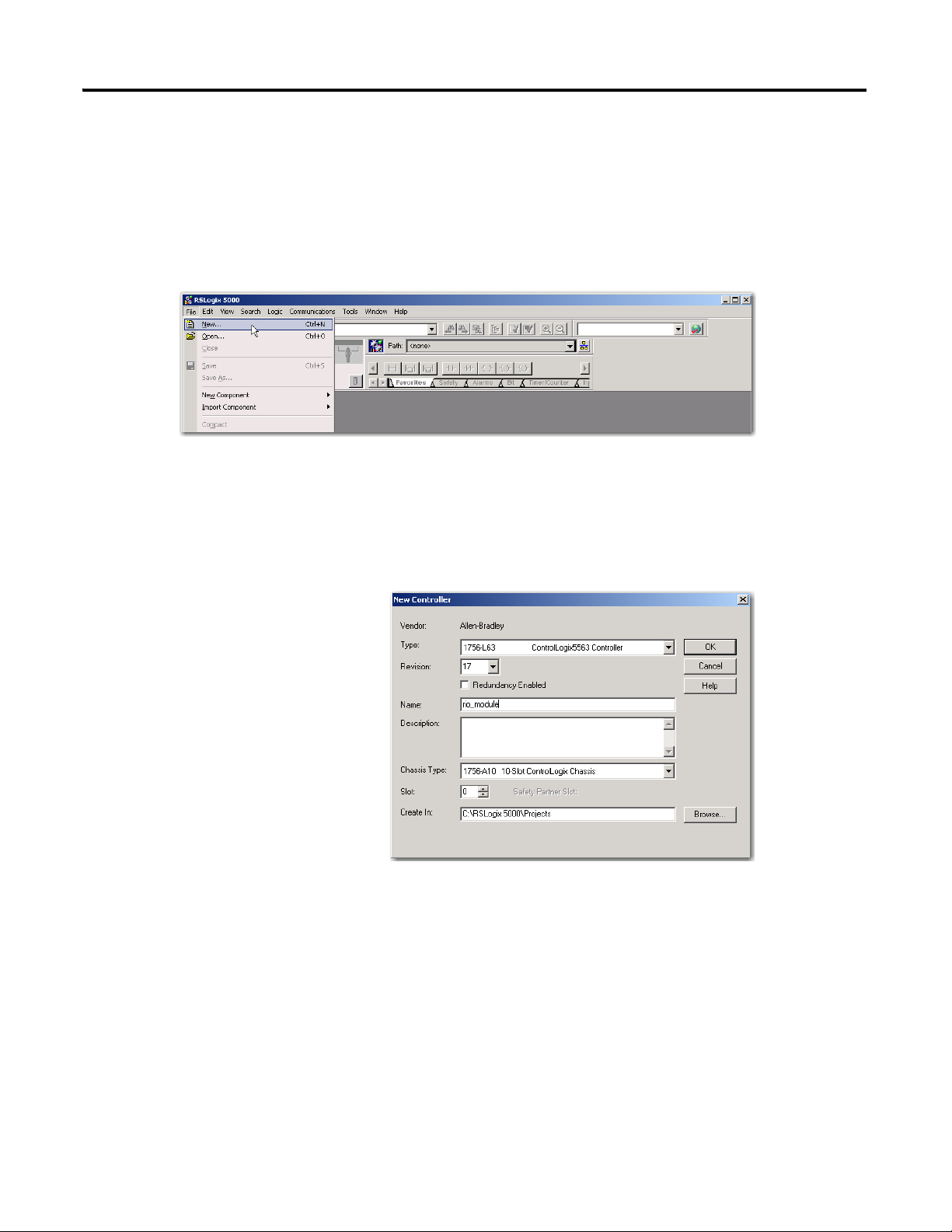
1. Launch RSLogix 5000 programming software, if it is not opened.
2. In the RSLogix 5000 programming software Controller Organizer, from
the File menu, choose New.
3. On the New Controller dialog box, select a 1756 controller, the Revision
number, Name, Chassis Type, and Slot number. The 1756-RIO module
can only be used in RSLogix 5000 programming software, version 17, or
later.
4. Click OK.
Publication 1756-UM534B-EN-P - November 2010 23
Chapter 1 The 1756-RIO Module-Getting Started
IMPORTANT
Add the 1756-RIO Module
You must be offline to add the module to the I/O configuration
in the RSLogix 5000 project.
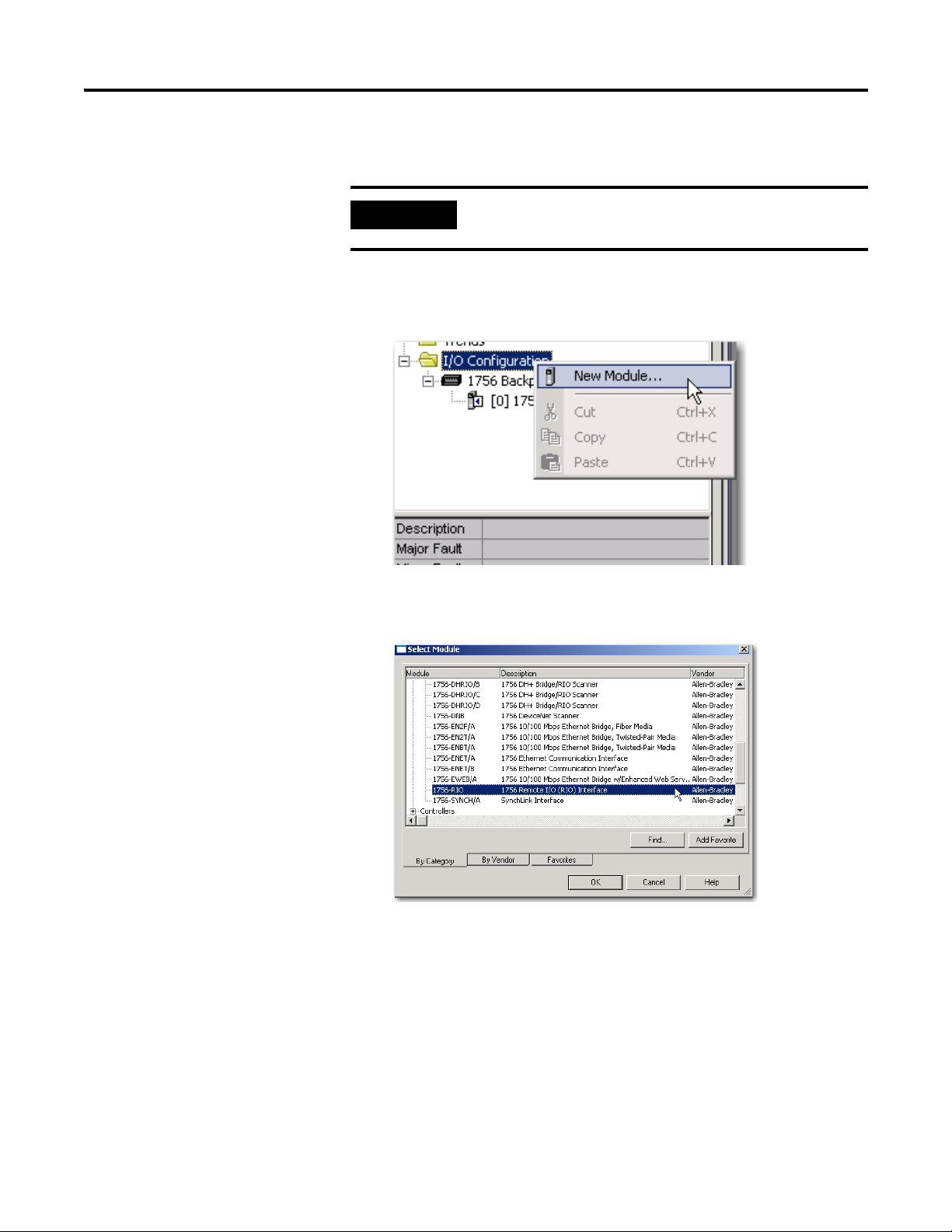
1. On the Controller Organizer, right-click on the I/O Configuration
folder and select New Module from the pull-down menu.
2. On the Select Module dialog box, expand the Communications tab and
select the 1756-RIO module.
3. Click OK.
The 1756-RIO Module Properties dialog box displays.
24 Publication 1756-UM534B-EN-P - November 2010
Item Description
The 1756-RIO Module-Getting Started Chapter 1
On the Module Properties dialog box, from the General tab, you can
assign the module name, description, slot number, and module
definition.
Name Choose a name that easily identifies the module.
Description The Description field is optional.
Slot The Slot field must match the slot number of the 1756-RIO module’s location in the chassis.
Module Definition-
Change … button
Click on the Change … button to change the Series, Revision, Electronic Keying, Mode (scanner or adapter),
or Number of Input or Output Tags. The Module Definition dialog box displays.
The Module Definition dialog box displays.
4. Click OK on the Module Definition dialog box.
5. Click Yes to accept any changes.
6. Click OK again on the bottom of the General tab.
Publication 1756-UM534B-EN-P - November 2010 25

Chapter 1 The 1756-RIO Module-Getting Started
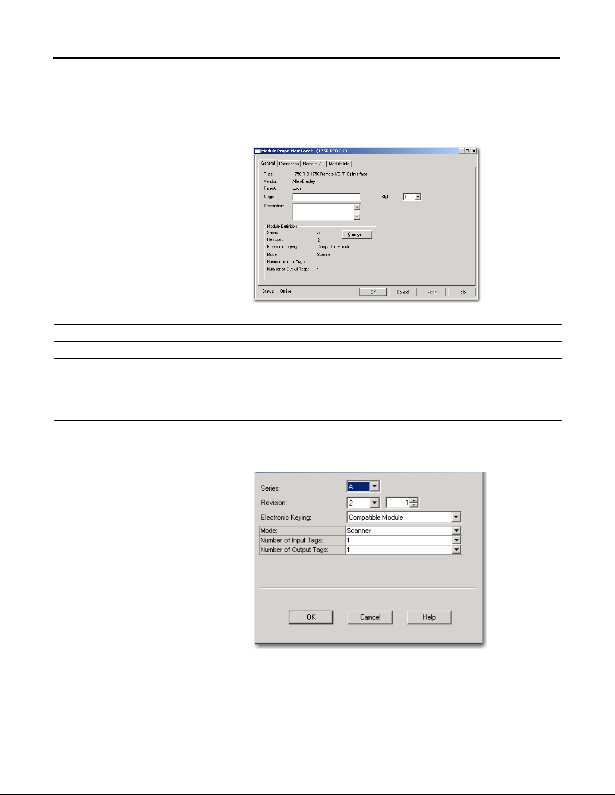
Module Definition Dialog Box
Item Description
Series Module series letter.
Revision Firmware revision number.
Electronic Keying Exact Match: requires all keying attributes of the physical module and the module created in the software to
match precisely to establish communication.
Compatible Module: the module determines whether to accept or reject communication. Compatible Keying
allows the physical module to accept the key of the module configured in the software, provided that the
configured module is one the physical module is capable of emulating. This is the default setting.
Disabled Keying: indicates the keying attributes are not considered when attempting to communicate with a
module. Be extremely cautious when using this option; if used incorrectly, this option can lead to personal injury
or death, property damage, or economic loss.
Mode - Scanner or
Adapter
The module ships in scanner mode. (The 4-character display on the front of the module also indicates which mode
is set.) If you want to change the mode setting, you must first select the desired mode in the add-on profile on the
Module Definition dialog box from the pull-down menu, so that the correct configuration tool starts. Then, on the
Remote I/O tab, you must click on the Configure Remote I/O devices button (the configuration tool), and select the
Tools menu>Set 1756-RIO Module/Scanner mode to download the correct firmware.
Be aware that changing the module mode downloads firmware specific to the mode chosen. This mode setting
must match between the RSLogix 5000 programming software project and the configuration tool, but keep in
mind that the correct firmware must also be downloaded.
Input Tags - Output
Tags
Up to 10 input and output tags can be selected. Each tag is 248 words. The number of input/output tags entered
in the add-on profile’s Module Properties has to be equal or greater than the number of tags in the configuration
tool.
The number of tags in the configuration tool are determined by the mappings you create. The more tags you have,
the more backplane traffic is generated. It’s best to keep the number of tags low, which is what the automatic
mapping command does, by mapping the data and packing it into the lowest number of tags.
For example, a single rack with discrete data that has the inputs/outputs mapped to block 9 requires the input/
output tags to be 10. So, in the Module Properties>General tab>Module Definition>Change button, select 10 for
the number of input and output tags.
26 Publication 1756-UM534B-EN-P - November 2010
The 1756-RIO Module-Getting Started Chapter 1
IMPORTANT
Enter the RPI
To set the RPI, follow these steps.
1. On the controller organizer, double-click on the RIO module.
2. On the Module Properties dialog box, from the Connection tab, set the
RPI for the module.
If you are using the 1756-RIO module in a remote rack, for
example, a rack connected to the controlling ControlLogix
controller over ControlNet or Ethernet/IP, it may be necessary to
increase the RPI, as the intermediate network may not have
sufficient bandwidth to support faster updates (small RPIs). The
likelihood of having bandwidth issues is increased as you
increase the number of 248-word input and output tags.
Publication 1756-UM534B-EN-P - November 2010 27
Chapter 1 The 1756-RIO Module-Getting Started
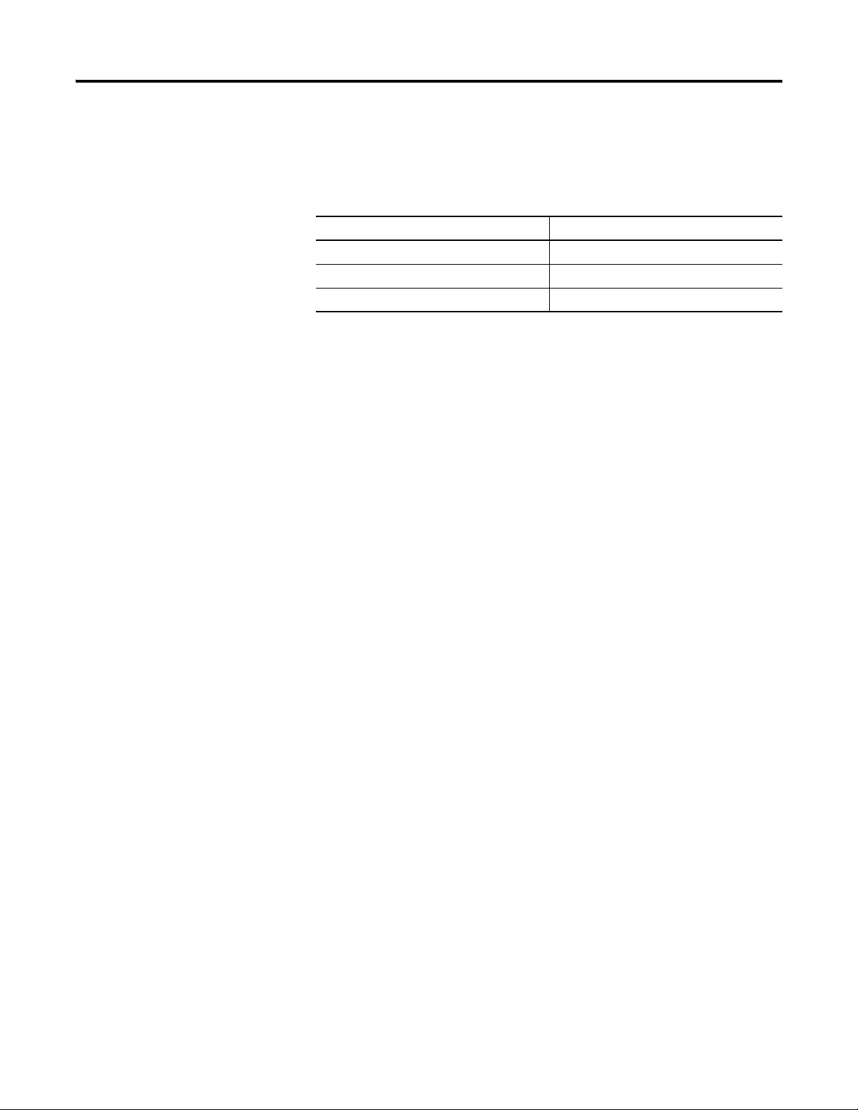
Remote I/O Update Time
The remote update time is the time it takes the Remote I/O scanner to scan all
of the adapters in its I/O scan list.
Baud Rate Scan Rate
230.4 K 3 ms
115.2 K 5 ms
57.6 K 8 ms
The scan rate is the approximate time it takes to scan a 16-slot logical chassis
without block transfers. The number and sizes of block transfers can
significantly affect this time.
So, for example, if you have eight adapters on your network and your baud rate
is 230.4 K, your approximate remote I/O update time would be 8 (# of
adapters) * 3 ms (scan rate), or, 24 ms.
RPI
The Requested Packet Interval (RPI) specifies the rate at which the 1756-RIO
module and the ControlLogix controller exchange data to and from each
other. The allowable RPI’s range is from 2…750 ms, with a default of 20 ms.
When the specified time frame elapses, the 1756-RIO module and the
ControlLogix controller produce data for each other. All 1756-RIO input and
output tags update with the same RPI.
Select an RPI for your application. For most applications, a good rule of
thumb would be to set the RPI equal to one half of the remote I/O scan time.
28 Publication 1756-UM534B-EN-P - November 2010

The 1756-RIO Module-Getting Started Chapter 1
Throughput
When using the 1756-RIO module, your system throughput is based on the
following key factors:
Number and sizes of adapters
Number and sizes of block transfer modules
Overall remote I/O update time
RPI
Any network cards involved
Controller scan time
The asynchronous nature of the RPI and the remote I/O scan
Since the RIO scan is asynchronous to the RPI, the worst case, or maximum
update time to get information from the 1756-RIO into the controller is the
RPI plus two times the remote I/O update rate.
You can use the diagnostic functions of the 1756-RIO configuration tool’s
utilities to measure the average, minimum, and maximum update times on the
Remote I/O network.
Publication 1756-UM534B-EN-P - November 2010 29
Chapter 1 The 1756-RIO Module-Getting Started
ATTENTION
IMPORTANT
Set Communication Path and Download to the Controller in the RSLogix 5000 Project
Follow these steps to set the communication path and download to the
controller.
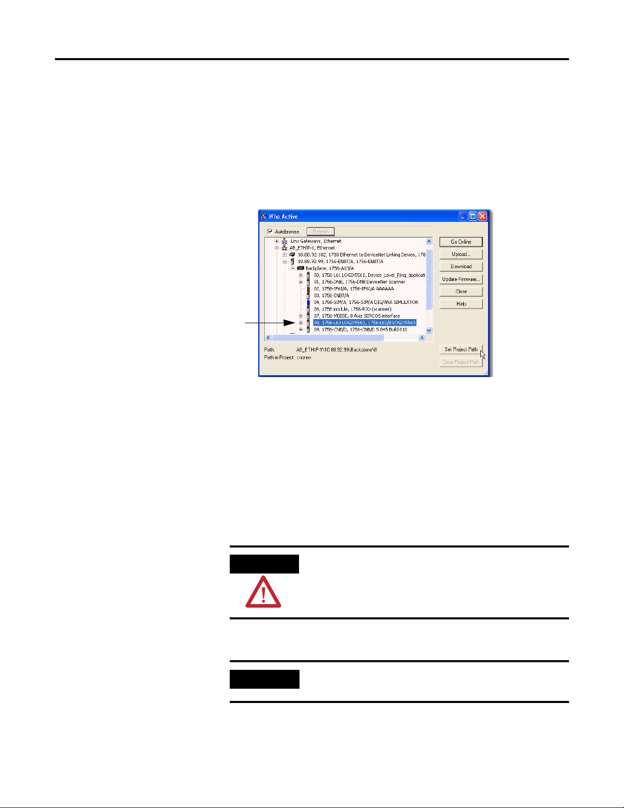
1. On the main menu, from the Communications menu, select Who
Active.
2. Browse to the controller.
Launch the Configuration Tool and Select the Module Mode
3. Click the Set Project Path button.
4. Click Download.
Once the desired module mode is set in the RSLogix 5000 module properties,
you must select the mode in the configuration tool to download the correct
firmware. You must first launch the configuration tool and then verify the
mode setting matches in the Module Properties and in the configuration tool.
The correct firmware must be downloaded for the module to run correctly.
If your desired mode is scanner mode, you do nothing at this
point, as the module ships in scanner mode.
The controller must be in Program Mode to continue with the
firmware update.
30 Publication 1756-UM534B-EN-P - November 2010
Loading...