


Reference Manual
Bulletin 1606 Switched Mode Power Supplies
Catalog Number: 1606-XLS960E-3
Index
|
|
Page |
|
|
Page |
1. |
Intended Use ....................................................... |
3 |
22. Certifications .................................................. |
18 |
|
2. |
Installation Requirements................................... |
3 |
23. Physical Dimensions and Weight .................... |
19 |
|
3. |
AC-Input............................................................... |
4 |
24. Accessories ....................................................... |
20 |
|
4. |
Input Inrush Current ........................................... |
5 |
24.1. |
Wall mounting bracket - 1606-XLC......... |
20 |
5. |
DC-Input............................................................... |
5 |
24.2. |
Buffer module - 1606-XLSBUFFER24........ |
20 |
6. |
Output ................................................................. |
6 |
24.3. |
1606-XLSRED80 - Redundancy Modules... |
20 |
7. |
Hold-up Time....................................................... |
8 |
25. Application Notes............................................. |
21 |
|
8. |
DC-OK Relay Contact .......................................... |
9 |
25.1. |
Repetitive Pulse Loading.......................... |
21 |
9. |
Shut-down Input ................................................. |
9 |
25.2. |
Peak Current Capability ........................... |
22 |
10. |
Remote Control of Output Voltage ................. |
10 |
25.3. |
External Input Protection......................... |
22 |
11. |
Internal Data Logging....................................... |
10 |
25.4. |
Using only 2 Legs of a 3-Phase System .... |
23 |
12. |
Efficiency and Power Losses.............................. |
11 |
25.5. |
Charging Batteries ............................... |
24 |
13. |
Reliability........................................................... |
12 |
25.6. |
Output Circuit Breakers............................ |
24 |
14. |
Functional Diagram........................................... |
12 |
25.7. |
Parallel Use to Increase Output Power.... |
25 |
15. |
Terminals and Wiring........................................ |
13 |
25.8. |
Parallel Use for Redundancy .................... |
25 |
16. Front Side and User Elements........................... |
14 |
25.9. |
Series Operation ....................................... |
26 |
|
17. |
EMC.................................................................... |
15 |
25.10. Inductive and Capacitive Loads................ |
26 |
|
18. |
Environment ...................................................... |
16 |
25.11. Back-feeding Loads .................................. |
26 |
|
19. Protection Features ........................................... |
17 |
25.12. Use in a Tightly Sealed Enclosure ............ |
26 |
||
20. |
Safety Features.................................................. |
17 |
25.13. Mounting Orientations ............................ |
27 |
|
21. |
Dielectric Strength ............................................ |
18 |
|
|
|
Terminology and Abbreviations
•PE and  symbol—PE is the abbreviation for Protective Earth and has the same meaning as the symbol
  .
.
•Earth, Ground—This document uses the term “earth” which is the same as the U.S. term “ground”.
•T.b.d.—To be defined, value or description will follow later.
•AC 400V—A figure displayed with the AC or DC before the value represents a nominal voltage with standard tolerances (usually ±15%) included. E.g.: DC 12V describes a 12V battery whether it is full (13.7V) or flat (10V)
•400Vac—A figure with the unit (Vac) at the end is a momentary figure without any additional tolerances included.
•50Hz vs. 60Hz—As long as not otherwise stated, AC 230V parameters are valid at 50Hz mains frequency.
•may—A key word indicating flexibility of choice with no implied preference.
•shall—A key word indicating a mandatory requirement.
•should—A key word indicating flexibility of choice with a strongly preferred implementation.
Bulletin 1606 Switched Mode Power Supplies
Description
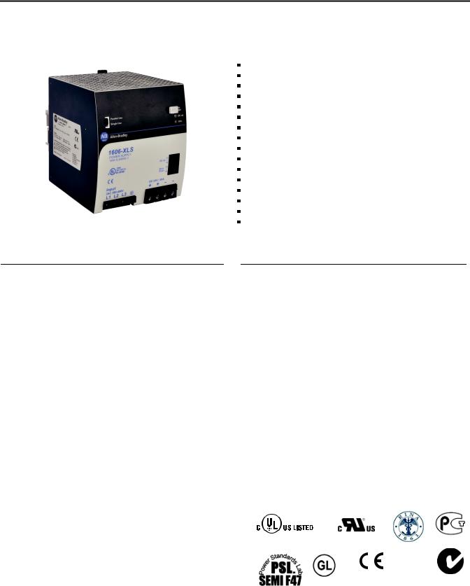
The most outstanding features of the 1606-XLS960E-3 DIN rail power supply are its extremely high efficiencies and its small size, which are achieved by a synchronous rectification and other technological breakthroughs.
Large power reserves of 150% support the starting of heavy loads such as DC motors or capacitive loads. In many cases this allows the use of a unit from a lower wattage class which saves space and money.
High immunity to transients and power surges as well as low electromagnetic emission allow the use of these power supplies in nearly every environment.
The integrated output power manager, the three input fuses and near zero input inrush current make installation and usage simple. Diagnostics are easy due to the DC-ok relay, a green DC-OK LED and the red overload LED.
A large international approval package for a variety of applications makes this unit suitable for nearly every application.
Power Supply
3AC 380-480V Wide-range Input Three Input Fuses Included
Width only 110mm, Weight only 1.5kg
95.3% Full Load and Excellent Partial Load Efficiencies
50% BonusPower, 1440W for up to 4s
110A Peak Current for 25ms for Easy Fuse Tripping Active PFC (Power Factor Correction)
Active Filtering of Input Transients Negligible Low Input Inrush Current Surge Full Power Between -25°C and +60°C Current Sharing Feature for Parallel Use
Internal Data Logging for Troubleshooting Included. Remote Control of Output Voltage
DC-OK Relay Contact Shut-down Input
3 Year Warranty
 Specification Quick Reference
Output voltage |
DC 24V |
nominal |
|
Adjustment range |
24 - 28V |
|
|
Output current |
40 – 34.3A |
continuous |
|
|
60 – 51.5A |
short term (4s) |
|
Output power |
960W |
continuous |
|
|
1440W |
short term (4s) |
|
Output ripple |
< 100mVpp |
20Hz to 20MHz |
|
Input voltage |
3AC 380-480V |
-15%/+20% |
|
Mains frequency |
50-60Hz |
±6% |
|
AC Input current |
1.65 |
/ 1.35A |
at 3x400 / 480Vac |
Power factor |
0.88 |
/ 0.90 |
at 3x400 / 480Vac |
AC Inrush current |
typ. 4.5A peak |
|
|
Efficiency |
95.3 |
/ 95.2% |
at 3x400 / 480Vac |
Losses |
47.3 |
/ 48.4W |
at 3x400 / 480Vac |
Temperature range |
-25°C to +70°C |
operational |
|
Derating |
24W/°C |
+60 to +70°C |
|
Hold-up time |
typ. 25 / 25ms |
at 3x400 / 480Vac |
|
Dimensions |
110x124x127mm WxHxD |
||
Weight |
1500g / 3.3 lb |
|
|
|
Catalog Numbers |
|
|
|
|
|
Certifications |
|
|
|
|
|
|
|
|
|
|
|
|||
|
Power Supply |
1606-XLS960E-3 24-28V Standard unit |
|
|
|
|
|
|
||
|
|
|
|
|
|
|
||||
|
|
|
|
|
|
|
||||
|
Accessories |
1606-XLC |
Wall mount bracket |
|
|
|
IND. CONT. EQ. |
UL 60950-1 |
GOST R |
|
|
|
1606-XLSBUFFER24 |
Buffer unit |
|
|
|
UL 508 |
|||
|
|
|
|
|
Marine RINA |
|
||||
|
|
1606-XLSRED80 |
Redundancy module |
|
|
|
|
|
|
|
|
|
|
|
|
|
|
|
Marine |
EMC, LVD, RoHS |
C-Tick |
|
All parameters are specified at 24V, 40A, 3x400Vac, 25°C ambient and after a 5 minutes run-in time, unless noted otherwise. |
2 |
Rockwell Automation Publication 1606-RM005A-EN-P - February 2014 |
|
Bulletin 1606 Switched Mode Power Supplies |
|
|
1. |
Intended Use |
• |
This device is designed for installation in an enclosure and is intended for the general professional use such as in industrial control, office, |
|
communication, and instrumentation equipment. |
• |
Do not use this power supply in equipment where malfunction may cause severe personal injury or threaten human life. |
• |
This device is designed for use in non-hazardous, ordinary or unclassified locations. |
2. |
Installation Requirements |
•This device may only be installed and put into operation by qualified personnel.
•This device does not contain serviceable parts. The tripping of an internal fuse is caused by an internal defect.
•If damage or malfunction should occur during installation or operation, immediately turn power off and send unit to the factory for inspection.
•Mount the unit on a DIN rail so that the output and input terminals are located on the bottom of the unit. For other mounting orientations, see derating requirements in this document. Refer to section 25.13.
•This device is designed for convection cooling and does not require an external fan. Do not obstruct airflow and do not cover ventilation grid (e.g. cable conduits) by more than 30%!
•Keep the following installation clearances: 40mm on top, 20mm on the bottom, 5mm on the left and right sides are recommended when the device is loaded permanently with more than 50% of the rated power. Increase this clearance to 15mm in case the adjacent device is a heat source (e.g. another power supply).
SHOCK HAZARD: Do not use the power supply without proper grounding (Protective Earth). Use the terminal on the input block for earth connection and not one of the screws on the housing.
-Turn power off before working on the device. Protect against inadvertent re-powering
-Make sure that the wiring is correct by following all local and national codes
-Do not modify or repair the unit
-Do not open the unit as high voltages are present inside
-Use caution to prevent any foreign objects from entering the housing
-Do not use in wet locations or in areas where moisture or condensation can be expected
-Do not touch during power-on, and immediately after power-off. Hot surfaces may cause burns.
WARNING: EXPLOSION HAZARDS!
Substitution of components may impair suitability for this environment. Do not disconnect the unit or operate the voltage adjustment or S/P jumper unless power has been switched off or the area is known to be non-hazardous.
All parameters are specified at 24V, 40A, 3x400Vac, 25°C ambient and after a 5 minutes run-in time, unless noted otherwise. |
|
Rockwell Automation Publication 1606-RM005A-EN-P - February 2014 |
3 |

Bulletin 1606 Switched Mode Power Supplies

 3. AC-Input
AC input |
nom. |
3AC 380-480V |
suitable for TN, TT and IT mains networks, |
|
|
|
|
grounding of one phase is allowed except in UL 508 |
|
|
|
|
applications |
|
AC input range |
min. |
3x 323-576Vac |
continuous operation |
|
Allowed voltage L to earth |
max. |
576Vac |
continuous, IEC 60664-1 |
|
Input frequency |
nom. |
50–60Hz |
±6% |
|
|
|
|
|
|
Turn-on voltage |
typ. |
3x 305Vac |
steady-state value, load independent, see Fig. 3-1 |
|
Shut-down voltage |
typ. |
3x 275Vac |
steady-state value, load independent, see Fig. 3-1 |
|
|
|
3AC 400V |
3AC 480V |
|
Input current |
typ. |
1.65A |
1.35A |
at 24V, 40A, symmetrical phase voltages, |
|
|
|
|
see Fig. 3-3 |
Power factor*) |
typ. |
0.88 |
0.90 |
at 24V, 40A, see Fig. 3-4 |
Start-up delay |
typ. |
500ms |
600ms |
see Fig. 3-2 |
Rise time |
typ. |
35ms |
35ms |
at 24V, 40A, resistive load, 0mF see Fig. 3-2 |
|
typ. |
40ms |
40ms |
at 24V, 40A, resistive load, 40mF see Fig. 3-2 |
|
|
|
|
|
Turn-on overshoot |
max. |
500mV |
500mV |
see Fig. 3-2 |
|
||||
*) The power factor is the ratio of the true (or real) power to the apparent power in an AC circuit. |
||||
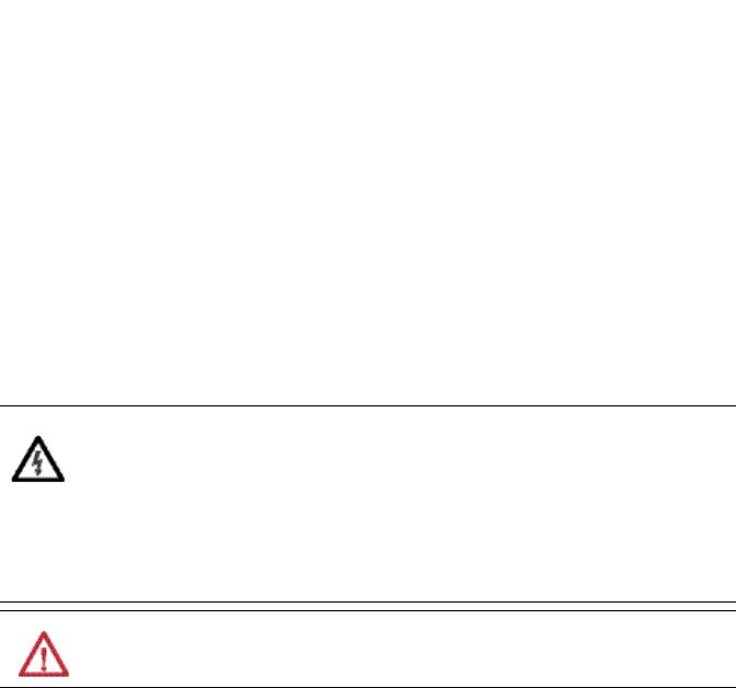
Fig. 3-1 Input voltage range |
|
Fig. 3-2 Turn-on behavior, definitions |
||
POUT |
|
Rated input range |
|
Shut-down |
Turn-on |
|
|
|
|
|
VIN |
275V 305V |
323V |
576Vac |
|
Input |
|
|
|
|
Voltage |
|
|
|
|
L1 |
L2 |
L3 |
|
|
Output |
|
- 5% |
|
Overshoot |
|
|
|
||
Voltage |
|
|
|
|
|
Start-up |
Rise |
||
|
|
delay |
Time |
|
Fig. 3-3 Input current vs. output load at 24V |
Fig. 3-4 Power factor vs. output load at 24V |
||||||||||||||||
Input Current, typ. |
|
|
|
|
|
Power Factor, typ. |
|
|
|
|
|||||||
1.6A |
|
|
|
|
|
|
|
|
0.95 |
|
|
|
|
|
|
|
|
|
|
|
|
|
|
|
|
|
A: 3x 400Vac |
|
|
|
|
|
|||
1.4 |
A: 3x 400Vac |
|
|
|
|
|
|
|
|
|
|
|
|||||
|
|
|
|
|
0.90 |
B: 3x 480Vac |
|
|
B |
|
|
||||||
1.2 |
|
|
|
|
|
|
|
A |
|
||||||||
B: 3x 480Vac |
|
|
|
A |
|
|
|
|
|
|
|
|
|
||||
|
|
|
|
|
|
|
|
|
|
|
|
|
|
|
|
|
|
1.0 |
|
|
|
|
|
|
B |
|
0.85 |
|
|
|
|
|
|
|
|
0.8 |
|
|
|
|
|
|
|
|
0.80 |
|
|
|
|
|
|
|
|
0.6 |
|
|
|
|
|
|
|
|
|
|
|
|
|
|
|
|
|
|
|
|
|
|
|
|
|
|
|
|
|
|
|
|
|
|
|
0.4 |
|
|
|
|
|
|
|
|
0.75 |
|
|
|
|
|
|
|
|
0.2 |
|
|
|
|
|
|
|
|
|
|
|
|
|
|
|
|
|
|
|
|
|
|
Output Current |
|
|
|
|
|
|
Output Current |
|||||
0 |
|
|
|
|
|
0.70 |
|
|
|
|
|
||||||
|
|
|
|
|
|
|
|
|
|
|
|
|
|
|
|
||
4 |
8 |
12 |
16 |
20 |
24 |
28 |
32 |
36 40A |
4 |
8 |
12 |
16 |
20 |
24 |
28 |
32 |
36 40A |
|
All parameters are specified at 24V, 40A, 3x400Vac, 25°C ambient and after a 5 minutes run-in time, unless noted otherwise. |
4 |
Rockwell Automation Publication 1606-RM005A-EN-P - February 2014 |

Bulletin 1606 Switched Mode Power Supplies
4. Input Inrush Current
The power supply is equipped with an active inrush current limitation circuit, which limits the input inrush current after turn-on to a negligible low value. The input current is usually smaller than the steady state input current.
|
|
3AC 400V |
3AC 480V |
|
Inrush current*) |
max. |
6Apeak |
6Apeak |
over entire temperature range |
|
typ. |
4.5Apeak |
4.5Apeak |
over entire temperature range |
Inrush energy |
max. |
1.5A2s |
1.5A2s |
over entire temperature range |
Inrush delay |
typ. |
500ms |
600ms |
|
*) The charging current into EMI suppression capacitors is disregarded in the first microseconds after switch-on.
Fig. 4-1 Typical turn-on behaviour at nominal load and 25°C ambient temperature
Input Current 2A/DIV
Input
3x400Vac
24Vdc
Output 100ms/DIV
5. DC-Input
Do not operate this power supply with DC input voltage.
All parameters are specified at 24V, 40A, 3x400Vac, 25°C ambient and after a 5 minutes run-in time, unless noted otherwise. |
|
Rockwell Automation Publication 1606-RM005A-EN-P - February 2014 |
5 |

Bulletin 1606 Switched Mode Power Supplies

 6. Output
Output voltage |
nom. |
24V |
|
|
|
Adjustment range |
min. |
24-28V |
guaranteed |
|
|
|
|
max. |
30V***) |
at clockwise end position of potentiometer |
|
Factory setting |
typ. |
24.1V |
±0.2%, at full load, cold unit, in “single use” mode |
||
|
|
typ. |
24.1V |
±0.2%, at full load, cold unit, in “parallel use” mode |
|
|
|
typ. |
25.1V |
at no load, cold unit, in “parallel use” mode |
|
Line regulation |
max. |
10mV |
3x323-576Vac |
|
|
Load regulation |
max. |
50mV |
in “single use” mode: static value, 0A |
40A, see Fig. 6-1 |
|
|
|
typ. |
1000mV |
in “parallel use” mode: static value, 0A |
40A, |
|
|
|
|
see Fig. 6-2 |
|
Ripple and noise voltage |
max. |
100mVpp |
20Hz to 20MHz, 50Ohm |
|
|
Output current |
nom. |
40A |
continuously available at 24V, see Fig. 6-1 and Fig. 6-2 |
||
|
|
nom. |
34.3A |
continuously available at 28V, see Fig. 6-1 and Fig. 6-2 |
|
|
|
nom. |
60A |
short term (4s) available BonusPower*) |
, at 24V, |
|
|
|
|
see Fig. 6-1, Fig. 6-2 and Fig. 6-4 |
|
|
|
nom. |
51.5A |
short term (4s) available BonusPower*) |
, at 28V, |
|
|
|
|
see Fig. 6-1, Fig. 6-2 and Fig. 6-4 |
|
|
|
typ. |
110A |
up to 25ms, output voltage stays above 20V, see Fig. |
|
|
|
|
|
6-4. This peak current is available once every second. |
|
|
|
|
|
See section 25.2 for more peak current measurements. |
|
Output power |
nom. |
960W |
continuously available at 24-28V |
|
|
|
|
nom. |
1440W*) |
short term available BonusPower*) at 24-28V |
|
BonusPower time |
typ. |
4s |
duration until the output voltage dips, see Fig. 6-3 |
||
BonusPower recovery time |
typ. |
7s |
overload free time to reset power manager, see Fig. 6-5 |
||
Overload behavior |
|
cont. current |
see Fig. 6-1 |
|
|
|
|
|
|
||
Short-circuit current**) |
min. |
40A |
continuous, load impedance 25mOhm, see Fig. 6-1 |
||
|
|
max. |
44A |
continuous, load impedance 25mOhm, see Fig. 6-1 |
|
|
|
min. |
60A |
short-term (4s), load impedance 25mOhm, see Fig. 6-1 |
|
|
|
max. |
68A |
short-term (4s), load impedance 25mOhm, see Fig. 6-1 |
|
|
|
typ. |
46A |
continuous, load impedance <10mOhm |
|
|
|
max. |
51A |
continuous, load impedance <10mOhm |
|
Output capacitance |
typ. |
10 200μF |
included in the power supply |
|
|
*) |
BonusPower, short term power capability (up to typ. 4s) |
|
|
||
|
The power supply is designed to support loads with a higher short-term power requirement without damage or shutdown. The short- |
||||
|
term duration is hardware-controlled by an output power manager. BonusPower is repeatedly available. Detailed information |
||||
|
can be found in section 25.1. If the power supply is loaded longer with the BonusPower than shown in the bonus-time diagram (see |
||||
|
Fig. 6-3), the max. output power is automatically reduced to 960W. |
|
|
||
**) |
Discharge current of output capacitors is not included. |
|
|
||
***) |
This is the maximum output voltage which can occur at the clockwise end position of the potentiometer due to tolerances. There is no |
||||
|
guarantee that this value can be achieved. The typical value is about 28.5V. |
|
|||
|
All parameters are specified at 24V, 40A, 3x400Vac, 25°C ambient and after a 5 minutes run-in time, unless noted otherwise. |
6 |
Rockwell Automation Publication 1606-RM005A-EN-P - February 2014 |

Bulletin 1606 Switched Mode Power Supplies
Fig. 6-1 Output voltage vs. output current in
“single use” mode, typ.
Output Voltage |
|
Adjustment Range |
|
|||||
|
|
|
|
|
|
|||
28V |
|
|
A |
|
|
B |
|
|
24 |
|
|
|
|
|
|
||
|
|
|
|
|
|
|
|
|
20 |
|
|
|
|
|
|
|
|
16 |
|
|
|
|
A |
|
B |
|
12 |
A Continuously |
|
|
|
||||
|
|
|
|
|
||||
|
available |
|
|
|
|
|
||
8 |
B |
Short-term (4s) |
|
|
|
|
||
|
|
BonusPower |
|
|
|
|
|
|
4 |
|
|
|
|
|
|
|
|
0 |
|
|
|
|
|
|
|
|
0 |
|
10 |
20 |
30 |
40 |
50 |
60 |
70A |
|
|
|
|
|
|
Output Current |
||
Fig. 6-3 Bonus time vs. output power
Bonus Time |
|
|
|
|
|
|
|
|
|
|
|
|
|
|
|
|
|
|
|
|
|
|
|
|
|
|
|
|
|
|
|
|
|
|
|
|
|
|
|
|
|||||||||
5s |
|
|
|
|
|
|
|
|
|
|
|
|
|
|
|
|
|
|
|
|
|
|
|
|
|
|
|
|
|
|
|
|
|
|
|
|
|
|
|
|
|
|
|
|
|
|
|
|
|
4 |
|
|
|
|
|
|
|
|
|
|
|
|
|
|
|
|
|
|
|
|
|
|
|
|
|
|
|
|
|
|
max. |
|
|
|
|
|
|
|
|
|
|
|
|
|
|||||
|
|
|
|
|
|
|
|
|
|
|
|
|
|
|
|
|
|
|
|
|
|
|
|
|
|
|
|
|
|
|
|
|
|
|
|
|
|
|
|
|
|
|
|
|
|
|
|
|
|
|
|
|
|
|
|
|
|
|
|
|
|
|
|
|
|
|
|
|
|
|
|
|
|
|
|
|
|
|
|
|
|
|
|
|
|
|
|
|
|
|
|
|
|
|
|
|
|
|
|
|
|
|
|
|
|
|
|
|
|
|
|
|
|
|
|
|
|
|
|
|
|
|
|
|
|
|
|
|
|
|
|
|
|
|
|
|
|
|
|
|
|
|
|
||||||
3 |
|
|
|
|
|
|
|
|
|
|
|
|
|
|
|
|
|
|
|
|
|
|
|
|
|
|
|
|
|
min. |
|
|
|
|
|
|
|
|
|
|
|
|
|
||||||
|
|
|
|
|
|
|
|
|
|
|
|
|
|
|
|
|
|
|
|
|
|
|
|
|
|
|
|
|
|
|
|
|
|
|
|
|
|
|
|
|
|
||||||||
|
|
|
|
|
|
|
|
|
|
|
|
|
|
|
|
|
|
|
|
|
|
|
|
|
|
|
|
|
|
|
|
|
|
|
|
|
|
|
|
|
|
|
|
|
|
|
|
|
|
2 |
|
|
|
|
|
|
|
|
|
|
|
|
|
|
|
|
|
|
|
|
|
|
|
|
|
|
|
|
|
|
|
|
|
|
|
|
|
|
|
|
|
|
|
|
|
|
|
|
|
|
|
|
|
|
|
|
|
|
|
|
|
|
|
|
|
|
|
|
|
|
|
|
|
|
|
|
|
|
|
|
|
|
|
|
|
|
|
|
|
|
|
|
|
|
|
|
|
|
|
|
|
|
|
|
|
|
|
|
|
|
|
|
|
|
|
|
|
|
|
|
|
|
|
|
|
|
|
|
|
|
|
|
|
|
|
|
|
|
|
|
|
|
|
|
|
|
|
|
|
|
|
|
|
|
|
|
|
|
|
|
|
|
|
|
|
|
|
|
|
|
|
|
|
|
|
|
|
|
|
|
|
|
|
|
|
|
|
|
|
|
|
|
|
|
|
|
|
|
|
|
|
|
|
|
|
|
|
|
|
|
|
|
|
|
|
|
|
|
|
|
|
|
|
|
|
|
|
|
|
|
|
|
|
|
|
|
|
|
|
|
|
|
|
|
|
|
|
|
|
1 |
|
|
|
|
|
|
|
|
|
|
|
|
|
|
|
|
|
|
|
|
|
|
|
|
|
|
|
|
|
|
|
|
|
|
|
|
|
|
|
|
|
|
|
|
|
|
|
|
|
|
|
|
|
|
|
|
|
|
|
|
|
|
|
|
|
|
|
|
|
|
|
|
|
|
|
|
|
|
|
|
|
|
|
|
|
|
|
|
|
|
|
|
|
|
|
|
|
|
|
|
|
|
|
|
|
|
|
|
|
|
|
|
|
|
|
|
|
|
|
|
|
|
|
|
|
|
|
|
|
|
|
|
|
|
|
|
|
|
|
|
|
|
|
|
|
|
|
|
|
|
|
|
|
|
|
|
|
|
|
|
|
|
|
|
|
|
|
|
|
|
|
|
|
|
|
|
|
|
|
|
|
|
|
|
|
|
|
|
|
|
|
|
|
|
|
|
|
|
|
|
|
|
|
|
|
|
|
|
|
|
|
|
|
|
|
|
|
|
|
|
|
|
|
|
|
|
|
|
|
|
|
|
|
|
|
|
|
|
|
|
|
|
|
|
|
|
|
|
|
0 |
|
|
|
|
|
|
|
|
|
|
|
|
|
|
|
|
|
Output Power |
|
|
|
|
|
|
|
|
|
|
|
|
|
|
|||||||||||||||||
|
|
|
|
|
|
|
|
|
|
|
|
|
|
|
|
|
|
|
|
|
|
|
|
|
|
|
|
|
|
|
|
|
|
|
|
|
|
|
|
|
|
|
|
|
|
|
|
|
|
100 |
110 |
120 |
130 |
140 |
150 |
160 |
170% |
||||||||||||||||||||||||||||||||||||||||||
|
|
|
|
|
|
|
|
|
|
|
|
|
|
|
|
|
|
|
|
|
|
|
|
|
|
|
|
|
|
|
|
|
|
|
|
|
|
|
|
|
|
|
|
|
|
|
|
|
|
Fig. 6-5 BonusPower recovery time
|
Limitation by |
Power |
Power Manager |
Demand |
|
100% |
|
|
t |
Bonus |
Recovery Time |
|
Time |
|
Bonus Power disabled |
|
|
Output |
|
|
|||
Voltage |
|
|
|
||
t
Fig. 6-2 Output voltage vs. output current in
“parallel use” mode, typ.
Output Voltage (Parallel Use, typ.) |
|
|
|||||
29V |
|
|
|
Adjustment Range |
|
||
28V |
|
|
|
|
|
|
|
27V |
|
|
|
|
A |
|
B |
26V |
|
|
Factory |
|
|
|
|
25V |
|
|
setting |
|
|
|
|
|
|
|
|
|
|
|
|
24V |
A Continuously |
|
|
|
|
||
23V |
|
available |
|
|
|
|
|
B |
Short-term (4s) |
|
A |
|
B |
||
22V |
BonusPower |
|
|
|
|
||
|
|
|
|
|
|
|
|
0 |
|
10 |
20 |
30 |
40 |
50 |
60A |
Output Current
Fig. 6-4 Dynamic overcurrent capability, typ.
Output Voltage (dynamic behavior, < 25ms)
28V |
|
|
|
|
|
|
24 |
|
|
|
|
|
|
20 |
Adjustment |
|
|
|
||
16 |
|
Range |
|
|
|
|
|
|
|
|
|
|
|
12 |
|
|
|
|
|
|
8 |
|
|
|
|
|
|
4 |
|
|
Output Current |
|||
0 |
|
|
||||
|
|
|
|
|
|
|
0 |
15 |
30 |
45 |
60 |
75 |
90 105120135 150A |
BonusPower is available as soon as power comes on and after the end of an output short circuit or overload.
Fig. 6-6 BonusPower after input turn-on
Input
Voltage
Output
Voltage
150% Bonus
Power
Output 100%
Power
Fig. 6-7 BonusPower after output short
|
Short of |
|
|
Output |
|
Output |
|
|
Voltage |
|
|
Output |
150% |
Bonus |
100% |
Power |
|
Power |
|
All parameters are specified at 24V, 40A, 3x400Vac, 25°C ambient and after a 5 minutes run-in time, unless noted otherwise. |
|
Rockwell Automation Publication 1606-RM005A-EN-P - February 2014 |
7 |
Bulletin 1606 Switched Mode Power Supplies
7. Hold-up Time
|
|
3AC 400V*) |
3AC 480V*) |
|
Hold-up Time |
typ. |
50ms |
50ms |
at 24V, 20A, see Fig. 7-1 |
|
min. |
40ms |
40ms |
at 24V, 20A, see Fig. 7-1 |
|
typ. |
25ms |
25ms |
at 24V, 40A, see Fig. 7-1 |
|
min. |
20ms |
20ms |
at 24V, 40A, see Fig. 7-1 |
*) Curves and figures for operation on only 2 legs of a 3-phase system can be found in section 25-4. |
||||
Fig. 7-1 Hold-up time vs. input voltage |
|
Fig. 7-2 Shut-down behavior, definitions |
||
Hold-up Time |
|
24V, 20A, typ. |
||
50ms |
|
|
||
|
|
|
|
|
40 |
|
|
24V, 20A, min. |
|
|
|
|
|
|
30 |
|
|
24V, 40A, typ. |
|
|
|
|
||
20 |
|
|
24V, 40A, min. |
|
|
|
|
||
10 |
|
|
|
|
0 |
|
Input Voltage |
|
|
|
|
|
|
|
320 |
360 |
400 |
440 |
3x480Vac |
L1 L2 L3
Input
Voltage 


Output |
|
|
|
- 5% |
|
|
|
||
|
|
|
||
Voltage |
|
|
|
|
|
|
|
||
|
|
Hold-up Time
|
All parameters are specified at 24V, 40A, 3x400Vac, 25°C ambient and after a 5 minutes run-in time, unless noted otherwise. |
8 |
Rockwell Automation Publication 1606-RM005A-EN-P - February 2014 |
Bulletin 1606 Switched Mode Power Supplies
 8. DC OK Relay Contact
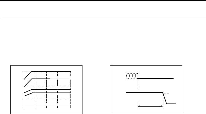
This feature monitors the output voltage, which is produced by the power supply itself. It is independent of a back-fed voltage from a unit connected in parallel to the power supply output.
Contact closes |
As soon as the output voltage reaches 90% of the adjusted output voltage. |
||
Contact opens |
As soon as the output voltage dips more than 10% below the adjusted output voltage. |
||
|
Short dips will be extended to a signal length of 250ms. Dips shorter than 1ms will be ignored. |
||
Contact re-closes |
As soon as the output voltage exceeds 90% of the adjusted voltage. |
||
|
|
|
|
Contact ratings |
max |
60Vdc 0.3A, 30Vdc 1A, 30Vac 0.5A |
resistive load |
|
min |
1mA at 5Vdc |
min. permissible load |
|
|
|
|
Isolation voltage |
See Dielectric Strength table in section 21. |
|
|
|
|
|
|
Fig. 8-1 DC-ok relay contact behavior
|
|
|
|
VOUT = VADJ |
|
10% |
|
0.9* VADJ |
|
|
|
|
|
|
|
< |
> |
250ms |
|
|
1ms |
1ms |
||
open |
closed |
|
open |
closed |
 9. Shut-down Input
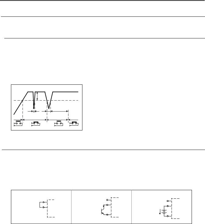
This feature allows a switch-off of the output of the power supply with a signal switch or an external voltage. The shut-down function ramps down and has no safety feature included. The shut-down occurs immediately while the turn-on is delayed up to 350ms. In a shut-down condition, the output voltage is <2V and the output power is <0.5W.
The voltage between different minus pole output terminals must be below 1V when units are connected in parallel. In a series operation of multiple power supplies only wiring option “A” with individual signal switches is allowed.
Please note that option C requires a current sink capability of the voltage source. Do not use a blocking diode.
Fig. 9-1 Activation of the shut-down input
Option A: |
Option B: |
n.c. |
15 |
Shut- |
Option C: |
|
15 Shut- |
15 Shut- |
(via open |
|
n.c. |
||||
|
|
down |
(via external |
||||
collector) |
|
16 |
|
down |
|||
down |
I |
Input |
voltage |
|
|||
16 Input |
|
|
|
+ |
16 Input |
||
|
|
|
|
|
|
||
|
|
|
|
|
|
|
|
OFF: linked |
OFF: I > 0.3mA |
|
- |
|
OFF: U < 1V U |
|
- |
ON : open |
|
|
ON : U = 4 -29V |
|
|||
ON : I < 0.1mA |
|
|
|
|
|||
|
|
|
|
|
|
|
All parameters are specified at 24V, 40A, 3x400Vac, 25°C ambient and after a 5 minutes run-in time, unless noted otherwise. |
|
Rockwell Automation Publication 1606-RM005A-EN-P - February 2014 |
9 |
 Loading...