


 Loading...
Installation Instructions
POINT I/O Module with 8 Configurable 24V DC Points
Catalog Number 1734-8CFG
Topic |
Page |
|
|
|
|
|
|
Important User Information |
2 |
|
|
|
|
|
|
Environment and Enclosure |
3 |
|
|
|
|
|
|
Prevent Electrostatic Discharge |
4 |
|
|
|
|
|
|
About the Module |
5 |
|
|
|
|
|
|
Before You Begin |
5 |
|
|
|
|
|
|
Install the Mounting Base |
7 |
|
|
|
|
|
|
Install the I/O Module |
8 |
|
|
|
|
|
|
Install the Removable Terminal Block |
10 |
|
|
|
|
|
|
Remove a Mounting Base |
11 |
|
|
|
|
|
|
Wire the Module |
13 |
|
|
|
|
|
|
Wiring Diagram |
14 |
|
|
|
|
|
|
Configure the Module |
15 |
|
|
|
|
|
|
Interpret the Indicators |
17 |
|
|
|
|
|
|
Specifications |
19 |
|
|
|
|
|
|
|
|
|
|
|
|
|
|
2 POINT I/O Module with 8 Configurable 24V DC Points
Important User Information
Solid state equipment has operational characteristics differing from those of electromechanical equipment. Safety Guidelines for the Application, Installation and Maintenance of Solid State Controls (Publication SGI-1.1 available from your local Rockwell Automation sales office or online at http://literature.rockwellautomation.com) describes some important differences between solid state equipment and hard-wired electromechanical devices. Because of this difference, and also because of the wide variety of uses for solid state equipment, all persons responsible for applying this equipment must satisfy themselves that each intended application of this equipment is acceptable.
In no event will Rockwell Automation, Inc. be responsible or liable for indirect or consequential damages resulting from the use or application of this equipment.
The examples and diagrams in this manual are included solely for illustrative purposes. Because of the many variables and requirements associated with any particular installation, Rockwell Automation, Inc. cannot assume responsibility or liability for actual use based on the examples and diagrams.
No patent liability is assumed by Rockwell Automation, Inc. with respect to use of information, circuits, equipment, or software described in this manual.
Reproduction of the contents of this manual, in whole or in part, without written permission of Rockwell Automation, Inc., is prohibited.
Throughout this manual, when necessary, we use notes to make you aware of safety considerations.
|
WARNING |
|
Identifies information about practices or circumstances that can cause an explosion |
||
|
|
|
|
|
|
|
|
|
|
|
in a hazardous environment, which may lead to personal injury or death, property |
|
|
|
|
|
damage, or economic loss. |
|
|
|
|
|
|
|
|
|
|
|
|
|
|
|
|
|
Identifies information that is critical for successful application and understanding of |
|
IMPORTANT |
||||
|
the product. |
||||
|
|
|
|
|
|
|
|
|
|
|
|
|
|
|
|
|
|
|
ATTENTION |
|
Identifies information about practices or circumstances that can lead to personal |
||
|
|
|
|
|
|
|
|
|
|
|
injury or death, property damage, or economic loss. Attentions help you identify a |
|
|
|
|
|
hazard, avoid a hazard and recognize the consequences. |
|
|
|
|
|
|
SHOCK HAZARD
Labels may be on or inside the equipment (for example, drive or motor) to alert people that dangerous voltage may be present.
BURN HAZARD
Labels may be on or inside the equipment (for example, drive or motor) to alert people that surfaces may reach dangerous temperatures.
Publication 1734-IN038A-EN-P - October 2008

|
|
|
POINT I/O Module with 8 Configurable 24V DC Points 3 |
|
|
|
|
Environment and Enclosure |
|||
|
|
|
|
|
|
|
This equipment is intended for use in a Pollution Degree 2 industrial |
ATTENTION |
|||
|
|
|
environment, in overvoltage Category II applications (as defined in IEC |
|
|
|
publication 60664-1), at altitudes up to 2000 meters (6562 ft) without derating. |
|
|
|
This equipment is considered Group 1, Class A industrial equipment according |
|
|
|
|
|
|
|
to IEC/CISPR Publication 11. Without appropriate precautions, there may be |
|
|
|
potential difficulties ensuring electromagnetic compatibility in other |
|
|
|
environments due to conducted as well as radiated disturbance. |
|
|
|
This equipment is supplied as open-type equipment. It must be mounted within |
|
|
|
an enclosure that is suitably designed for those specific environmental |
|
|
|
conditions that will be present and appropriately designed to prevent personal |
|
|
|
injury resulting from accessibility to live parts. The enclosure must have |
|
|
|
suitable flame-retardant properties to prevent or minimize the spread of flame, |
|
|
|
complying with a flame spread rating of 5VA, V2, V1, V0 (or equivalent) if |
|
|
|
non-metallic. The interior of the enclosure must be accessible only by the use |
|
|
|
of a tool. Subsequent sections of this publication may contain additional |
|
|
|
information regarding specific enclosure type ratings that are required to |
|
|
|
comply with certain product safety certifications. |
In addition to this publication, see:
•Industrial Automation Wiring and Grounding Guidelines, Allen-Bradley publication 1770-4.1, for additional installation requirements.
•NEMA Standards publication 250 and IEC publication 60529, as applicable, for explanations of the degrees of protection provided by different types of enclosure
Publication 1734-IN038A-EN-P - October 2008
4 POINT I/O Module with 8 Configurable 24V DC Points
Prevent Electrostatic Discharge
ATTENTION |
This equipment is sensitive to electrostatic discharge, which can cause |
||
|
|
|
internal damage and affect normal operation. Follow these guidelines when |
|
|
|
you handle this equipment. |
|
|
|
• Touch a grounded object to discharge potential static. |
|
|
|
|
•Wear an approved grounding wriststrap.
•Do not touch connectors or pins on component boards.
•Do not touch circuit components inside the equipment.
•Use a static-safe workstation, if available.
•Store the equipment in appropriate static-safe packaging when not in use.
ATTENTION |
POINT I/O is grounded through the DIN rail to chassis ground. Use zinc plated, |
||
|
|
|
yellow-chromate steel DIN rail to be sure of proper grounding. The use of other |
|
|
|
DIN rail materials, such as aluminum and plastic that can corrode, oxidize, or |
|
|
|
are poor conductors, can result in improper or intermittent grounding. |
|
|
|
|
|
|
|
Secure DIN rail to mounting surface approximately every 200 mm (7.87 in.) and |
|
|
|
use end-anchors appropriately. |
|
|
||
|
|
|
|
|
|
|
To comply with the CE Low Voltage Directive (LVD), all connected I/O must be |
ATTENTION |
|||
|
|
|
powered from a source compliant with the following: |
|
|
|
Safety Extra Low Voltage (SELV) or Protected Extra Low Voltage (PELV). |
|
|
|
|
|
|
|
|
Publication 1734-IN038A-EN-P - October 2008

POINT I/O Module with 8 Configurable 24V DC Points 5
About the Module
The 1734-8CFG module is a 24V DC I/O module with 8 self-configuring points. Each of the I/O points can be a DC input or output. The module supports removal and insertion under power, auto-address, and auto-baud in compliance with the POINTBus backplane.
Before You Begin
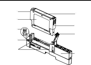
See the figures to familiarize yourself with major parts of the module, noting that the wiring base assembly is one of the following:
•1734-TB or 1734-TBS POINT I/O two-piece terminal base, which includes the 1734-RTB removable terminal block and 1734-MB mounting base
•1734-TOP or 1734-TOPS POINT I/O one-piece terminal base
The 1734-8CFG module is not compatible with 1734-TB3, 1734-TB3S, 1734-TOP3, and 1734-TOP3S terminal bases.
Publication 1734-IN038A-EN-P - October 2008

6 POINT I/O Module with 8 Configurable 24V DC Points
Module Locking
Mechanism
Module Wiring
Diagram
DIN Rail Locking
Screw (orange)
Mechanical
Keying (orange)
Interlocking Side
Pieces
ModuleStatus
NetworkStatus
NODE:
|
|
4 |
0 |
|
5 |
|
6 |
|
|
|
|
|
1 |
7 |
|
|
2 |
|
|
3 |
Mounting Base 
Slide-in Writable
Label
Insertable I/O
Module
RTB Removal
Handle
Removable Terminal
Block (RTB)
44713
Publication 1734-IN038A-EN-P - October 2008
POINT I/O Module with 8 Configurable 24V DC Points 7
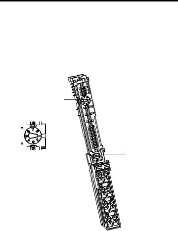
Module Locking
Mechanism Slide-in
Writable Label
Module Wiring
Diagram
Insertable
DIN Rail Locking I/O Module
Screw (orange)
Handle
Mechanical
Keying (orange)
Interlocking |
|
Side Pieces |
1734-TOP or |
|
1734-TOPS |
|
One-piece |
44714 |
Terminal Base |
|
with Screw or |
||
|
||
|
Spring Clamp |
Install the Mounting Base
Follow these steps to install the mounting base on the DIN rail.
1.Position the mounting base vertically above the installed units, for example, adapter, power supply, or existing module.
2.Slide the mounting base down so that the interlocking side pieces engage the adjacent module or adapter.
3.Press firmly to seat the mounting base on the DIN rail until the mounting base snaps into place.
4.To remove the mounting base from the DIN rail, remove the module, and use a small bladed screwdriver to rotate the base locking screw to a vertical position. This releases the locking mechanism. Then lift straight up to remove.
Publication 1734-IN038A-EN-P - October 2008
8 POINT I/O Module with 8 Configurable 24V DC Points
Install the I/O Module
The module can be installed before, or after base installation. Make sure the mounting base is correctly keyed before installing the module into the mounting base. In addition, make sure the mounting base locking screw is positioned horizontal referenced to the base.
1734-TB Base
Turn the keyswitch to align the number with the notch. Notch position 1 is shown.
44710 |
Be sure the DIN-rail |
locking screw is in the horizontal position.
44715
Publication 1734-IN038A-EN-P - October 2008
Loading...