


 Loading...
Installation Instructions
ArmorPoint 24V DC 16 Point Input and Output Modules, Series A
Catalog Numbers 1738-OB16E19M23, 1738-OB16EM12,
1738-OB16E25DS, 1738-IB16DM12
Topic |
Page |
|
|
|
|
|
|
Important User Information |
2 |
|
|
|
|
|
|
Environment and Enclosure |
3 |
|
|
|
|
|
|
Prevent Electrostatic Discharge |
3 |
|
|
|
|
|
|
About the Modules |
4 |
|
|
|
|
|
|
Mount the I/O Base |
5 |
|
|
|
|
|
|
Install the Digital Module |
7 |
|
|
|
|
|
|
Remove the Module From the Mounting Base |
8 |
|
|
|
|
|
|
Wire the Modules |
8 |
|
|
|
|
|
|
Communicate with Your Module |
10 |
|
|
|
|
|
|
Specifications |
14 |
|
|
|
|
|
|
|
|
|
|
|
|
|
|
2 ArmorPoint 24V DC 16 Point Input and Output Modules, Series A
Important User Information
Solid state equipment has operational characteristics differing from those of electromechanical equipment. Safety Guidelines for the Application, Installation and Maintenance of Solid State Controls (publication SGI-1.1 available from your local Rockwell Automation sales office or online at http://literature.rockwellautomation.com) describes some important differences between solid state equipment and hard-wired electromechanical devices. Because of this difference, and also because of the wide variety of uses for solid state equipment, all persons responsible for applying this equipment must satisfy themselves that each intended application of this equipment is acceptable.
In no event will Rockwell Automation, Inc. be responsible or liable for indirect or consequential damages resulting from the use or application of this equipment.
The examples and diagrams in this manual are included solely for illustrative purposes. Because of the many variables and requirements associated with any particular installation, Rockwell Automation, Inc. cannot assume responsibility or liability for actual use based on the examples and diagrams.
No patent liability is assumed by Rockwell Automation, Inc. with respect to use of information, circuits, equipment, or software described in this manual.
Reproduction of the contents of this manual, in whole or in part, without written permission of Rockwell Automation, Inc., is prohibited.
Throughout this manual, when necessary, we use notes to make you aware of safety considerations.
|
WARNING |
|
Identifies information about practices or circumstances that can cause an explosion |
||
|
|
|
|
|
|
|
|
|
|
|
in a hazardous environment, which may lead to personal injury or death, property |
|
|
|
|
|
damage, or economic loss. |
|
|
|
|
|
|
|
|
|
|
|
|
|
|
|
|
|
Identifies information that is critical for successful application and understanding of |
|
IMPORTANT |
||||
|
the product. |
||||
|
|
|
|
|
|
|
|
|
|
|
|
|
|
|
|
|
|
|
ATTENTION |
|
Identifies information about practices or circumstances that can lead to personal |
||
|
|
|
|
|
|
|
|
|
|
|
injury or death, property damage, or economic loss. Attentions help you to identify a |
|
|
|
|
|
hazard, avoid a hazard, and recognize the consequences. |
|
|
|
|
|
|
SHOCK HAZARD
Labels may be on or inside the equipment, for example, a drive or motor, to alert people that dangerous voltage may be present.
BURN HAZARD
Labels may be on or inside the equipment, for example, a drive or motor, to alert people that surfaces may reach dangerous temperatures.
Publication 1738-IN023B-EN-E - February 2010

|
|
|
ArmorPoint 24V DC 16 Point Input and Output Modules, Series A 3 |
|
|
|
|
Environment and Enclosure |
|||
|
|
|
|
|
|
|
This equipment is intended for use in overvoltage Category II applications (as |
ATTENTION |
|||
|
|
|
defined in IEC publication 60664-1), at altitudes up to 2000 meters (6562 ft) |
|
|
|
without derating. |
|
|
|
This equipment is considered Group 1, Class A industrial equipment according |
|
|
|
|
|
|
|
to IEC/CISPR Publication 11. Without appropriate precautions, there may be |
|
|
|
potential difficulties ensuring electromagnetic compatibility in other |
|
|
|
environments due to conducted as well as radiated disturbance. |
|
|
|
This equipment is supplied as enclosed equipment. It should not require |
|
|
|
additional system enclosure when used in locations consistent with the |
|
|
|
enclosure type ratings stated in the Specifications section of this publication. |
|
|
|
Subsequent sections of this publication may contain additional information |
|
|
|
regarding specific enclosure type ratings, beyond what this product provides, |
|
|
|
that are required to comply with certain product safety certifications. |
In addition to this publication, see:
•Industrial Automation Wiring and Grounding Guidelines, Allen-Bradley publication 1770-4.1, for additional installation requirements.
•NEMA Standards publication 250 and IEC publication 60529, as applicable, for explanations of the degrees of protection provided by different types of enclosure.
Prevent Electrostatic Discharge
ATTENTION |
This equipment is sensitive to electrostatic discharge, which can cause |
||
|
|
|
internal damage and affect normal operation. Follow these guidelines when |
|
|
|
you handle this equipment: |
|
|
|
• Touch a grounded object to discharge potential static. |
|
|
|
|
•Wear an approved grounding wriststrap.
•Do not touch connectors or pins on component boards.
•Do not touch circuit components inside the equipment.
•Use a static-safe workstation, if available.
•Store the equipment in appropriate static-safe packaging when not in use.
Publication 1738-IN023B-EN-E - February 2010
4 ArmorPoint 24V DC 16 Point Input and Output Modules, Series A
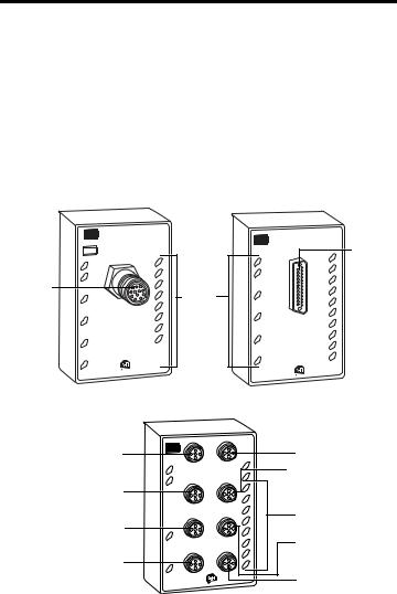
About the Modules
The ArmorPoint I/O family consists of modular I/O modules. The sealed IP67 housing of these modules requires no enclosure when used with IP67 certified cables. (Note that environmental requirements other than IP67 may require an additional appropriate housing.) I/O connectors are sealed DB25, M12 (micro) or M23 styles. The mounting base ships with the module. The 1738-OB16E19M23, 1738-OB16EM12, 1738-OB16E25DS and 1738-IB16DM12 are shown below.
1738-OB16E19M23, 1738-OB16EM12, 1738-OB16E25DS,
1738-IB16DM12 Modules
1738-OB16E19M23/A |
1738-OB16E25DS/A |
Connector
M23
FAULT
 0
0
1
 2
2
3
 4
4
5
 6
6
7
1738-OB16E19M23
24V DC In
MOD
NET
15 14 13 12 11 10  9
9  8
8
LED
Indicators
FAULT
 0
0
1
 2
2
3
 4
4
5
 6
6
7
1738-OB16E25DS |
|
24V DC |
Out |
|
MOD |
|
NET |
|
15 |
|
14 |
|
13 |
|
12 |
|
11 |
|
10 |
|
9 |
|
8 |
Connector
D-Shell
44353 |
44354 |
1738-OB16EM12/A and 1738-IB16DM12/A*
Connector M12-A
Connector M12-B
Connector M12-C
Connector M12-D
FAULT
 0
0  1
1  2
2  3
3
4  5
5  6
6
7
0-1 |
|
14-15 |
|
1738-OB16EM12/A |
MOD |
|
|
24V DC |
Out |
NET |
|
2-3 |
|
12-13 |
15 |
|
|
|
|
|
|
|
14 |
|
|
|
13 |
|
|
|
12 |
|
|
10-11 |
11 |
4-5 |
|
10 |
|
|
|
|
|
6-7 |
|
8-9 |
9 |
|
|
|
8 |
44355
Connector M12-H
 Connector M12-G
LED Indicators
Connector M12-F
Connector M12-E
* 1738-IB16DM12/A is represented here by the 1738-OB16EM12/A. They have identical connectors and LED indicators.
Publication 1738-IN023B-EN-E - February 2010

ArmorPoint 24V DC 16 Point Input and Output Modules, Series A 5
Mount the I/O Base
To mount the base on a wall or panel, use the screw holes provided in the base.
IMPORTANT |
The module must be mounted on a grounded metal mounting plate or other |
|
conductive surface.
Refer to the Drilling Dimensions illustration of the base with an adapter to help you mount the base.
Drilling Dimensions |
|
|
|
|
|
Adapter |
|
20.1 mm |
|
20.1 mm |
|
46.25 mm |
51.9 mm |
(0.8 in) |
51.9 mm |
(0.8 in) |
51.9 mm |
|
|
||||
(1.8 in) |
(2.0 in) |
|
(2.0 in) |
|
(2.0 in) |
56 mm |
|
|
|
|
|
(2.2 in) |
|
|
|
|
|
102 mm |
|
|
|
|
|
(4.02 in) |
|
|
|
|
|
43769
ATTENTION |
You can only use the 1738-EP24DC expansion power unit with the 1738 |
ArmorPoint I/O adapters.
Publication 1738-IN023B-EN-E - February 2010
6 ArmorPoint 24V DC 16 Point Input and Output Modules, Series A
ATTENTION |
To comply with the CE Low Voltage Directive (LVD), this equipment must be |
||
|
|
|
powered from a source compliant with the following: |
|
|
|
Safety Extra Low Voltage (SELV) or Protected Extra Low Voltage (PELV). |
|
|
|
|
|
|
|
|
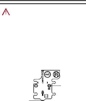
Install the mounting base as follows:
1.Lay out the required points as shown above in the drilling dimension drawing.
2.Drill the necessary holes for M4 (#8) machine or self-tapping screws.
3.Mount the base using M4 (#8) screws.
4.Ground the system using the ground lug connection. The ground lug connection is also a mounting hole.
Mounting Base
Keyswitch 


 Set to position 1 for the


1738 24V expansion power supply
Ground lug connection
Latching mechanism |
43675 |
|
Publication 1738-IN023B-EN-E - February 2010
Loading...