


1734-SSI
Table of contents
 Loading...
POINT I/O
Synchronous Serial
Interface Absolute
Encoder Module
1734-SSI
User Manual
Important User Information
SHOCK HAZARD
Solid state equipment has operational characteristics differing from those of
electromechanical equipment. Safety Guidelines for the Application,
Installation and Maintenance of Solid State Controls (Publication SGI-1.1
available from your local Rockwell Automation sales office or online at
http://literature.rockwellautomation.com/) describes some important
differences between solid state equipment and hard-wired electromechanical
devices. Because of this difference, and also because of the wide variety of
uses for solid state equipment, all persons responsible for applying this
equipment must satisfy themselves that each intended application of this
equipment is acceptable.
In no event will Rockwell Automation, Inc. be responsible or liable for indirect
or consequential damages resulting from the use or application of this
equipment.
The examples and diagrams in this manual are included solely for illustrative
purposes. Because of the many variables and requirements associated with any
particular installation, Rockwell Automation, Inc. cannot assume responsibility
or liability for actual use based on the examples and diagrams.
No patent liability is assumed by Rockwell Automation, Inc. with respect to
use of information, circuits, equipment, or software described in this manual.
Reproduction of the contents of this manual, in whole or in part, without
written permission of Rockwell Automation, Inc., is prohibited.
Throughout this manual, when neces sary, we u se notes t o make you awa re of
safety considerations.
WARNING
IMPORTANT
ATTENTION
BURN HAZARD
Identifies information about practices or circumstances
that can cause an explosion in a hazardous environment,
which may lead to personal injury or death, property
damage, or economic loss.
Identifies information that is critical for successful
application and understanding of the product.
Identifies information about practices or circumstances
that can lead to personal injury or death, property
damage, or economic loss. Attentions help you:
• identify a hazard
• avoid a hazard
• recognize the consequence
Labels may be located on or inside the equipment (for
example, drive or motor) to alert people that dangerous
voltage may be present.
Labels may be located on or inside the equipment (for
example, drive or motor) to alert people that surfaces may
be dangerous temperatures.
Allen-Bradley, ControlLogix, POINT I/O, POINTBus, RSLinx, RSLogix 5000, RS Networx, and RSNetworx for DeviceNet are
trademarks of Rockwell Automation, Inc.
Trademarks not belonging to Rockwell Automation are property of their respective companies.

Summary of Changes
This publication contains new and revised information not in the last
release.
New and Revised Information
See the table for a summary of the major changes in this manual.
Chapter Change
Chapter 4 Set and Operate
Your Module
Updated section on operation of the Data Latch and
Comparator features.
Chapter 5 Diagnose Problems
Appendix A Configure Modules
in RSLogix 5000
Software
Added a column on recommended actions in all of the
troubleshooting charts.
Updated procedures on how to use the Watch Position
dialog.
Change Bars
W e marked with change bars (as shown with this paragraph) the areas
in this manual that are different from previous editions and indicate
the addition of new or revised information.
1 Publication 1734-UM007D-EN-P - December 2005

Summary of Changes 2
Notes:
Publication 1734-UM007D-EN-P - December 20 05

Table of Contents
Preface
Install the Module
Configure the Module
Purpose of This Manual. . . . . . . . . . . . . . . . . . . . . . . Preface-1
Who Should Use This Manual . . . . . . . . . . . . . . . . . . Preface-1
Related Products and Documentation. . . . . . . . . . . . . Preface-2
Chapter 1
About This Chapter. . . . . . . . . . . . . . . . . . . . . . . . . . . . . . 1-1
About the Module. . . . . . . . . . . . . . . . . . . . . . . . . . . . . . . 1-1
Install the Mounting Base . . . . . . . . . . . . . . . . . . . . . . . . . 1-2
Install a Module . . . . . . . . . . . . . . . . . . . . . . . . . . . . . . . . 1-3
Install the Removable Terminal Block . . . . . . . . . . . . . . . . 1-5
Remove a Mounting Base . . . . . . . . . . . . . . . . . . . . . . . . . 1-6
Wire the Module. . . . . . . . . . . . . . . . . . . . . . . . . . . . . . . . 1-7
Chapter 2
About This Chapter. . . . . . . . . . . . . . . . . . . . . . . . . . . . . . 2-1
Add the Adapter to Your Network. . . . . . . . . . . . . . . . . . . 2-1
Add I/O Modules to Your Network . . . . . . . . . . . . . . . . . . 2-2
Set the Encoder’s Parameters . . . . . . . . . . . . . . . . . . . . . . . 2-3
Check I/O Status and View the EDS File . . . . . . . . . . . . . . 2-5
Communicate with Your Module
Set and Operate Your Module
Diagnose Problems
Chapter 3
About This Chapter. . . . . . . . . . . . . . . . . . . . . . . . . . . . . . 3-1
About Communications. . . . . . . . . . . . . . . . . . . . . . . . . . . 3-1
Communicate Real-time Information . . . . . . . . . . . . . . . . . 3-3
Operating Modes . . . . . . . . . . . . . . . . . . . . . . . . . . . . . . . 3-5
Chapter 4
About This Chapter. . . . . . . . . . . . . . . . . . . . . . . . . . . . . . 4-1
Module Configuration Value Definitions. . . . . . . . . . . . . . . 4-1
Operation of the Data Latch and Comparator Features . . . . 4-4
Data Latch. . . . . . . . . . . . . . . . . . . . . . . . . . . . . . . . . . 4-4
Comparators 1 and 2 . . . . . . . . . . . . . . . . . . . . . . . . . . 4-5
Other Module Features . . . . . . . . . . . . . . . . . . . . . . . . . . . 4-6
Example of Using the 1734-SSI Module
with a 24-bit SSI Sensor. . . . . . . . . . . . . . . . . . . . . . . . . . . 4-7
Chapter 5
About This Chapter. . . . . . . . . . . . . . . . . . . . . . . . . . . . . . 5-1
Use the Indicators for Troubleshooting . . . . . . . . . . . . . . . 5-1
1 Publication 1734-UM007D-EN-P - December 2005

Table of Contents 2
Configure Modules in RSLogix
5000 Software
Index
Appendix A
About This Appendix . . . . . . . . . . . . . . . . . . . . . . . . . . . . A-1
Understand Data, Connection, and Communication Formats A-1
Configure Your Module. . . . . . . . . . . . . . . . . . . . . . . . . . . A-2
Use the Help Button . . . . . . . . . . . . . . . . . . . . . . . . . . . . . A-2
Work with the Feedback Dialog . . . . . . . . . . . . . . . . . . . . A-3
Work with the Conversion Dialog . . . . . . . . . . . . . . . . . . . A-4
Work with the Input Registration Dialog . . . . . . . . . . . . . . A-6
Work with the Watch Position Dialog . . . . . . . . . . . . . . . . A-7
Publication 1734-UM007D-EN-P - December 2005
Preface
Purpose of This Manual
Who Should Use This Manual
Read this manual for information about how to install, configure, and
troubleshoot your module.
For This Information See
Install the Module Chapter 1
Configure the Module Chapter 2
Communicate with Your Module Chapter 3
Operate Your Module Chapter 4
Diagnose Problems Chapter 5
Configure Modules in RSLogix 5000 Appendix A
You must be able to use RSNetWorx software or similar co nfiguration
software to set up and calibrate these modules. You must have the
capability to download and use electronic data sheet files.
In this manual, we assume you know how to do perform these tasks.
If you do not, refer to your software user manuals or online help
before attempting to use these modules.
1 Publication 1734-UM007D-EN-P - December 2005

2 Preface
Related Products and Documentation
For specification, safety approval, and other information, refer to
POINT I/O Synchronous Serial Interface Absolute Encode r Mo dule
Installation Instructions, publication 1734-IN581.
For related 1734 products and documentation, see the table. Many of
these publications are available online from
http://literature.rockwellautomation.com
Description Cat. No. Publication
Analog Input Modules
Installation Instructions
Analog Output Modules
Installation Instructions
DeviceNet Communication Interface
Installation Instructions
Field Potential Distributor
Installation Instructions
POINT I/O 24V dc Expansion Power Supply
Installation Instructions
POINT I/O Selection Guide 1734 series 1734-SG001
Protected Output Module s
Installation Instructions
Relay Output Modules
Installation Instructions
Sink Input Modules
Installation Instructions
Source Output Modules
Installation Instructions
Very High-speed Counter Modules
Installation Instructions
Wiring Base Assembly
Installation Instructions
1734-IE2C
17340IE2V
1734-OE2C
1734-OE2V
1734-PDN 1734-IN057
1734-FPD 1734-IN059
1734-EP24DC 1734-IN058
1734-OB2E
1734-OB4E
1734-OB8E
1734-OW2
1734-OW4
1734-IB2
1734-IB4
1734-IB8
1734-IV2
1734-IV4
1734-IV8
1734-VHSC5
1734-VHSC24
1734-TB
1734-TBS
1734-IN027
1734-IN002
1734-IN056
1734-IN055
1734-IN051
1734-IN052
1734-IN003
1734-IN511
Publication 1734-UM007D-EN-P - December 20 05
Wiring Base Assembly
Installation Instructions
1734-TB3
1734-TB3S
1734-IN013
Install the Module
M
B)
Chapter
1
About This Chapter
About the Module
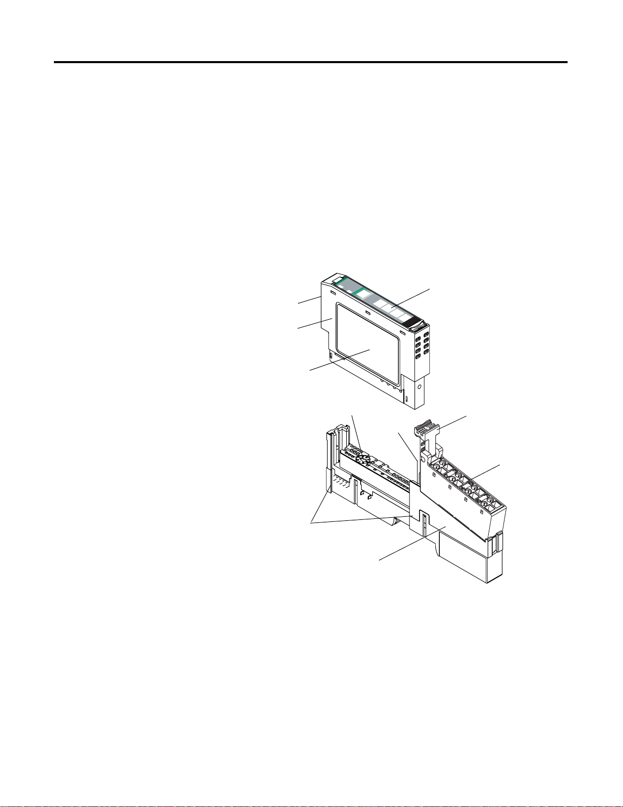
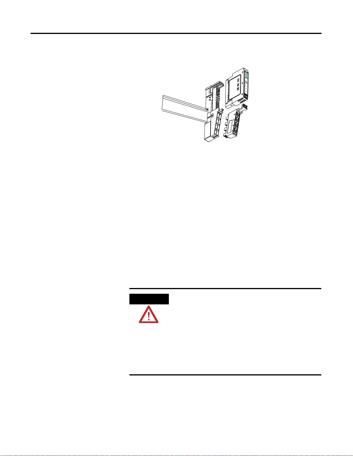
Read this chapter to learn about how to install, wire, and remove the
1734-SSI module.
The 1734-SSI module collects serial data from industrial
absolute-position encoding sensors that use a standard SSI protocol.
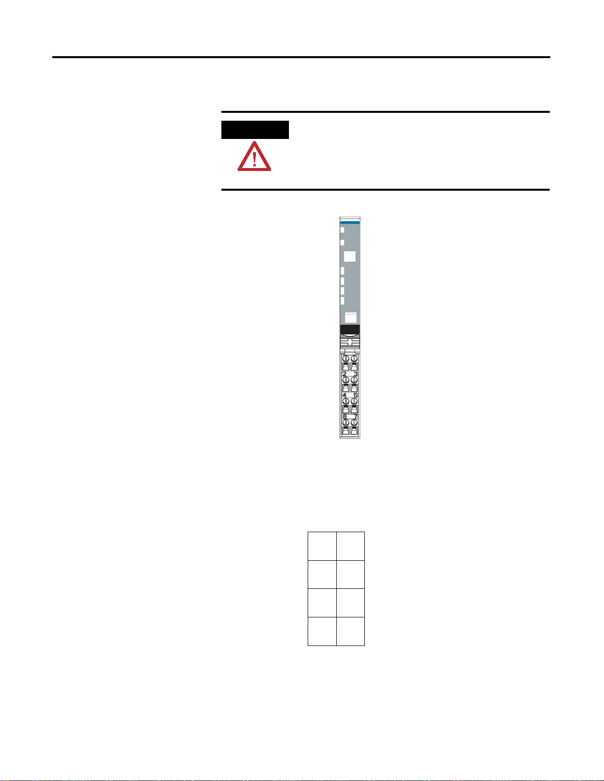
odule Locking Mechanism
Insertable I/O Module
Module Wiring Diagram
Module
Status
1
Network
Status
NODE:
24VDC
Source
Mechanical Keying
(Orange)
DIN Rail Locking Screw
Output
0
Slide-in Writable Label
1
2
3
1734
OB4E
(Orange)
RTB Removing Handle
Removable Terminal Block (RT
Interlocking Side Pieces
Mounting Base
43122
Insert the module into a POINT I/O terminal base that provides
common power, communication, and wiring connections for the SSI
sensors. Use this Series C module with the following.
• ControlNet adapter
with RSLogix 5000 software, version 11 or later
• DeviceNet adapter
• EtherNet/IP adapter
with RSLogix 5000 software, version 11 or later
• PROFIBUS adapter
1 Publication 1734-UM007D-EN-P - December 2005

1-2 Install the Module
Install the Mounting Base
The wiring base assembly (1734-TB or 1734-TBS) consists of a
mounting base (1734-MB) and a removable terminal block (1734-RTB
or 1734-RTBS). You can install the assembly, or just the mounting
base. To install the mounting base/wiring base assembly on the DIN
rail, proceed as follows.
ATTENTION
POINT I/O is grounded through the DIN rail to
chassis ground. Use zinc-plated yellow-chromate
steel DIN rail to assure proper grounding. The use of
other DIN rail material (such as aluminum and
plastic) that can corrode, oxidize, or are poor
conductors, can result in improper or intermittent
grounding.
Secure DIN rail to mounting surface approximately
every 200 mm (7.8 in.).
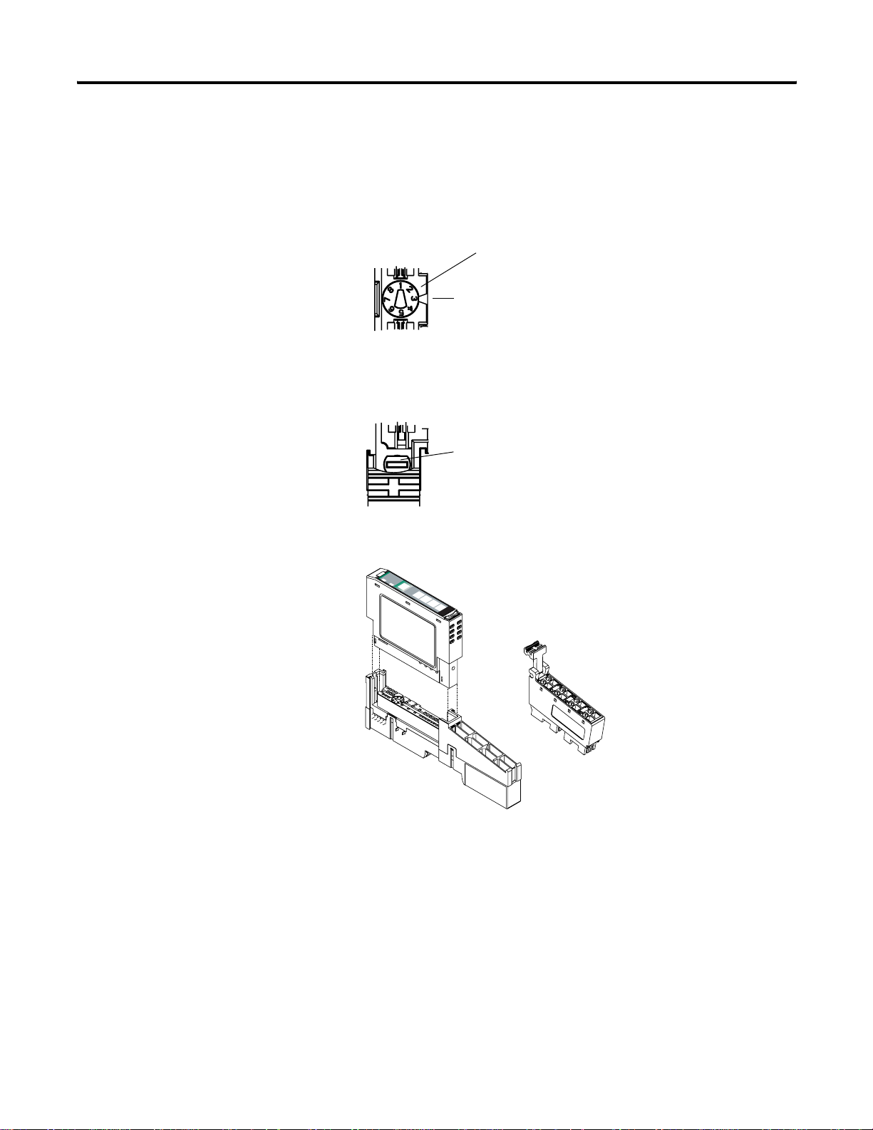
1. Position the mounting base/wiring base assembly vertically
above the installed units (adapter, power supply, or existing
module).
2. Slide the mounting base down, allowing the interlocki ng side
pieces to engage the adjacent module or adapter.
Slide the mounting base to allow the
interlocking side pieces to engage the
adjacent module or adapter.
31586
Publication 1734-UM007D-EN-P - December 20 05
Install the Module 1-3
3. Press firmly to seat the mounting base on the DIN rail, noting
that the mounting base snaps into place.
Module
Status
Network
Status
NODE:
24VDC
Source
Output
0
1
2
3
1734
OB4E
44013
4. To remove the mounting base from the DIN rail, remove any
installed module (and any module immediately to the right), and
use a small-bladed screwdriver to rotate the DIN rail locking
screw to a vertical position.
Install a Module
This releases the locking mechanism.
5. Lift straight up to remove the mounting base.
6. Repeat this procedure for the next mounting base assembly.
Install the module before or after base installation. Make sure that the
mounting base is correctly keyed before installing the module into the
mounting base. In addition, make sure the mounting base locking
screw is horizontal referenced to the base.
WARNING
When you insert or remove the module while
backplane power is on, an electrical arc can occur.
This could cause an explosion in hazardous l ocation
installations.
Be sure that power is removed or the area is
nonhazardous before proceeding. Repeated electrical
arcing causes excessive wear to contacts on both the
module and its mating connector. W orn contacts may
create electrical resistance that can affect module
operation.
Publication 1734-UM007D-EN-P - December 2005
1-4 Install the Module
1. Using a bladed screwdriver, rotate the keyswitch on the
mounting base clockwise till the number requi red for the type of
module being installed aligns with the notch in the base.
1734-SSI - Position 2
T urn the keyswitch to alig n
the number with the notch.
Notch
(Position 3 Shown)
44009
2. Make sure the DIN-rail locking screw is in the horizontal
position, noting that you cannot insert the module if the locking
mechanism is unlocked.
Make sure the DIN-rail
locking screw is in the
horizontal position.
44101
3. Insert the module straight down into the mounting base and
press to secure, locking the module into pl ace .
Module
Status
Network
Status
NODE:
24VDC
Source
Output
0
1
2
3
1734
OB4E
44012
Publication 1734-UM007D-EN-P - December 20 05
Install the Module 1-5
Install the Removable Terminal Block
A removable terminal block comes with your mounting base
assembly.
To remove, pull up on the RTB handle. This lets you remove and
replace the base as necessary without removing any of the wiring.
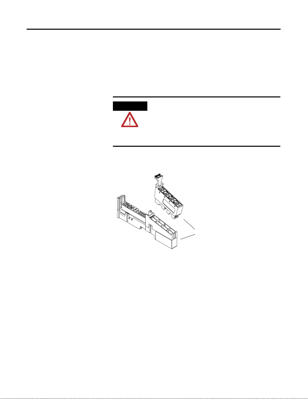
To reinsert the removable terminal block, proceed as follows.
WARNING
When you connect or disconnect the removable
terminal block (RTB) with field-side power applied,
an electrical arc can occur. This could cause an
explosion in hazardous location installations.
Be sure that power is removed or the area is
nonhazardous before proceeding.
1. Insert the RTB end opposite the handle into the base unit,
noting that the end has a curved section that engages with the
mounting base.
44011
Hook the RTB end into
the mounting base end,
and rotate until it locks
into place.
2. Rotate the terminal block into the mounting base until it locks
itself in place.
3. If an I/O module is installed, snap the RTB handle into place on
the module.
Publication 1734-UM007D-EN-P - December 2005
1-6 Install the Module
Remove a Mounting Base
To remove a mounting base, you must remove any installed module,
and remove the removable terminal block (if wired).
1. Unlatch the RTB handle on the I/O module.
2. Pull on the RTB handle to remove the removable terminal block.
WARNING
When you connect or disconnect the removable
terminal block (RTB) with field-side power applied,
an electrical arc can occur. This could cause an
explosion in hazardous location installations.
Be sure that power is removed or the area is
nonhazardous before proceeding.
3. Press in on the module lock on the top of the module, and pull
up on the I/O module to remove from the base.
4. Remove the module to the right of the base you are removing.
The interlocking portion of the base sits under the adjacent
module.
WARNING
When you insert or remove the module while
backplane power is on, an electrical arc can occur.
This could cause an explosion in hazardous location
installations.
Be sure that power is removed or the area is
nonhazardous before proceeding. Repeated electrical
arcing causes excessive wear to contacts on both the
module and its mating connector . W orn contacts may
create electrical resistance that can affect module
operation.
5. Use a small-bladed screwdriver to rotate the orange DIN-rail
locking screw on the mounting base to a vertical position,
releasing the locking mechanism.
6. Lift the mounting base straight up to remove.
Publication 1734-UM007D-EN-P - December 20 05
Install the Module 1-7
Wire the Module
Read this section for information about wiring the module.
WARNING
If you connect or disconnect wiring while the
field-side power is on, an electrical arc can occur.
This could cause an explosion in hazardous l ocation
installations. Be sure that power is removed or the
area is nonhazardous before proceeding.
Run
Up
Down
Comp
D+
Module
Status
Network
Status
NODE:
RUN
UP
DOWN
COMP
I1
I1
1734
SSI
D-
Module Status
Network Status
V+
Shield
C+
V-
I1
C-
43123
D = Data I1 = Digital Sourcing Input 1
C = Clock V = SSI Sensor
1
0
D+
D-
23
V+
C+
V-
I1
7
C-
43124
45
Shield
6
D = Data I1 = Digital Sourcing Input 1
C = Clock V = SSI Sensor
Publication 1734-UM007D-EN-P - December 2005
1-8 Install the Module
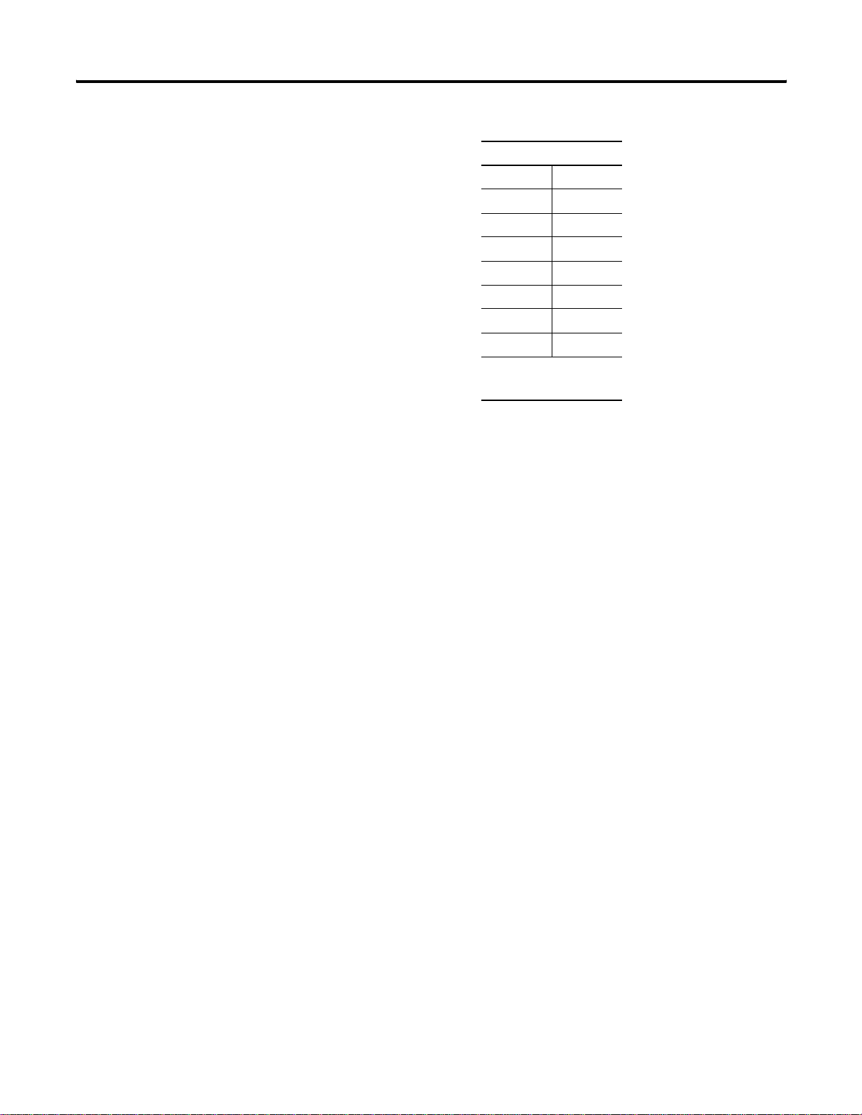
Module Terminations
0D+
1D-
1
1
2V+
3V4 Shield
5I1
6C+
7C-
1 D and C are RS422-type
differential pairs.
1
1
Publication 1734-UM007D-EN-P - December 20 05
Loading...