


 Loading...
User Manual
ControlLogix Enhanced Redundancy System
Catalog Numbers 1756-RM, 1756-RMXT, 1756-RM2, 1756-RM2XT
Important User Information
Solid-state equipment has operational characteristics differing from those of electromechanical equipment. Safety Guidelines for the Application, Installation and Maintenance of Solid State Controls (publication SGI-1.1 available from your local Rockwell Automation sales office or online at http://www.rockwellautomation.com/literature/) describes some important differences between solid-state equipment and hard-wired electromechanical devices. Because of this difference, and also because of the wide variety of uses for solid-state equipment, all persons responsible for applying this equipment must satisfy themselves that each intended application of this equipment is acceptable.
In no event will Rockwell Automation, Inc. be responsible or liable for indirect or consequential damages resulting from the use or application of this equipment.
The examples and diagrams in this manual are included solely for illustrative purposes. Because of the many variables and requirements associated with any particular installation, Rockwell Automation, Inc. cannot assume responsibility or liability for actual use based on the examples and diagrams.
No patent liability is assumed by Rockwell Automation, Inc. with respect to use of information, circuits, equipment, or software described in this manual.
Reproduction of the contents of this manual, in whole or in part, without written permission of Rockwell Automation, Inc., is prohibited.
Throughout this manual, when necessary, we use notes to make you aware of safety considerations.
WARNING: Identifies information about practices or circumstances that can cause an explosion in a hazardous environment, which may lead to personal injury or death, property damage, or economic loss.
ATTENTION: Identifies information about practices or circumstances that can lead to personal injury or death, property damage, or economic loss. Attentions help you identify a hazard, avoid a hazard, and recognize the consequence.
SHOCK HAZARD: Labels may be on or inside the equipment, for example, a drive or motor, to alert people that dangerous voltage may be present.
BURN HAZARD: Labels may be on or inside the equipment, for example, a drive or motor, to alert people that surfaces may reach dangerous temperatures.
IMPORTANT Identifies information that is critical for successful application and understanding of the product.
Allen-Bradley, ControlFLASH, ControlLogix, FactoryTalk, PanelView, PhaseManager, Rockwell Software, Rockwell Automation, RSLinx, RSLogix, RSNetWorx, VersaView, RSView32, Logix5000, ControlLogix-XT, Integrated Architecture, Stratix 8000, PowerFlex, POINT I/O are trademarks of Rockwell Automation, Inc.
Trademarks not belonging to Rockwell Automation are property of their respective companies.

Summary of Changes
New and Updated
Information
This publication contains new and updated information. Changes throughout this revision are marked by change bars, as shown to the right of this paragraph.
This table contains the changes made to this publication revision.
Table 1 - New and Updated Information
Topic |
Page |
|
|
This publication includes the addition of the 1756-RM2/A and 1756-RM2XT modules. |
|
1756-RM2/A or 1756-RM2XT modules can only be used with other 1756-RM2/A or |
|
1756-RM2XT modules. You cannot mix 1756-RM2/A and 1756-RM2XT modules with |
|
1756-RM/A, 1756-RM/B or 1756-RMXT modules. |
|
|
|
References throughout the manual to specific redundancy module catalog numbers |
|
have been replaced with ‘redundancy module.’ |
|
|
|
This manual includes SIL2 application information. |
13 |
|
|
Features of enhanced redundancy system using 1756-RM2/A module. |
16 |
|
|
Replace 1756-RM/B redundancy modules with 1756-RM2/A redundancy modules |
20 |
without initiating a switchover. |
|
Fiber channels will experience a delay during a switchover, but will remain synched. |
|
|
|
1756-RM2/A restrictions. |
22 |
|
|
Added 1756-RM2/A and 1756-RM2XT information; important revision information |
24 |
changes for the 1756-RM2/A and 1756-RM2XT modules. |
|
|
|
The revision has been updated wherever the 1756-L7x controller appears in this manual |
27 |
to 19.053. |
|
|
|
Added new firmware bundles 20.054_kit1, 19.053_kit1, and 19.081_kit1. |
49 |
|
|
Use newest version of RMCT when using 1756-RM2/A redundancy module. |
54 |
|
|
Added the 1756-RM2/A and 1756-RM2XT modules and installation requirements. |
57 |
|
|
Added the statement: 1756-RM2/A or 1756-RM2XT modules can only be used with |
57 |
other 1756-RM2/A or 1756-RM2XT modules. You cannot mix 1756-RM2/A and 1756- |
|
RM2XT modules with 1756-RM/A, 1756-RM/B or 1756-RMXT modules. |
|
|
|
Environment and Enclosure change. |
58 |
|
|
Small form-factor pluggable warning. |
59 |
|
|
Added new 1756-RM2/A and 1756-RM2XT module graphics. |
61 |
|
|
Added installation instructions. |
62 |
|
|
Added information about connecting fiber-optic cable to redundancy channels and |
64 |
using redundant fiber cabling. |
|
|
|
Updated fiber-optic cable information for new redundancy modules. |
67 |
|
|
Updated the graphics for the redundant fiber-optic cable. |
68 |
|
|
Updated the graphics for the redundant fiber-optic cable. |
69 |
|
|
Using dual fiber ports with the 1756-RM2 redundancy modules |
138 |
|
|
Crossload times when using a 1756-L7x and a 1756-RM2/A redundancy module. |
151 |
|
|
Using a 1756-L7x controller with a 1756-RM2/A redundancy module. |
152 |
|
|
Status indicators for 1756-RM2/A and 1756-RM2XT. |
200 |
|
|
1756-RM2/A and 1756-RM2XT status indicators. |
227 |
|
|
CH1 status indicator. |
229 |
|
|
CH2 status indicator. |
229 |
|
|
Rockwell Automation Publication 1756-UM535D-EN-P - November 2012 |
3 |

Summary of Changes
Table 1 - New and Updated Information
Topic |
Page |
|
|
SFP error message. |
230 |
|
|
Added missing Module Status Display descriptions for the 1756-RM/A and 1756-RM/B |
231 |
modules. |
|
|
|
Replace 1756-RM/B redundancy modules with 1756-RM2/A redundancy modules |
264 |
without initiating a switchover. |
|
|
|
4 |
Rockwell Automation Publication 1756-UM535D-EN-P - November 2012 |

Table of Contents
Preface
About Enhanced Redundancy
Systems
Design an Enhanced Redundancy
System
Additional Resources . . . . . . . . . . . . . . . . . . . . . . . . . . . . . . . . . . . . . . . . . . . . . 13
Chapter 1
Features of the ControlLogix Enhanced Redundancy System . . . . . . . . 16
Enhanced Redundancy System Components . . . . . . . . . . . . . . . . . . . . . . . 17
I/O Modules in Enhanced Redundancy Systems . . . . . . . . . . . . . . . . 18
Enhanced Redundancy System Operations . . . . . . . . . . . . . . . . . . . . . . . . . 19
System Qualification and Synchronization . . . . . . . . . . . . . . . . . . . . . 19
Switchovers . . . . . . . . . . . . . . . . . . . . . . . . . . . . . . . . . . . . . . . . . . . . . . . . . . 20
Restrictions. . . . . . . . . . . . . . . . . . . . . . . . . . . . . . . . . . . . . . . . . . . . . . . . . . . . . . 22
Chapter 2
Components of an Enhanced Redundancy System . . . . . . . . . . . . . . . . . . 24 Redundant Chassis . . . . . . . . . . . . . . . . . . . . . . . . . . . . . . . . . . . . . . . . . . . 28 Controllers in Redundant Chassis . . . . . . . . . . . . . . . . . . . . . . . . . . . . . 29 Redundancy Modules in Redundant Chassis. . . . . . . . . . . . . . . . . . . . 31 Communication Modules in Redundant Chassis. . . . . . . . . . . . . . . . 32 Power Supplies and Redundant Power Supplies in Enhanced Redundancy Systems . . . . . . . . . . . . . . . . . . . . . . . . . . . . . . . . . . . . . . . . . 34
EtherNet/IP Networks with Redundant Systems . . . . . . . . . . . . . . . . . . . 35 EtherNet/IP Network Features in an Enhanced
Redundancy System, Revision 19.052 or Later . . . . . . . . . . . . . . . . . . 35 IP Address Swapping . . . . . . . . . . . . . . . . . . . . . . . . . . . . . . . . . . . . . . . . . 36 Unicast Functionality. . . . . . . . . . . . . . . . . . . . . . . . . . . . . . . . . . . . . . . . . 36 Possible Communication Delays on EtherNet/IP Networks . . . . . 36 ControlNet Networks with Redundant Systems . . . . . . . . . . . . . . . . . . . . 38 ControlNet Network Requirements . . . . . . . . . . . . . . . . . . . . . . . . . . . 38 Redundant ControlNet Media . . . . . . . . . . . . . . . . . . . . . . . . . . . . . . . . 41 Other Communication Networks . . . . . . . . . . . . . . . . . . . . . . . . . . . . . . . . . 42 I/O Placement . . . . . . . . . . . . . . . . . . . . . . . . . . . . . . . . . . . . . . . . . . . . . . . . . . . 44 1715 Redundant I/O Systems . . . . . . . . . . . . . . . . . . . . . . . . . . . . . . . . . 44 Using HMI. . . . . . . . . . . . . . . . . . . . . . . . . . . . . . . . . . . . . . . . . . . . . . . . . . . . . . 46 HMI Connected via an EtherNet/IP Network. . . . . . . . . . . . . . . . . . 46 HMI Connected via a ControlNet Network. . . . . . . . . . . . . . . . . . . . 47 Firmware Requirements . . . . . . . . . . . . . . . . . . . . . . . . . . . . . . . . . . . . . . . . . . 49 Software Requirements . . . . . . . . . . . . . . . . . . . . . . . . . . . . . . . . . . . . . . . . . . . 49 Required Software. . . . . . . . . . . . . . . . . . . . . . . . . . . . . . . . . . . . . . . . . . . . 49 Optional Software. . . . . . . . . . . . . . . . . . . . . . . . . . . . . . . . . . . . . . . . . . . . 50
|
Chapter 3 |
|
Install the Enhanced Redundancy |
Before You Begin . . . . . . . . . . . . . . . . . . . . . . . . . . . . . . . . . . . . . . . . . . . . . . . . |
51 |
System |
Enhanced Redundancy System Quick Start . . . . . . . . . . . . . . . . . . . . . |
51 |
|
Install an Enhanced Redundancy System . . . . . . . . . . . . . . . . . . . . . . . . . . . |
53 |
|
Step 1: Install the Software. . . . . . . . . . . . . . . . . . . . . . . . . . . . . . . . . . . . . . . . |
53 |
Rockwell Automation Publication 1756-UM535D-EN-P - November 2012 |
5 |

Table of Contents
Install the Software . . . . . . . . . . . . . . . . . . . . . . . . . . . . . . . . . . . . . . . . . . . 53
Add the EDS Files . . . . . . . . . . . . . . . . . . . . . . . . . . . . . . . . . . . . . . . . . . . . 54
Step 2: Install the Hardware . . . . . . . . . . . . . . . . . . . . . . . . . . . . . . . . . . . . . . . 54
Install the First Chassis and its Components . . . . . . . . . . . . . . . . . . . . 54
Install the Chassis and Power Supply . . . . . . . . . . . . . . . . . . . . . . . . . . . 55
Install the Communication Modules . . . . . . . . . . . . . . . . . . . . . . . . . . . 56
Install a Controller. . . . . . . . . . . . . . . . . . . . . . . . . . . . . . . . . . . . . . . . . . . . 56
Install the Redundancy Module . . . . . . . . . . . . . . . . . . . . . . . . . . . . . . . . 57
Environment and Enclosure . . . . . . . . . . . . . . . . . . . . . . . . . . . . . . . . . . . 58
Prevent Electrostatic Discharge . . . . . . . . . . . . . . . . . . . . . . . . . . . . . . . . 58
Removal and Insertion Under Power (RIUP) . . . . . . . . . . . . . . . . . . . 58
European Hazardous Location Approval . . . . . . . . . . . . . . . . . . . . . 58
Safety-related Programmable Electronic Systems . . . . . . . . . . . . . . . . 59
Optical Ports . . . . . . . . . . . . . . . . . . . . . . . . . . . . . . . . . . . . . . . . . . . . . . . . . 59
Small Form-factor Pluggable. . . . . . . . . . . . . . . . . . . . . . . . . . . . . . . . . . . 59
North American Hazardous Location Approval. . . . . . . . . . . . . . . . . 60
Laser Radiation Ports . . . . . . . . . . . . . . . . . . . . . . . . . . . . . . . . . . . . . . . . . 60
Install the Second Chassis . . . . . . . . . . . . . . . . . . . . . . . . . . . . . . . . . . . . . 63
Step 3: Connect the Redundancy Modules via a Fiber-optic Cable. . . . 63
Connect the Fiber-optic Communication Cable to Redundant
Channels. . . . . . . . . . . . . . . . . . . . . . . . . . . . . . . . . . . . . . . . . . . . . . . . . . . . . 65
Connect the Fiber-optic Communication Cable to
Single Channels . . . . . . . . . . . . . . . . . . . . . . . . . . . . . . . . . . . . . . . . . . . . . . 66
Fiber-optic Cable . . . . . . . . . . . . . . . . . . . . . . . . . . . . . . . . . . . . . . . . . . . . . 67
Step 4: Update Redundant Chassis Firmware . . . . . . . . . . . . . . . . . . . . . . . 67
Upgrade the Firmware in the First Chassis . . . . . . . . . . . . . . . . . . . . . . 68
Upgrade the Firmware in the Second Chassis . . . . . . . . . . . . . . . . . . . 71
Step 5: Designate the Primary and Secondary Chassis. . . . . . . . . . . . . . . . 71
After Designation. . . . . . . . . . . . . . . . . . . . . . . . . . . . . . . . . . . . . . . . . . . . . 73
Conversion from a Nonredundant to a Redundant System . . . . . . . 73
Qualification Status via the RMCT . . . . . . . . . . . . . . . . . . . . . . . . . . . . 74
Reset the Redundancy Module. . . . . . . . . . . . . . . . . . . . . . . . . . . . . . . . . 75
Remove or Replace the Redundancy Module . . . . . . . . . . . . . . . . . . . . 75
Chapter 4
Configure the EtherNet/IP Network Requested Packet Interval . . . . . . . . . . . . . . . . . . . . . . . . . . . . . . . . . . . . . . . . . 77
CPU Usage . . . . . . . . . . . . . . . . . . . . . . . . . . . . . . . . . . . . . . . . . . . . . . . . . . 77
Use IP Address Swapping . . . . . . . . . . . . . . . . . . . . . . . . . . . . . . . . . . . . . . . . . 77
Static versus Dynamic IP Addresses . . . . . . . . . . . . . . . . . . . . . . . . . . . . 80
Reset the IP Address for an EtherNet/IP Communication
Module . . . . . . . . . . . . . . . . . . . . . . . . . . . . . . . . . . . . . . . . . . . . . . . . . . . . . . 80
Use CIP Sync . . . . . . . . . . . . . . . . . . . . . . . . . . . . . . . . . . . . . . . . . . . . . . . . . . . . 81
Use Produce/Consume Connections . . . . . . . . . . . . . . . . . . . . . . . . . . . . . . 84
Configure EtherNet/IP Communication Modules in a
Redundant System. . . . . . . . . . . . . . . . . . . . . . . . . . . . . . . . . . . . . . . . . . . . 85
Before You Begin . . . . . . . . . . . . . . . . . . . . . . . . . . . . . . . . . . . . . . . . . . . . . 85
6 |
Rockwell Automation Publication 1756-UM535D-EN-P - November 2012 |

Table of Contents
Options for Setting the IP Addresses of EtherNet/IP
Communication Modules. . . . . . . . . . . . . . . . . . . . . . . . . . . . . . . . . . . . . 86
Half/Full Duplex Settings. . . . . . . . . . . . . . . . . . . . . . . . . . . . . . . . . . . . . 86
Use An Enhanced Redundancy System in a Device-level
Ring Topology . . . . . . . . . . . . . . . . . . . . . . . . . . . . . . . . . . . . . . . . . . . . . . . 87
Chapter 5
Configure the ControlNet Network Produce/Consume Connections . . . . . . . . . . . . . . . . . . . . . . . . . . . . . . . . . . 93 Network Update Time . . . . . . . . . . . . . . . . . . . . . . . . . . . . . . . . . . . . . . . . . . . 95 NUTs with Multiple ControlNet Networks. . . . . . . . . . . . . . . . . . . . 95 Use a Scheduled or Unscheduled Network . . . . . . . . . . . . . . . . . . . . . . . . . 97 Use a Scheduled Network . . . . . . . . . . . . . . . . . . . . . . . . . . . . . . . . . . . . . 97 Use an Unscheduled Network . . . . . . . . . . . . . . . . . . . . . . . . . . . . . . . . . 97 Add Remote ControlNet Modules While Online . . . . . . . . . . . . . . . 98 Schedule a New Network . . . . . . . . . . . . . . . . . . . . . . . . . . . . . . . . . . . . . . . . . 98 Update an Existing Scheduled Network. . . . . . . . . . . . . . . . . . . . . . . . . . . 100 Check the Network Keeper States . . . . . . . . . . . . . . . . . . . . . . . . . . . . . . . . 101 Save the Project for Each Primary Controller . . . . . . . . . . . . . . . . . . 102 Automatic Keeper Crossloads . . . . . . . . . . . . . . . . . . . . . . . . . . . . . . . . 102
Chapter 6
Configure the Redundancy Modules About the Redundancy Module Configuration Tool (RMCT) . . . . . 105
Determine if Further Configuration is Required . . . . . . . . . . . . . . . . . . . 106
Use the RMCT . . . . . . . . . . . . . . . . . . . . . . . . . . . . . . . . . . . . . . . . . . . . . . . . . 107
Identify the RMCT Version. . . . . . . . . . . . . . . . . . . . . . . . . . . . . . . . . . 109
Update the RMCT Version . . . . . . . . . . . . . . . . . . . . . . . . . . . . . . . . . . 110
Module Info Tab. . . . . . . . . . . . . . . . . . . . . . . . . . . . . . . . . . . . . . . . . . . . . . . . 111
Configuration Tab . . . . . . . . . . . . . . . . . . . . . . . . . . . . . . . . . . . . . . . . . . . . . . 113
Auto-Synchronization . . . . . . . . . . . . . . . . . . . . . . . . . . . . . . . . . . . . . . . 114
Chassis ID . . . . . . . . . . . . . . . . . . . . . . . . . . . . . . . . . . . . . . . . . . . . . . . . . . 115
Enable User Program Control . . . . . . . . . . . . . . . . . . . . . . . . . . . . . . . . 115
Redundancy Module Date and Time. . . . . . . . . . . . . . . . . . . . . . . . . . 115
Synchronization Tab . . . . . . . . . . . . . . . . . . . . . . . . . . . . . . . . . . . . . . . . . . . . 116
Commands in the Synchronization Tab . . . . . . . . . . . . . . . . . . . . . . . 117
Recent Synchronization Attempts Log . . . . . . . . . . . . . . . . . . . . . . . . 118
Synchronization Status Tab. . . . . . . . . . . . . . . . . . . . . . . . . . . . . . . . . . . . . . 119
Event Log Tab . . . . . . . . . . . . . . . . . . . . . . . . . . . . . . . . . . . . . . . . . . . . . . . . . . 120
Event Classifications. . . . . . . . . . . . . . . . . . . . . . . . . . . . . . . . . . . . . . . . . 121
Access Extended Information About an Event . . . . . . . . . . . . . . . . . 123
Interpret an Event’s Extended Information . . . . . . . . . . . . . . . . . . . . 124
Export Event Log Data . . . . . . . . . . . . . . . . . . . . . . . . . . . . . . . . . . . . . . 124
Clear a Fault . . . . . . . . . . . . . . . . . . . . . . . . . . . . . . . . . . . . . . . . . . . . . . . . 129
System Update Tab . . . . . . . . . . . . . . . . . . . . . . . . . . . . . . . . . . . . . . . . . . . . . 130
System Update Commands . . . . . . . . . . . . . . . . . . . . . . . . . . . . . . . . . . 131
System Update Lock Attempts . . . . . . . . . . . . . . . . . . . . . . . . . . . . . . . 134
Locked Switchover Attempts . . . . . . . . . . . . . . . . . . . . . . . . . . . . . . . . . 135
Rockwell Automation Publication 1756-UM535D-EN-P - November 2012 |
7 |

Table of Contents
System Event History. . . . . . . . . . . . . . . . . . . . . . . . . . . . . . . . . . . . . . . . . . . . 136
Edit a User Comment for a System Event . . . . . . . . . . . . . . . . . . . . . . 137
Save System Event History . . . . . . . . . . . . . . . . . . . . . . . . . . . . . . . . . . . 137
Using Dual Fiber Ports with the 1756-RM2/A Redundancy Module 138
Fiber Channel Switchover . . . . . . . . . . . . . . . . . . . . . . . . . . . . . . . . . . . . 138
Configuration . . . . . . . . . . . . . . . . . . . . . . . . . . . . . . . . . . . . . . . . . . . . . . . 138
Monitoring and Repair. . . . . . . . . . . . . . . . . . . . . . . . . . . . . . . . . . . . . . . 139
Chapter 7
Program the Redundant Controller Configure the Redundant Controller . . . . . . . . . . . . . . . . . . . . . . . . . . . . . 141 Crossloads, Synchronization, and Switchovers . . . . . . . . . . . . . . . . . . . . . 144 Changing Crossload and Synchronization Settings . . . . . . . . . . . . . 144 Default Crossload and Synchronization Settings . . . . . . . . . . . . . . . 145 Recommended Task Types . . . . . . . . . . . . . . . . . . . . . . . . . . . . . . . . . . . 145 Continuous Task After Switchover . . . . . . . . . . . . . . . . . . . . . . . . . . . 145 Multiple Periodic Tasks . . . . . . . . . . . . . . . . . . . . . . . . . . . . . . . . . . . . . . 147 Crossloads and Scan Time . . . . . . . . . . . . . . . . . . . . . . . . . . . . . . . . . . . . . . . 149 Estimate the Crossload Time . . . . . . . . . . . . . . . . . . . . . . . . . . . . . . . . . 149 Redundancy Object Attributes for Crossload Times . . . . . . . . . . . . 150 Equation for Estimating Crossload Times . . . . . . . . . . . . . . . . . . . . . 151 Program to Minimize Scan Times. . . . . . . . . . . . . . . . . . . . . . . . . . . . . . . . . 152
Use a 1756-L7x Controller with a 1756-RM2/A
Redundancy Module. . . . . . . . . . . . . . . . . . . . . . . . . . . . . . . . . . . . . . . . . 152
Use Multiple Controllers. . . . . . . . . . . . . . . . . . . . . . . . . . . . . . . . . . . . . 152
Minimize the Number of Programs . . . . . . . . . . . . . . . . . . . . . . . . . . . 153 Manage Tags for Efficient Crossloads. . . . . . . . . . . . . . . . . . . . . . . . . . 154 Use Concise Programming . . . . . . . . . . . . . . . . . . . . . . . . . . . . . . . . . . . 157 Program to Maintain Data Integrity . . . . . . . . . . . . . . . . . . . . . . . . . . . . . . 159 Array (File)/Shift Instructions . . . . . . . . . . . . . . . . . . . . . . . . . . . . . . . . 159 Scan-dependent Logic. . . . . . . . . . . . . . . . . . . . . . . . . . . . . . . . . . . . . . . . 160 Program to Optimize Task Execution . . . . . . . . . . . . . . . . . . . . . . . . . . . . . 163 Specify a Larger System Overhead Time Slice . . . . . . . . . . . . . . . . . . 164 Change the System Overhead Time Slice . . . . . . . . . . . . . . . . . . . . . . 166 Use Periodic Tasks. . . . . . . . . . . . . . . . . . . . . . . . . . . . . . . . . . . . . . . . . . . 167 Program to Obtain System Status . . . . . . . . . . . . . . . . . . . . . . . . . . . . . . . . . 168 Program Logic to Run After a Switchover . . . . . . . . . . . . . . . . . . . . . . . . . 170 Use Messages for Redundancy Commands . . . . . . . . . . . . . . . . . . . . . . . . 171 Verify User Program Control . . . . . . . . . . . . . . . . . . . . . . . . . . . . . . . . . 171 Use an Unconnected Message . . . . . . . . . . . . . . . . . . . . . . . . . . . . . . . . 171 Configure the MSG Instruction . . . . . . . . . . . . . . . . . . . . . . . . . . . . . . 172 Set the Task Watchdog . . . . . . . . . . . . . . . . . . . . . . . . . . . . . . . . . . . . . . . . . . 175 Minimum Value for the Watchdog Time . . . . . . . . . . . . . . . . . . . . . . 177 Download the Project. . . . . . . . . . . . . . . . . . . . . . . . . . . . . . . . . . . . . . . . . . . . 177 Store a Redundancy Project to Nonvolatile Memory . . . . . . . . . . . . . . . 178
Store a Project While the Controller is in Program or
Remote Program Mode . . . . . . . . . . . . . . . . . . . . . . . . . . . . . . . . . . . . . . 179 Store a Project While a System is Running . . . . . . . . . . . . . . . . . . . . . 181
8 |
Rockwell Automation Publication 1756-UM535D-EN-P - November 2012 |

Table of Contents
Monitor and Maintain an Enhanced
Redundancy System
Load a Project. . . . . . . . . . . . . . . . . . . . . . . . . . . . . . . . . . . . . . . . . . . . . . . 182 Online Edits . . . . . . . . . . . . . . . . . . . . . . . . . . . . . . . . . . . . . . . . . . . . . . . . . . . . 182 Support for Partial Import Online . . . . . . . . . . . . . . . . . . . . . . . . . . . . 182 Plan for Test Edits. . . . . . . . . . . . . . . . . . . . . . . . . . . . . . . . . . . . . . . . . . . 183 Finalize Edits with Caution . . . . . . . . . . . . . . . . . . . . . . . . . . . . . . . . . . 186 Reserve Memory for Tags and Logic. . . . . . . . . . . . . . . . . . . . . . . . . . . 187
Chapter 8
Tasks to Monitor the System. . . . . . . . . . . . . . . . . . . . . . . . . . . . . . . . . . . . . 189 Controller Logging. . . . . . . . . . . . . . . . . . . . . . . . . . . . . . . . . . . . . . . . . . . . . . 189 Controller Log . . . . . . . . . . . . . . . . . . . . . . . . . . . . . . . . . . . . . . . . . . . . . . 190 Controller Logging in Enhanced Redundancy Systems . . . . . . . . . 190 Use Programming to Monitor System Status . . . . . . . . . . . . . . . . . . . . . . 190 Verify Date and Time Settings . . . . . . . . . . . . . . . . . . . . . . . . . . . . . . . . . . . 191 Verify System Qualification . . . . . . . . . . . . . . . . . . . . . . . . . . . . . . . . . . . . . . 192 Check Qualification Status via Module Status Displays . . . . . . . . . 192 Check Qualification Status via the RMCT . . . . . . . . . . . . . . . . . . . . 194 Conduct a Test Switchover . . . . . . . . . . . . . . . . . . . . . . . . . . . . . . . . . . . . . . 195 Synchronization After a Switchover. . . . . . . . . . . . . . . . . . . . . . . . . . . 196 Check the ControlNet Module Status . . . . . . . . . . . . . . . . . . . . . . . . . . . . 197 CPU Usage . . . . . . . . . . . . . . . . . . . . . . . . . . . . . . . . . . . . . . . . . . . . . . . . . 198 Connections Used. . . . . . . . . . . . . . . . . . . . . . . . . . . . . . . . . . . . . . . . . . . 198 Monitor the ControlNet Network. . . . . . . . . . . . . . . . . . . . . . . . . . . . 198
Chapter 9
Troubleshoot a Redundant System General Troubleshooting Tasks . . . . . . . . . . . . . . . . . . . . . . . . . . . . . . . . . . 199 Check the Module Status Indicators . . . . . . . . . . . . . . . . . . . . . . . . . . . . . . 200 Use RSLogix 5000 Software to View Errors . . . . . . . . . . . . . . . . . . . . . . . 201 Redundant Controller Major Fault Codes . . . . . . . . . . . . . . . . . . . . . 203 Use the RMCT for Synchronization Attempts and Status . . . . . . . . . . 204 Recent Synchronization Attempts . . . . . . . . . . . . . . . . . . . . . . . . . . . . 204 Module-level Synchronization Status. . . . . . . . . . . . . . . . . . . . . . . . . . 205 Use the RMCT Event Log . . . . . . . . . . . . . . . . . . . . . . . . . . . . . . . . . . . . . . . 206 Interpret Event Log Information . . . . . . . . . . . . . . . . . . . . . . . . . . . . . 206 Export All Event Logs . . . . . . . . . . . . . . . . . . . . . . . . . . . . . . . . . . . . . . . 211 Export Diagnostics . . . . . . . . . . . . . . . . . . . . . . . . . . . . . . . . . . . . . . . . . . 214 Contact Rockwell Automation Technical Support . . . . . . . . . . . . . 216 Keeper Status Causing Synchronize Failure. . . . . . . . . . . . . . . . . . . . . . . . 216 Check the Module Status Display. . . . . . . . . . . . . . . . . . . . . . . . . . . . . 217 Check Keeper Status in RSNetWorx for ControlNet Software . . 217 Valid Keeper Status and Signatures . . . . . . . . . . . . . . . . . . . . . . . . . . . 218 Partner Network Connection Lost . . . . . . . . . . . . . . . . . . . . . . . . . . . . . . . 220 Redundancy Module Connection Lost. . . . . . . . . . . . . . . . . . . . . . . . . . . . 222 Redundancy Module Missing . . . . . . . . . . . . . . . . . . . . . . . . . . . . . . . . . . . . 223 Qualification Aborted Due to a Nonredundant Controller . . . . . . . . . 225 Controller Events . . . . . . . . . . . . . . . . . . . . . . . . . . . . . . . . . . . . . . . . . . . . . . . 226
Rockwell Automation Publication 1756-UM535D-EN-P - November 2012 |
9 |

Table of Contents
Status Indicators
Event Log Descriptions
Upgrade from a Standard Redundancy System or to Another Enhanced Redundancy System
Appendix A
Redundancy Module Status Indicators . . . . . . . . . . . . . . . . . . . . . . . . . . . . 227
1756-RM2/A and 1756-RM2XT Status Indicators. . . . . . . . . . . . . 227
1756-RM/A and 1756-RM/B Status Indicators . . . . . . . . . . . . . . . . 230
Redundancy Module Fault Codes and Display Messages . . . . . . . . 233
Recovery Messages . . . . . . . . . . . . . . . . . . . . . . . . . . . . . . . . . . . . . . . . . . . 235
Appendix B
Event Log Descriptions . . . . . . . . . . . . . . . . . . . . . . . . . . . . . . . . . . . . . . . . . . 237
Appendix C
Upgrade from a Standard Redundancy System . . . . . . . . . . . . . . . . . . . . . 239 Before You Begin . . . . . . . . . . . . . . . . . . . . . . . . . . . . . . . . . . . . . . . . . . . . 239 Upgrade System Components . . . . . . . . . . . . . . . . . . . . . . . . . . . . . . . . . . . . 240 Upgrade the System Software . . . . . . . . . . . . . . . . . . . . . . . . . . . . . . . . . 241 Upgrade the Controllers . . . . . . . . . . . . . . . . . . . . . . . . . . . . . . . . . . . . . 241 Replace Communication Modules . . . . . . . . . . . . . . . . . . . . . . . . . . . . 242 Steps After System Components Upgrade . . . . . . . . . . . . . . . . . . . . . 243
Upgrade Ethernet Modules When Rotary Switches Are Set
between 2…254. . . . . . . . . . . . . . . . . . . . . . . . . . . . . . . . . . . . . . . . . . . . . . 244 Upgrade by Using Redundancy System Update . . . . . . . . . . . . . . . . . . . . 250 Replace 1756-RM/A or 1756-RM/B Redundancy Modules with
1756-RM2/A Redundancy Modules . . . . . . . . . . . . . . . . . . . . . . . . . . 264
Convert from a Nonredundant System
Appendix D
Update the Configuration in RSLogix 5000 Software . . . . . . . . . . . . . . 266 Replace Local I/O Tags . . . . . . . . . . . . . . . . . . . . . . . . . . . . . . . . . . . . . . . . . . 268 Replace Aliases to Local I/O Tags. . . . . . . . . . . . . . . . . . . . . . . . . . . . . . . . . 269 Remove Other Modules from the Controller Chassis. . . . . . . . . . . . . . . 270 Add an Identical Chassis . . . . . . . . . . . . . . . . . . . . . . . . . . . . . . . . . . . . . . . . . 271 Upgrade to Enhanced Redundancy Firmware. . . . . . . . . . . . . . . . . . . . . . 271 Update the Controller Revision and Download the Project . . . . . . . . . 271
|
Appendix E |
|
Redundancy Object Attributes |
Redundancy Object Attributes . . . . . . . . . . . . . . . . . . . . . . . . . . . . . . . . . . . |
273 |
|
Appendix F |
|
Enhanced Redundancy System |
Chassis Configuration Checklist . . . . . . . . . . . . . . . . . . . . . . . . . . . . . . |
277 |
Checklists |
Remote I/O Checklist . . . . . . . . . . . . . . . . . . . . . . . . . . . . . . . . . . . . . . . |
278 |
|
Redundancy Module Checklist . . . . . . . . . . . . . . . . . . . . . . . . . . . . . . . |
278 |
|
ControlLogix Controller Checklist . . . . . . . . . . . . . . . . . . . . . . . . . . . |
279 |
|
ControlNet Checklist. . . . . . . . . . . . . . . . . . . . . . . . . . . . . . . . . . . . . . . . |
279 |
|
EtherNet/IP Module Checklist . . . . . . . . . . . . . . . . . . . . . . . . . . . . . . . |
280 |
|
Project and Programming Checklist . . . . . . . . . . . . . . . . . . . . . . . . . . . |
281 |
10 |
Rockwell Automation Publication 1756-UM535D-EN-P - November 2012 |
|
|
Table of Contents |
|
Appendix G |
|
Enhanced Redundancy Revision |
Changes to This Manual. . . . . . . . . . . . . . . . . . . . . . . . . . . . . . . . . . |
. . . . . . . 283 |
History |
|
|
Index |
|
|
Rockwell Automation Publication 1756-UM535D-EN-P - November 2012 |
11 |

Table of Contents
Notes:
12 |
Rockwell Automation Publication 1756-UM535D-EN-P - November 2012 |

Preface
This publication provides this information specific to enhanced redundancy systems:
•Design and planning considerations
•Installation procedures
•Configuration procedures
•Maintenance and troubleshooting methods
This publication is designed for use by anyone responsible for planning and implementing a ControlLogix® enhanced redundancy system:
•Application engineers
•Control engineers
•Instrumentation technicians
The contents of this publication are for those who already have an understanding of Logix5000™ control systems, programming techniques, and communication networks.
IMPORTANT The 1756-RM2/A and 1756-RM2XT modules are interference-free with regard to safety functions and can be used in ControlLogix SIL2 applications.
Additional Resources
These documents contain additional information concerning related products from Rockwell Automation.
Table 2 - Additional Documentation
Resource |
Description |
|
|
1756 ControlLogix Controllers Specifications Technical Data, publication 1756-TD001 |
Contains specifications on ControlLogix controllers and redundancy modules. |
|
|
1715 Redundant I/O Specifications, publication 1715-TD001 |
Contains specifications on a Redundant I/O system. |
|
|
1715 Redundant I/O System User Manual, publication 1715-UM001 |
Contains information on how to install, configure, program, operate and troubleshoot a |
|
Redundant I/O system. |
|
|
ControlLogix Controllers User Manual, publication 1756-UM001 |
Contains information on how to install, configure, program, and operate a ControlLogix |
|
system. |
|
|
Logix5000 Controllers General Instructions Reference Manual, publication 1756-RM003 |
Contains information on RSLogix™ 5000 programming instructions. |
|
|
Logix5000 Controllers Quick Start, publication 1756-QS001. |
Provides detailed information about how to use ControlLogix controllers. |
|
|
ControlFLASH™ Firmware Upgrade Kit Quick Start, publication 1756-QS105 |
Contains information on how to upgrade module firmware. |
|
|
Industrial Automation Wiring and Grounding Guidelines, publication |
Provides general guidelines for installing a Rockwell Automation industrial system. |
1770-4.1 |
|
|
|
Product Certifications website, http://www.ab.com |
Provides declarations of conformity, certificates, and other certification details. |
|
|
Rockwell Automation Publication 1756-UM535D-EN-P - November 2012 |
13 |

Preface
The following publications provide specific information about communication module connections.
Table 3 - Additional Documentation
Resources |
Description |
|
|
1756 Communication Modules Specifications Technical Data, publication 1756-TD003 |
Describes Ethernet communication module specifications. |
|
|
ControlNet Modules in Logix5000 Control Systems User Manual, publication CNET-UM001 |
Describes ControlNet modules and how to use ControlNet modules with a Logix5000 |
|
controller. |
|
|
EtherNet/IP Modules in Logix5000 Control Systems, publication |
Describes how to use EtherNet/IP communication modules with your Logix5000 |
ENET-UM001 |
controller and communicate with various devices on the Ethernet network. |
|
|
Ethernet Design Considerations for Control System Networks, publication ENET-SO001 |
Provides fundamental best-practice guidelines for designing the Ethernet |
|
infrastructure for your Supervisory Controls and Data Acquisition (SCADA) and MES |
|
(Manufacturing Execution Systems) systems with Rockwell Automation software and |
|
hardware products. |
|
|
EtherNet/IP Embedded Switch Technology Application Guide, publication ENET-AP005 |
Describes how to configure and implement a device-level ring topology. |
|
|
EtherNet/IP Socket Interface Application Technique, publication ENET-AT002 |
Describes the socket interface used to program |
|
MSG instructions to communicate between a Logix5000 controller via an |
|
EtherNet/IP module and Ethernet devices that do not support the EtherNet/IP |
|
application protocol, such as bar code scanners, RFID readers, or other standard |
|
Ethernet devices. |
|
|
You can view or download publications at http:// www.rockwellautomation.com/literature/. To order paper copies of technical documentation, contact your local Allen-Bradley® distributor or Rockwell Automation sales representative.
14 |
Rockwell Automation Publication 1756-UM535D-EN-P - November 2012 |

Chapter 1
About Enhanced Redundancy Systems
Topic |
Page |
|
|
Features of the ControlLogix Enhanced Redundancy System |
16 |
|
|
Enhanced Redundancy System Components |
17 |
|
|
Enhanced Redundancy System Operations |
19 |
|
|
Restrictions |
22 |
|
|
The ControlLogix Enhanced Redundancy System is a system that provides greater availability because it uses a redundant chassis pair to maintain process operation when events, such as a fault on a controller, occur that stop process operation on nonredundant systems.
The redundant chassis pair includes two synchronized ControlLogix chassis with identically specific components in each. For example, one redundancy module and at least one ControlNet or EtherNet/IP communication module are required.
Controllers are typically used in enhanced redundancy systems, but are not required if your application only requires communication redundancy. Your application operates from a primary chassis, but can switch over to the secondary chassis and components if necessary.
Rockwell Automation Publication 1756-UM535D-EN-P - November 2012 |
15 |

Chapter 1 About Enhanced Redundancy Systems
Features of the ControlLogix
Enhanced Redundancy
System
The software and hardware components required to configure and use a ControlLogix enhanced redundancy system provide these features:
•Redundancy module speeds of up to 1000 Mbps when using a 1756RM2/A module with another 1756-RM2/A module. Redundancy module speeds up to 100 Mbps when using a 1756-RM/A with another 1756-RM/A module, and a 1756-RM/B module with another 1756-RM/ B module.
•Redundant fiber ports for crossloading; no single point of failure of a fiber cable.
•Plug-and-play-style commissioning and configuration that does not require extensive programming.
•ControlNet and EtherNet/IP network options for the redundant chassis pair.
•Easy-to-use, fiber-optic communication cable that connects redundant chassis pairs. Use the same cable for the 1756-RM2/A or 1756-RM/B modules.
•Simple redundant controller configuration by using a checkbox in the Controller Properties dialog box in RSLogix 5000 software.
•A redundancy system ready to accept commands and monitor the redundant system states after basic installation, connection, and powerup.
•Switchovers occur as fast as 20 ms.
•Support for these FactoryTalk® applications for EtherNet communication modules:
–FactoryTalk Alarms and Events
–FactoryTalk Batch
–FactoryTalk PhaseManager™
•Support for CIP Sync technology over an EtherNet/IP network to establish time coordination across the enhanced redundant system.
•Access to remote I/O modules over an EtherNet/IP network.
•Access to 1715 Redundant I/O systems over an EtherNet/IP network.
•1756-EN2T socket support.
16 |
Rockwell Automation Publication 1756-UM535D-EN-P - November 2012 |

About Enhanced Redundancy Systems |
Chapter 1 |
|
|
Enhanced Redundancy
System Components
Features Not Supported
•Any motion feature
•Any SIL3 functional safety feature within the redundancy controllers
•Firmware Supervisor
•Event Tasks
•Firmware revision 19.052 for 1756-L7x controller
IMPORTANT |
For Ethernet modules, signed and unsigned firmware are available. Signed modules provide the |
|
assurance that only validated firmware can be upgraded into a module. |
Signed and unsigned firmware:
•Both signed and unsigned firmware are available.
•Product is shipped with unsigned firmware. To obtain signed firmware, you must upgrade your product’s firmware.
•To obtain signed and unsigned firmware, go to Get Support Now.
•Once signed firmware is installed, subsequent firmware upgrades must be signed also.
There are no functional/feature differences between signed and unsigned communication modules.
Communication between a redundant chassis pair that includes matching components makes redundancy possible.
Each chassis in the redundant chassis pair contains these
ControlLogix components:
•One ControlLogix power supply - Required
•One ControlLogix redundancy module - Required
Redundancy modules link the redundant chassis pair to monitor events in each of chassis and initiate system responses as required.
•At least one ControlLogix ControlNet or EtherNet/IP communication module - Required
•Up to two controllers - Optional
In addition, redundant chassis are connected to other components outside the redundant chassis pair, for example, remote I/O chassis or human-machine- interfaces (HMIs).
For more information about components you can use in an enhanced redundancy system, see Chapter 2, Design an Enhanced Redundancy System on page 23.
Rockwell Automation Publication 1756-UM535D-EN-P - November 2012 |
17 |

Chapter 1 About Enhanced Redundancy Systems
I/O Modules in Enhanced Redundancy Systems
In an enhanced redundancy system, you can use only I/O modules in a remote chassis. You cannot use I/O modules in the redundant chassis pair.
This table describes differences in network use for I/O in enhanced redundancy systems.
Remote I/O Module Placement |
Available withEnhanced System, Revision 19.052,19.053, |
Available with Enhanced System, Revision 16.081 or |
|
or 20.054 |
Earlier |
|
|
|
EtherNet/IP I/O network |
|
|
|
|
|
1715 Redundant I/O System |
|
|
|
|
|
ControlNet network |
|
|
|
|
|
DeviceNet network(1) |
|
|
Data Highway Plus(1) |
|
|
Universal Remote I/O(1) |
|
|
(1) In an enhanced redundancy system, you can access remote I/O modules on this network only via a ControlNet or EtherNet/IP network bridge.
For more information on using remote and 1715 redundant I/O over an
EtherNet network, see I/O Placement on page 44 and the Redundant I/O
System User Manual, publication 1715-UM001.
18 |
Rockwell Automation Publication 1756-UM535D-EN-P - November 2012 |

About Enhanced Redundancy Systems |
Chapter 1 |
|
|
Enhanced Redundancy
System Operations
Once the redundancy modules in the redundant chassis pair are connected and powered, they determine which chassis is the primary chassis and which is the secondary chassis.
The redundancy modules in both the primary and secondary chassis monitor events that occur in each of the redundant chassis. If certain faults occur in the primary chassis, the redundancy modules execute a switchover to the unfaulted, secondary chassis.
System Qualification and Synchronization
When the enhanced redundant system is first started, the redundancy modules run checks on the redundant chassis to determine if the chassis contain the appropriate modules and firmware to establish a redundant system. This stage of checks is referred to as qualification.
After the redundancy modules complete qualification, synchronization can take place. Synchronization is a state in which the redundancy modules execute these tasks:
•Verify that the connection between redundancy modules is ready to facilitate a switchover
•Verify that the redundant chassis continue to meet qualification requirements
•Synchronize the data between the redundant controllers, also called crossloading
This data is crossloaded:
–Updated tag values
–Force values
–Online edits
–Other project information
Synchronization always takes place immediately following qualification. Also, depending on your system configuration, synchronization can take place at the end of each program run within the controller project, or at other intervals that you specify.
Rockwell Automation Publication 1756-UM535D-EN-P - November 2012 |
19 |

Chapter 1 About Enhanced Redundancy Systems
Switchovers
During redundant system operation, if certain conditions occur on the primary chassis, primary control is switched to the secondary chassis. These conditions cause a switchover:
•Loss of power
•Major fault on the controller
•Removal or insertion of any module
•Failure of any module
•Damage to a ControlNet cable or tap - This event only causes a switchover if it results in the ControlNet communication module transition to a lonely state, that is, the module does not see any devices on the network.
•Loss of an EtherNet/IP connection - This event only causes a switchover if it results in the EtherNet/IP communication module transition to a lonely state, that is, the module does not see any devices on the network.
•A program-prompted command to switchover
•A command issued via the Redundancy Module Configuration Tool (RMCT)
After a switchover occurs, the new primary controller continues to execute programs beginning with the highest-priority task that had been executing on the previous primary controller.
For more information about how tasks execute after a switchover, see Crossloads,
Synchronization, and Switchovers on page 144.
Your application can require some programming considerations and potential changes to accommodate a switchover. For more information on these considerations, see Chapter 7, Program the Redundant Controller on page 141.
IMPORTANT For instructions about how to replace 1756-RM/B redundancy modules with 1756-RM2/A redundancy modules without initiating a switchover, see Replace 1756-RM/A or 1756-RM/B Redundancy Modules with 1756-RM2/A Redundancy Modules on page 264.
IMPORTANT During a switchover of the fiber channels of the 1756-RM2/A module, scan time will encounter a delay of ~10 ms; however, the chassis will remain synched at all times.
20 |
Rockwell Automation Publication 1756-UM535D-EN-P - November 2012 |
About Enhanced Redundancy Systems |
Chapter 1 |
|
|
HMI Blind Time Reduction on Ethernet During a Switchover
HMI Blind Time is the time during a switchover from primary to secondary, when tag data from the controller is unavailable for reading or writing. HMI Blind Time is associated with visualizing process operations from an HMI; however, it is applicable to any software that uses tag data, such as data loggers, alarming systems, or historians. Reducing HMI Blind Time is important to avoid shutdowns.
Brief communication interruption occurs if the connection between RSLinx® Enterprise software and the redundant chassis pair uses a path exclusively over an EtherNet/IP network and a switchover occurs. After the switchover is complete, communication resumes automatically.
The time between the communication (updating active data) interruption and the restoration (resumes updates) is often referred to as ‘HMI Blind Time.’
Beginning with version 20.054, HMI Blind Time due to switchover has been reduced.
IMPORTANT |
RSLinx Enterprise software version 5.50.04 (CPR9 SR5) is required beginning with |
|
version 20.054. |
|
|
HMI Blind Time is dependent on several system variables that determine this length of time as follows:
•Quantity and types of tags on scan in RSLinx Enterprise software
•Client screen update rates
•Number of program and controller scope tags in the redundant controller
•Controller loading, which includes the following:
•Number of tasks and scan rates (assumes no continuous task)
•Memory usage
•Null task percentage available
•Network traffic
Based on testing with Windows Server 2003 software, ‘HMI Blind Time’ was reduced between 40…80%. User results will vary based on the variables listed above.
IMPORTANT RSLinx Enterprise software is part of FactoryTalk Services, which has been releasing a series of Service Releases (SRs) that are backward compatible with
any CPR 9 products. The HMI Blind Time feature can be used by existing and new users who are using FactoryTalk View version 5.0 (CPR9) or newer.
Rockwell Automation Publication 1756-UM535D-EN-P - November 2012 |
21 |

Chapter 1 About Enhanced Redundancy Systems
Restrictions
There are restrictions that you must consider when using an enhanced redundancy system. Most of these restrictions apply to all enhanced redundancy system revisions. Exceptions are noted:
•The 1756-RM2/A or 1756-RM2XT modules can be used only with other 1756-RM2/A or 1756-RM2XT modules. You cannot mix 1756-RM2/A and 1756-RM2XT modules with 1756-RM/A, 1756-RM/B, or 1756RMXT modules.
•Please note that firmware revision 19.052 applies to 1756-L6x controllers only and revision 19.053 applies to 1756-L7x controllers only.
•You cannot use standard ControlNet and EtherNet/IP communication modules in enhanced redundancy systems. You must use enhanced communication modules in enhanced redundancy systems. Enhanced communication modules contain a ‘2’ in their catalog number. For example, the 1756-EN2T module.
•The redundant controller program cannot contain these tasks:
–Event tasks
–Inhibited tasks
For recommendations and requirements related to programming the redundant controller, see Program the Redundant Controller on page 141.
•You cannot use the Firmware Supervisor feature available in RSLogix 5000 software in an enhanced redundancy system.
•You cannot use SERCOS Motion or Integrated Motion on EtherNet/IP in a redundant controller program.
•You cannot use consumed Unicast connections in an enhanced redundancy system. If you attempt to use consumed Unicast connections, disqualification occurs and qualification of an unsynchronized redundant chassis pair is not allowed. You can use produced Unicast connections consumed by remote consumers.
•You cannot use a 1756-EWEB module, and any functionality specific to that module, in an enhanced redundancy system.
•You can use a maximum of 2 controllers and 7 ControlNet or EtherNet/IP communication modules in each chassis of a redundant chassis pair.
•In enhanced redundancy systems, revision 16.081 and earlier only, EtherNet/IP communication modules cannot execute these tasks:
–Connect to remote I/O over an EtherNet/IP network
–Connect to 1715 Redundant I/O systems
–Use Produce/Consume tags
–Connect to Device-level Ring networks
–Use CIP Sync technology
You can execute the tasks mentioned above in an enhanced redundancy system, revision 19.052 or later.
22 |
Rockwell Automation Publication 1756-UM535D-EN-P - November 2012 |

Chapter 2
Design an Enhanced Redundancy System
Topic |
Page |
|
|
Components of an Enhanced Redundancy System |
24 |
|
|
Redundant Chassis |
28 |
|
|
Controllers in Redundant Chassis |
29 |
|
|
Redundancy Modules in Redundant Chassis |
31 |
|
|
Communication Modules in Redundant Chassis |
32 |
|
|
Power Supplies and Redundant Power Supplies in Enhanced Redundancy Systems |
34 |
|
|
ControlNet Networks with Redundant Systems |
38 |
|
|
Other Communication Networks |
42 |
|
|
Other Communication Networks |
42 |
|
|
I/O Placement |
44 |
|
|
1715 Redundant I/O Systems |
44 |
|
|
Using HMI |
46 |
|
|
Firmware Requirements |
49 |
|
|
Software Requirements |
49 |
|
|
This chapter explains how to use the required and optional components to design an enhanced redundancy system.
Rockwell Automation Publication 1756-UM535D-EN-P - November 2012 |
23 |

Chapter 2 Design an Enhanced Redundancy System
Components of an Enhanced
Redundancy System
The central components of a ControlLogix enhanced redundancy system are those in the redundant chassis pair. You can connect other system components to the redundant chassis pair. However, the redundant chassis pair, and the components within it, provide redundant communication and control features.
This table lists the components available with enhanced redundancy systems. Please note that some component availability is revision-specific.
Table 4 - Components Available for Use in a Redundant Chassis Pair
Product Type |
Cat. No. |
Description |
Page |
|
|
|
|
Redundancy |
1756-RM2/A |
ControlLogix redundancy module |
|
module |
|
This component is available with enhanced redundancy |
|
|
|
systems, revision 16.057, 16.081, 19.052 or later when |
|
|
|
using 1756-L6x controllers, and 19.053 or later when |
|
|
|
using 1756-L7x controllers. |
|
|
|
|
|
|
1756-RM2XT |
ControlLogix-XT™ redundancy module |
31 |
|
|
This component is available with enhanced redundancy |
|
|
|
|
|
|
|
systems, revision 16.057, 16.081, 19.052 or later when |
|
|
|
using 1756-L6x controllers, and 19.053 or later when |
|
|
|
using 1756-L7x controllers. |
|
|
|
|
|
|
1756-RM |
ControlLogix redundancy module |
|
|
|
|
|
|
1756-RMXT |
ControlLogix-XT redundancy module |
|
|
|
|
|
Chassis |
1756-A4 |
ControlLogix 4-slot chassis |
|
|
|
|
|
|
1756-A4LXT |
ControlLogix-XT™ 4-slot chassis, -25…60 °C (-13…140 °F) |
|
|
|
This component is available with enhanced redundancy |
|
|
|
systems, revision 19.052 or later. |
|
|
|
|
|
|
1756-A5XT |
ControlLogix-XT 5-slot chassis |
|
|
|
|
28 |
|
1756-A7 |
ControlLogix 7-slot chassis |
|
|
|
|
|
|
1756-A7XT |
ControlLogix-XT 7-slot chassis, -25…70 °C (-13…158 °F) |
|
|
|
|
|
|
1756-A7LXT |
ControlLogix-XT 7-slot chassis, -25…60 °C (-13…140 °F) |
|
|
|
|
|
|
1756-A10 |
ControlLogix 10-slot chassis |
|
|
|
|
|
|
1756-A13 |
ControlLogix 13-slot chassis |
|
|
|
|
|
|
1756-A17 |
ControlLogix 17-slot chassis |
|
|
|
|
|
Communication |
1756-CN2/B |
ControlLogix ControlNet bridge module |
|
modules |
|
|
|
1756-CN2R/B |
ControlLogix redundant media ControlNet bridge module |
|
|
|
|
||
|
|
|
|
|
1756-CN2RXT |
ControlLogix-XT ControlNet bridge module |
|
|
|
|
|
|
1756-EN2T |
ControlLogix EtherNet/IP bridge module |
|
|
|
|
|
|
1756-EN2F |
ControlLogix EtherNet/IP fiber bridge module. This component |
32 |
|
|
is available with enhanced redundancy systems, revision |
|
|
|
|
|
|
|
20.054 or later. |
|
|
|
|
|
|
1756-EN2TR |
ControlLogix EtherNet/IP 2-port module |
|
|
|
This component is available with enhanced redundancy |
|
|
|
systems, revision 19.052 or later. |
|
|
|
|
|
|
1756-EN2TXT |
ControlLogix-XT EtherNet/IP bridge module |
|
|
|
|
|
24 |
Rockwell Automation Publication 1756-UM535D-EN-P - November 2012 |

Design an Enhanced Redundancy System Chapter 2
Table 4 - Components Available for Use in a Redundant Chassis Pair
Product Type |
Cat. No. |
Description |
Page |
|
|
|
|
Controllers |
1756-L61, 1756- |
ControlLogix controllers |
|
|
L62, 1756-L63, |
|
|
|
1756-L64 |
|
|
|
|
|
|
|
1756-L63XT |
ControlLogix-XT controller |
|
|
|
|
|
|
1756-L65 |
ControlLogix controller |
|
|
|
This component is available with enhanced redundancy |
|
|
|
systems, revision 19.052 or later. |
29 |
|
|
|
|
|
1756-L72, 1756- |
ControlLogix controllers |
|
|
|
||
|
L73, 1756-L74, |
This component is available with enhanced redundancy |
|
|
1756-L75 |
systems, revision 19.053 or later. |
|
|
|
|
|
|
1756-L71 |
ControlLogix controller |
|
|
|
This component is available with enhanced redundancy |
|
|
|
systems, revision 20.054 or later. |
|
|
|
|
|
|
1756-L73XT |
ControlLogix-XT controller, revision 19.053 or later |
|
|
|
|
|
Power supplies |
1756-PA72, 1756- |
ControlLogix AC power supplies |
|
|
PA75 |
|
|
|
|
|
|
|
1756-PB72, 1756- |
ControlLogix DC power supplies |
|
|
PB75, 1756-PC75, |
|
|
|
1756-PH75 |
|
|
|
|
|
|
|
1756-PAXT, 1756- |
ControlLogix-XT AC power supply |
34 |
|
PBXT |
|
|
|
|
|
|
|
|
|
|
|
1756-PA75R |
ControlLogix AC redundant power supply |
|
|
|
|
|
|
1756-PB75R |
ControlLogix DC redundant power supply |
|
|
|
|
|
|
1756-CPR |
ControlLogix redundant power supply cable |
|
|
|
|
|
|
1756-PSCA2 |
ControlLogix chassis adapter module |
|
|
|
|
|
IMPORTANT There are module series level, firmware revision, and software version requirements for enhanced redundancy systems.
For more information on these series level, firmware revision, and version requirements, see the current release notes at:
http://rockwellautomation.com/literature.
Rockwell Automation Publication 1756-UM535D-EN-P - November 2012 |
25 |
Chapter 2 Design an Enhanced Redundancy System
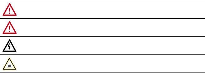
This graphic shows an example ControlLogix enhanced redundancy system, revision 19.053 or later, that uses EtherNet/IP networks.
Figure 1 -Example ControlLogix Enhanced Redundancy System, Revision 19.053 or later, Using an
EtherNet/IP Network
Workstation
EtherNet/IP
Switch
Redundant Chassis Pair
CH2 CH1 OK |
CH2 CH1 OK |
2 |
2 |
1715 Redundant I/O |
|
|
|
|
|
|
|
|
|
|
|
|
|
|
|
|
|
|
|
|
|
|
|
|
|
|
|
|
|
|
|
|
|
|
|
|
|
|
|
|
|
|
|
|
|
|
|
|
|
|
|
|
|
|
|
|
|
|
|
|
|
|
|
|
|
|
|
|
|
|
|
|
|
|
|
|
|
|
|
|
|
|
|
|
|
|
|
|
|
|
|
|
|
|
|
|
|
|
|
|
|
|
|
|
|
|
|
|
|
|
|
|
|
|
|
|
|
|
|
|
|
|
|
|
|
|
|
|
|
|
|
|
|
|
|
|
|
|
|
|
|
|
|
|
|
|
|
|
|
|
|
|
|
|
|
|
|
|
|
|
|
|
|
|
|
|
|
|
|
|
|
|
|
|
|
|
|
|
|
|
|
|
|
|
|
|
|
|
|
|
|
|
|
|
|
|
|
|
|
|
|
|
|
|
|
|
|
|
|
|
|
|
|
|
|
|
|
|
|
|
|
|
|
|
|
|
|
|
|
|
|
|
|
|
|
|
|
|
|
|
|
|
|
|
|
|
|
|
|
|
|
|
|
|
|
|
|
|
|
|
|
|
|
|
|
|
|
|
|
|
|
|
|
|
|
|
|
|
|
|
|
|
|
|
|
|
|
|
|
|
|
|
|
|
|
|
|
|
|
|
|
|
|
|
|
|
|
|
|
|
|
|
|
|
|
|
|
|
|
|
|
|
|
|
|
|
|
|
|
|
|
|
|
|
|
|
|
|
|
|
|
|
|
|
|
|
|
|
|
|
|
|
|
|
|
|
|
|
|
|
|
|
|
|
|
|
|
|
|
|
|
|
|
|
|
|
|
|
|
|
|
|
|
|
|
|
|
|
|
|
|
|
|
|
|
|
|
|
|
|
|
|
|
|
|
|
|
|
|
|
|
|
|
|
|
|
|
|
|
|
|
|
|
|
|
|
|
|
|
|
|
|
|
|
|
|
|
|
|
|
|
|
|
|
|
|
|
|
|
|
|
|
|
|
|
|
|
|
|
|
|
|
|
|
|
|
|
|
|
|
|
|
|
|
|
|
|
|
|
|
|
|
|
|
|
|
|
|
|
|
|
|
|
|
|
|
|
|
|
|
|
|
|
|
|
|
|
|
|
|
|
|
|
|
|
|
|
|
|
|
|
|
|
|
|
|
|
|
|
|
|
|
|
|
|
|
|
|
|
|
|
|
|
|
|
|
|
|
|
|
|
|
|
|
|
|
|
|
|
|
|
|
|
|
|
|
|
|
|
|
|
|
|
|
|
|
|
|
|
|
|
|
|
|
|
|
|
|
|
|
|
|
|
|
|
|
|
|
|
|
|
|
|
|
|
|
|
|
|
|
|
|
|
|
|
|
|
|
|
|
|
|
|
|
|
|
|
|
|
|
|
|
|
|
|
|
|
|
|
|
|
|
|
|
|
|
|
|
|
|
|
|
|
|
|
|
|
|
|
|
|
|
|
|
|
|
|
|
|
|
|
|
|
|
|
|
|
|
|
|
|
|
|
|
|
|
|
|
|
|
|
|
|
|
|
|
|
|
|
|
|
|
|
|
|
|
|
|
|
|
|
|
|
|
|
|
|
|
|
|
|
|
|
|
|
|
|
|
|
|
|
|
|
|
|
|
|
|
|
|
|
|
|
|
|
|
|
|
|
|
|
|
|
|
|
|
|
|
|
|
|
|
|
|
|
|
|
|
|
|
|
|
|
|
|
|
|
|
|
|
|
|
|
|
|
|
|
|
|
|
|
|
|
|
|
|
|
|
|
|
|
|
|
|
|
|
|
|
|
|
|
|
|
|
|
|
|
|
|
|
|
|
|
|
|
|
|
|
|
|
|
|
|
|
|
|
|
|
|
|
|
|
|
|
|
|
|
|
|
|
|
|
|
|
|
|
|
|
|
|
|
|
|
|
|
|
|
|
|
|
|
|
|
|
|
|
|
|
|
|
|
|
|
|
|
|
|
|
|
|
|
|
1756 ControlLogix I/O |
|
|
|
|
1734 POINT I/O™ |
PowerFlex® Drive Connected via |
||||||||||||||||||||||||||||||||
|
|
|
|
|
|
|
|
|
|
|
|
|
|
|||||||||||||||||||||||||||||||||||
|
|
|
|
|
|
|
|
|
|
|
|
|
|
|
|
|
|
|
|
|
|
|
|
|
|
|
|
|
|
|
|
|
|
|
|
|
|
|
1783-ETAP |
|||||||||
26 |
Rockwell Automation Publication 1756-UM535D-EN-P - November 2012 |
Design an Enhanced Redundancy System |
Chapter 2 |
|
|
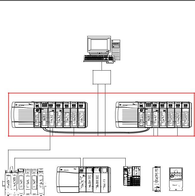
This graphic shows an example ControlLogix enhanced redundancy system, revision 19.053 or later, that uses ControlNet networks.
Figure 2 - Example ControlLogix Enhanced Redundancy System, Revision 19.053 or later, Using a
ControlNet Network
Workstation
EtherNet/IP
Switch
Redundant Chassis Pair
CH2 CH1 OK |
CH2 CH1 OK |
2 |
|
|
|
|
|
|
|
|
|
|
|
|
|
|
|
|
|
|
|
|
|
|
|
|
|
|
|
|
|
|
|
|
|
|
|
|
|
|
|
|
|
|
|
|
|
|
|
|
|
|
|
|
|
|
|
|
|
|
|
|
|
|
|
|
|
|
1756 ControlLogix I/O |
|
|
|
|
1734 POINT I/O |
PowerFlex 700S drive connected via |
|||||||||||||||||||||||
|
|
|
|
|
|
|
|
|
|
|
|
|
|
|
|
|
|
|
|
|
|
|
|
|
1788-CNCR card |
||||||
|
|
|
|
|
|
|
|
|
|
|
|
|
|
|
|
|
|
|
|
|
|
|
|
|
|
|
|
|
|
|
|
|
|
|
|
|
|
|
|
|
|
|
|
|
|
|
|
|
|
|
|
|
|
|
|
|
|
|
|
|
|
|
|
|
|
|
|
|
|
|
|
|
|
|
|
|
|
|
|
|
|
|
|
|
|
|
|
|
|
|
|
|
|
|
|
|
|
|
|
|
|
|
|
|
|
|
|
|
|
|
|
|
|
|
|
|
|
|
|
|
|
|
|
|
|
|
|
|
|
|
|
|
|
|
|
|
|
|
|
|
|
|
|
|
|
|
|
|
|
|
|
|
|
|
|
|
|
|
|
|
|
|
|
|
|
|
|
|
|
|
|
|
|
|
|
|
|
|
|
|
|
|
|
|
|
|
|
|
|
|
|
|
|
|
|
|
|
|
|
|
|
|
|
|
|
|
|
|
|
|
|
|
|
|
|
|
|
|
|
|
|
|
|
|
|
|
|
|
|
|
|
|
|
|
|
|
|
|
|
|
|
|
|
|
|
|
|
|
|
|
|
|
|
|
|
|
|
|
|
|
|
|
|
|
|
|
|
|
|
|
|
|
|
|
|
|
|
|
|
|
|
|
|
|
|
|
|
|
|
|
|
|
|
|
|
|
|
|
|
|
|
|
|
|
|
|
|
|
|
|
|
|
|
|
|
|
|
|
|
|
|
|
|
|
|
|
|
|
|
|
|
|
|
|
|
|
|
|
|
|
|
|
|
|
|
|
|
|
|
|
|
|
|
|
|
|
|
|
|
|
|
|
|
|
|
|
|
|
|
|
|
|
|
|
|
|
|
|
|
|
|
|
|
|
|
|
|
|
|
|
|
|
|
|
|
|
|
|
|
|
|
|
|
|
|
|
|
|
|
|
|
|
|
|
|
|
|
|
|
|
|
|
|
|
|
|
|
|
|
|
|
|
|
|
|
|
|
|
|
|
|
|
|
|
|
|
|
|
|
|
|
|
|
|
|
|
|
|
|
|
|
|
|
|
|
|
|
|
|
|
|
|
|
|
|
|
|
|
|
|
|
|
|
|
|
|
|
|
|
|
|
|
|
|
|
|
|
|
|
|
|
|
|
|
|
|
|
|
|
|
|
Rockwell Automation Publication 1756-UM535D-EN-P - November 2012 |
27 |

Chapter 2 Design an Enhanced Redundancy System
Redundant Chassis
You can use any ControlLogix or ControlLogix-XT chassis in a redundant chassis pair as long as the two chassis used are the same size. For example, if the primary chassis in your redundant chassis pair uses a 1756-A4 chassis, the secondary chassis must use a 1756-A4 chassis.
You can use the 1756-A4LXT chassis with the enhanced redundancy system, revision 19.052 or later. For a list of the ControlLogix chassis available for use in an enhanced redundancy system, see Table 4 on page 24.
|
TIP |
When using 1756-L7x controllers in your system, you must use revision 19.053 |
|
||
|
|
or later. |
Redundant Chassis Configuration Requirements
These configuration parameters must match for the components in a redundant chassis pair during normal system operation:
•Module type
•Chassis size
•Slot placement
•Firmware revision
•Series level. See page 32.
Figure 3 - Example of Redundant Chassis Pair
0 |
1 |
2 |
3 |
0 |
1 |
2 |
3 |
CH2 CH1 OK |
CH2 CH1 OK |
28 |
Rockwell Automation Publication 1756-UM535D-EN-P - November 2012 |

Design an Enhanced Redundancy System |
Chapter 2 |
|
|
Controllers in Redundant Chassis
Remember these points when placing controllers in the redundant chassis pair:
•Controllers are typically included, but not required, in enhanced redundancy systems.
•The differences between controller types are described in this table.
Table 5 - Controller Features
Feature |
1756-L7x Controllers |
1756-L6x Controllers |
|
|
|
Clock support and backup used for |
Energy Storage Module (ESM) |
Battery |
memory retention at powerdown |
|
|
|
|
|
Communication ports (built-in) |
USB |
Serial |
|
|
|
Connections, controller |
500 |
250 |
|
|
|
Logix CPU (processor) |
Dual-core |
Single-core |
|
|
|
Memory, nonvolatile |
Secure Digital (SD) card |
CompactFlash card |
|
|
|
Status display and status indicators |
Scrolling status display and four |
6 status indicators |
|
status indicators |
|
|
|
|
Unconnected buffer defaults |
20 (40, max) |
10 (40, max) |
|
|
|
•You can place up to two controllers in the same chassis. When you use two controllers in the same chassis, they must be of the same product family.
For example, you cannot place a1756-L6x controller and a 1756-L7x controller in the same chassis.
IMPORTANT When using a ControlLogix enhanced redundancy system, revision 16.081 or earlier, you cannot use two 1756-L64 controllers in the same
chassis. You can, however, use a 1756-L64 controller in the same chassis as a 1756-L61, 1756-L62, or 1756-L63 controller.
•You can use different catalog numbers from the same product family in the same chassis. For example, you can use two 1756-L6x controllers in a chassis.
•Each controller must have enough data memory to store twice the amount of tag data associated with a redundant controller project.
Rockwell Automation Publication 1756-UM535D-EN-P - November 2012 |
29 |

Chapter 2 Design an Enhanced Redundancy System
•Each controller must have enough I/O memory to store twice the amount of I/O memory used. To check the I/O memory used and available, access the Memory tab of the Controller Properties dialog box in RSLogix 5000 software.
For more information about data and I/O memory, see Knowledgebase Answer ID 28972.
•When you use the redundancy system update (RSU) feature to update an enhanced redundancy system while the system continues operation, the updated secondary controllers must provide the same or greater memory than the primary controllers.
A secondary controller provides greater memory than the primary controller if it is a higher catalog number, for example, a 1756-L63 primary controller and a 1756-L65 secondary controller.
This table describes the secondary controllers to which you can upgrade, based on the primary controller used, when using RSU.
Table 6 - Controller Compatibility
Primary Controller |
Compatible Secondary Controller |
|
|
1756-L61 |
1756-L61, 1756-L62, 1756-L63, 1756-L64, 1756-L65 |
|
|
1756-L62 |
1756-L62, 1756-L63, 1756-L64, 1756-L65 |
|
|
1756-L63 |
1756-L63, 1756-L64, 1756-L65 |
|
|
1756-L64 |
1756-L64, 1756-L65 |
|
|
1756-L65 |
1756-L65 |
|
|
1756-L71 |
1756-L71, 1756-L72, 1756-L73, 1756-L74, 1756-L75 |
|
|
1756-L72 |
1756-L72, 1756-L73, 1756-L74, 1756-L75 |
|
|
1756-L73 |
1756-L73, 1756-L74, 1756-L75 |
|
|
1756-L74 |
1756-L74, 1756-L75 |
|
|
1756-L75 |
1756-L75 |
|
|
Differences in controller types between chassis can exist only during the system upgrade process. When you complete the system upgrade, the controllers in the redundant chassis pair must match for the system to synchronize.
For more information on using RSU, see Appendix C, Upgrade from a Standard Redundancy System or to Another Enhanced Redundancy System on page 239.
•In an enhanced redundancy system, revision 19.052 or later, the 1756-L65 controller’s performance differs from that of the 1756-L64 controller. Some controller operations can take slightly longer for the 1756-L65 controller to complete.
For example, in some applications the 1756-L65 controller can experience longer scan times than the 1756-L64 controller.
30 |
Rockwell Automation Publication 1756-UM535D-EN-P - November 2012 |
Loading...