


 Loading...
User Manual
Dynamix 2500 Data Collector
Catalog Numbers 1441-DYN25, 1441-DYN25-Z

Important User Information
Solid-state equipment has operational characteristics differing from those of electromechanical equipment. Safety Guidelines for the Application, Installation and Maintenance of Solid State Controls (publication SGI-1.1 available from your local Rockwell Automation sales office or online at http://www.rockwellautomation.com/literature/) describes some important differences between solid-state equipment and hard-wired electromechanical devices. Because of this difference, and also because of the wide variety of uses for solid-state equipment, all persons responsible for applying this equipment must satisfy themselves that each intended application of this equipment is acceptable.
In no event will Rockwell Automation, Inc. be responsible or liable for indirect or consequential damages resulting from the use or application of this equipment.
The examples and diagrams in this manual are included solely for illustrative purposes. Because of the many variables and requirements associated with any particular installation, Rockwell Automation, Inc. cannot assume responsibility or liability for actual use based on the examples and diagrams.
No patent liability is assumed by Rockwell Automation, Inc. with respect to use of information, circuits, equipment, or software described in this manual.
Reproduction of the contents of this manual, in whole or in part, without written permission of Rockwell Automation, Inc., is prohibited.
Throughout this manual, when necessary, we use notes to make you aware of safety considerations.
WARNING: Identifies information about practices or circumstances that can cause an explosion in a hazardous environment, which may lead to personal injury or death, property damage, or economic loss.
ATTENTION: Identifies information about practices or circumstances that can lead to personal injury or death, property damage, or economic loss. Attentions help you identify a hazard, avoid a hazard, and recognize the consequence
SHOCK HAZARD: Labels may be on or inside the equipment, for example, a drive or motor, to alert people that dangerous voltage may be present.
BURN HAZARD: Labels may be on or inside the equipment, for example, a drive or motor, to alert people that surfaces may reach dangerous temperatures.
IMPORTANT Identifies information that is critical for successful application and understanding of the product.
Allen-Bradley, Rockwell Software, Rockwell Automation, Dynamix, Enpac, Emonitor, Datapac, and TechConnect are trademarks of Rockwell Automation, Inc.
Trademarks not belonging to Rockwell Automation are property of their respective companies.

Summary of Changes
New and Updated
Information
This manual contains new and updated information. Changes throughout this revision are marked by change bars, as shown to the right of this paragraph.
This table contains the changes made to this revision.
Topic |
Page |
|
|
Calibration |
27 |
|
|
Updating the Operating System |
34 |
|
|
Rockwell Automation Publication 1441-UM001B-EN-P - September 2012 |
3 |

Summary of Changes
Notes:
4 |
Rockwell Automation Publication 1441-UM001B-EN-P - September 2012 |

Table of Contents
Preface
The Dynamix 2500 Data
Collector
Optional Extension Modules. . . . . . . . . . . . . . . . . . . . . . . . . . . . . . . . . . . . . . . . 9
Dynamix 2500 Data Collector and the Emonitor Software . . . . . . . . . . 10
Software Compatibilities . . . . . . . . . . . . . . . . . . . . . . . . . . . . . . . . . . . . . . . . . 10
USB Driver and Communication Software . . . . . . . . . . . . . . . . . . . . . 10
Operating System . . . . . . . . . . . . . . . . . . . . . . . . . . . . . . . . . . . . . . . . . . . . 10
Document Conventions . . . . . . . . . . . . . . . . . . . . . . . . . . . . . . . . . . . . . . . . . . 10
Using Online Help . . . . . . . . . . . . . . . . . . . . . . . . . . . . . . . . . . . . . . . . . . . . . . . 11
Help Screen. . . . . . . . . . . . . . . . . . . . . . . . . . . . . . . . . . . . . . . . . . . . . . . . . . 11
Additional Resources . . . . . . . . . . . . . . . . . . . . . . . . . . . . . . . . . . . . . . . . . . . . . 12
Chapter 1
Safety Information . . . . . . . . . . . . . . . . . . . . . . . . . . . . . . . . . . . . . . . . . . . . . . . 15 Optical Ports. . . . . . . . . . . . . . . . . . . . . . . . . . . . . . . . . . . . . . . . . . . . . . . . . 15
Laser Radiation Ports . . . . . . . . . . . . . . . . . . . . . . . . . . . . . . . . . . . . . . . . . 15
Dynamix 2500 Data Collector Kit Parts List . . . . . . . . . . . . . . . . . . . . . . . 15 Dynamix 2500 Data Collector Optional Parts List . . . . . . . . . . . . . . . . . . 16
Parts of the Dynamix 2500 Data Collector . . . . . . . . . . . . . . . . . . . . . . . . . 17
External Connections. . . . . . . . . . . . . . . . . . . . . . . . . . . . . . . . . . . . . . . . . 19 Connector A and Connector B Inputs . . . . . . . . . . . . . . . . . . . . . . . . . 19
POWER /USB/TRIGGER . . . . . . . . . . . . . . . . . . . . . . . . . . . . . . . . . . . 20
Using the Headphones. . . . . . . . . . . . . . . . . . . . . . . . . . . . . . . . . . . . . . . . 20 Connecting to the External Power Adapter . . . . . . . . . . . . . . . . . . . . . 21
Status Indicators . . . . . . . . . . . . . . . . . . . . . . . . . . . . . . . . . . . . . . . . . . . . . 22
Strap Attachment . . . . . . . . . . . . . . . . . . . . . . . . . . . . . . . . . . . . . . . . . . . . 23 Battery Pack . . . . . . . . . . . . . . . . . . . . . . . . . . . . . . . . . . . . . . . . . . . . . . . . . 23
Check the Battery Level. . . . . . . . . . . . . . . . . . . . . . . . . . . . . . . . . . . . . . . 23
Insert and Remove the Battery Pack. . . . . . . . . . . . . . . . . . . . . . . . . . . . 26 Battery Maintenance. . . . . . . . . . . . . . . . . . . . . . . . . . . . . . . . . . . . . . . . . . 27
Calibration . . . . . . . . . . . . . . . . . . . . . . . . . . . . . . . . . . . . . . . . . . . . . . . . . . 27
Configuring the Dynamic 2500
Data Collector
Chapter 2
Apply Power to the Data Collector . . . . . . . . . . . . . . . . . . . . . . . . . . . . . . . . 29 Installing the USB Drivers for the Data Collector. . . . . . . . . . . . . . . . . . . 30
Install ActiveSync or Mobile Device Center Software. . . . . . . . . . . . 30
Install USB Drivers . . . . . . . . . . . . . . . . . . . . . . . . . . . . . . . . . . . . . . . . . . . 31 Updating the Operating System . . . . . . . . . . . . . . . . . . . . . . . . . . . . . . . . . . . 34
Install the Dynamix 2500 OS Loader Application . . . . . . . . . . . . . . . 35
Install the Dynamix 2500 Data Collector Firmware . . . . . . . . . . . . . 37 Restarting the Data Collector . . . . . . . . . . . . . . . . . . . . . . . . . . . . . . . . . . . . . 42
Perform Soft Restart . . . . . . . . . . . . . . . . . . . . . . . . . . . . . . . . . . . . . . . . . . 42
Perform Hard Restart. . . . . . . . . . . . . . . . . . . . . . . . . . . . . . . . . . . . . . . . . 42
The Data Collector’s Engineer Mode. . . . . . . . . . . . . . . . . . . . . . . . . . . 43
Dynamix 2500 Data Collector Main Menu. . . . . . . . . . . . . . . . . . . . . . . . . 45
Main Menu . . . . . . . . . . . . . . . . . . . . . . . . . . . . . . . . . . . . . . . . . . . . . . . . . . 45 Display the Operating System Version Number . . . . . . . . . . . . . . . . . 46
Rockwell Automation Publication 1441-UM001B-EN-P - September 2012 |
5 |

Table of Contents |
|
|
|
Change the Display Backlight. . . . . . . . . . . . . . . . . . . . . . . . . . . . . . . . . |
. 47 |
|
Dynamix 2500 Data Collector Setup Screen . . . . . . . . . . . . . . . . . . . . . . . . |
48 |
|
Set the Date, Time and Date Format . . . . . . . . . . . . . . . . . . . . . . . . . . . |
50 |
|
Dynamix 2500 Data Collector Data Collection Screen . . . . . . . . . . . . . . |
51 |
|
View Settings for Current Measurement Definition . . . . . . . . . . . . . |
54 |
|
Setting Up the Dynamix 2500 Data Collector . . . . . . . . . . . . . . . . . . . . . . |
55 |
|
Configure the Data Collector . . . . . . . . . . . . . . . . . . . . . . . . . . . . . . . . . . |
55 |
|
Configure the Data Collection Options . . . . . . . . . . . . . . . . . . . . . . . . |
57 |
|
Using Memory Cards . . . . . . . . . . . . . . . . . . . . . . . . . . . . . . . . . . . . . . . . . . . . . |
64 |
|
Insert and Remove a Storage Card. . . . . . . . . . . . . . . . . . . . . . . . . . . . . . |
64 |
|
Chapter 3 |
|
Setting Up Measurements |
Measurement Definition Options. . . . . . . . . . . . . . . . . . . . . . . . . . . . . . . . . . |
66 |
|
Measurement Types. . . . . . . . . . . . . . . . . . . . . . . . . . . . . . . . . . . . . . . . . . . |
67 |
|
Measurement Filters . . . . . . . . . . . . . . . . . . . . . . . . . . . . . . . . . . . . . . . . . . |
67 |
|
Measurement Units . . . . . . . . . . . . . . . . . . . . . . . . . . . . . . . . . . . . . . . . . . . |
74 |
|
Setting Up Collection Specifications . . . . . . . . . . . . . . . . . . . . . . . . . . . . . . . |
75 |
|
Edit the Measurement Definitions . . . . . . . . . . . . . . . . . . . . . . . . . . . . . |
75 |
|
Measurement Input Types. . . . . . . . . . . . . . . . . . . . . . . . . . . . . . . . . . . . . |
76 |
|
Measurement Window Types. . . . . . . . . . . . . . . . . . . . . . . . . . . . . . . . . . |
77 |
|
Measurement Signal Detection Types . . . . . . . . . . . . . . . . . . . . . . . . . . |
77 |
|
Measurement Maximum Frequencies. . . . . . . . . . . . . . . . . . . . . . . . . . . |
78 |
|
Measurement Resolution . . . . . . . . . . . . . . . . . . . . . . . . . . . . . . . . . . . . . . |
79 |
|
Number and Type of Averages . . . . . . . . . . . . . . . . . . . . . . . . . . . . . . . . . |
80 |
|
Order Normalization for Orders Track Spectrum . . . . . . . . . . . . . . . |
81 |
|
Using Frequency Items for the Diagnostic Frequency Cursor . . . . . |
82 |
|
Setting Up Speed References. . . . . . . . . . . . . . . . . . . . . . . . . . . . . . . . . . . |
83 |
|
Unsupported Measurement Selections. . . . . . . . . . . . . . . . . . . . . . . . . . |
85 |
|
Setting Up Measurement Definitions . . . . . . . . . . . . . . . . . . . . . . . . . . . . . . |
86 |
|
Magnitude Measurement Definitions. . . . . . . . . . . . . . . . . . . . . . . . . . . |
86 |
|
Magnitude and Phase Measurements at Orders . . . . . . . . . . . . . . . . . . |
89 |
|
Numeric (Process) Measurement Definitions . . . . . . . . . . . . . . . . . . . |
92 |
|
Spectrum Measurement Definitions . . . . . . . . . . . . . . . . . . . . . . . . . . . . |
95 |
|
Time Waveform Measurement Definitions . . . . . . . . . . . . . . . . . . . . . |
98 |
|
Voltage Measurement Definitions. . . . . . . . . . . . . . . . . . . . . . . . . . . . . |
100 |
|
Combine Measurement Definitions for a Location . . . . . . . . . . . . . |
101 |
|
Set Up Tri-axial Measurements . . . . . . . . . . . . . . . . . . . . . . . . . . . . . . . |
102 |
|
Setting Up Alarms, Lists, and Inspection Codes . . . . . . . . . . . . . . . . . . . . |
104 |
|
Alarms and the Data Collector. . . . . . . . . . . . . . . . . . . . . . . . . . . . . . . . |
104 |
|
Lists and the Data Collector . . . . . . . . . . . . . . . . . . . . . . . . . . . . . . . . . . |
105 |
|
Inspection Codes and the Data Collector . . . . . . . . . . . . . . . . . . . . . . |
105 |
|
Chapter 4 |
|
Loading and Unloading |
Set Up Communication. . . . . . . . . . . . . . . . . . . . . . . . . . . . . . . . . . . . . . . . . . |
107 |
|
Use the USB Connection. . . . . . . . . . . . . . . . . . . . . . . . . . . . . . . . . . . . . |
107 |
|
Install ActiveSync Software . . . . . . . . . . . . . . . . . . . . . . . . . . . . . . . . . . . |
108 |
6 |
Rockwell Automation Publication 1441-UM001B-EN-P - September 2012 |

Table of Contents
Create the Connection from the
Data Collector to a Computer . . . . . . . . . . . . . . . . . . . . . . . . . . . . . . 108
Set Up the Current Data Collector in the Emonitor software . . . 110 Loading Lists to the Data Collector . . . . . . . . . . . . . . . . . . . . . . . . . . . . . . . 113
Prepare the Data Collector before Loading . . . . . . . . . . . . . . . . . . . . 113
Initialize the Data Collector before Loading . . . . . . . . . . . . . . . . . . . 114 Loading Inspection Codes. . . . . . . . . . . . . . . . . . . . . . . . . . . . . . . . . . . . 116
Load Frequency Labels. . . . . . . . . . . . . . . . . . . . . . . . . . . . . . . . . . . . . . . 117
Override the Collect On Alarm Setting. . . . . . . . . . . . . . . . . . . . . . . . 117 Select the Lists . . . . . . . . . . . . . . . . . . . . . . . . . . . . . . . . . . . . . . . . . . . . . . 118
Load Selected Lists to the Data Collector . . . . . . . . . . . . . . . . . . . . . . 119
Display the Data Collector Driver Version Number . . . . . . . . . . . . 120 Unloading Lists from the Data Collector. . . . . . . . . . . . . . . . . . . . . . . . . . 121
Unload Lists in the Emonitor Software. . . . . . . . . . . . . . . . . . . . . . . . 122 Unload Multiple Measurements Points
in the Emonitor Software. . . . . . . . . . . . . . . . . . . . . . . . . . . . . . . . . . . 122 Unload Unscheduled (Offroute) Data from the
Dynamix 2500 Data Collector . . . . . . . . . . . . . . . . . . . . . . . . . . . . . . 123 Unload Measurements using Smart Unscheduled Mode . . . . . . . . 125 Automatically Print Reports after Unloading . . . . . . . . . . . . . . . . . . 126 Quickload Files. . . . . . . . . . . . . . . . . . . . . . . . . . . . . . . . . . . . . . . . . . . . . . 127 Load a list to the Storage Card . . . . . . . . . . . . . . . . . . . . . . . . . . . . . . . . 128
Chapter 5 |
|
Collecting and Reviewing Data Preparing for Data Collection . . . . . . . . . . . . . . . . . . . . . . . . . . . . . . . . . . . . |
129 |
Connect a Transducer to the Data Collector. . . . . . . . . . . . . . . . . . . |
130 |
Select the Data Collection Options . . . . . . . . . . . . . . . . . . . . . . . . . . . |
130 |
Collecting Route Data. . . . . . . . . . . . . . . . . . . . . . . . . . . . . . . . . . . . . . . . . . . |
131 |
Select a Route . . . . . . . . . . . . . . . . . . . . . . . . . . . . . . . . . . . . . . . . . . . . . . . |
131 |
Move through a List . . . . . . . . . . . . . . . . . . . . . . . . . . . . . . . . . . . . . . . . . |
133 |
Start Data Collection . . . . . . . . . . . . . . . . . . . . . . . . . . . . . . . . . . . . . . . . |
135 |
Select Inspection Codes . . . . . . . . . . . . . . . . . . . . . . . . . . . . . . . . . . . . . . |
137 |
Manually Enter a Numeric Measurement. . . . . . . . . . . . . . . . . . . . . . |
138 |
Collect a Process DC Voltage Measurement . . . . . . . . . . . . . . . . . . . |
139 |
Collect a Magnitude Measurement. . . . . . . . . . . . . . . . . . . . . . . . . . . . |
141 |
Collect a Spectrum Measurement . . . . . . . . . . . . . . . . . . . . . . . . . . . . . |
142 |
Collect a Time Waveform Measurement . . . . . . . . . . . . . . . . . . . . . . |
145 |
Collect Magnitude and Phase Measurements at Orders . . . . . . . . . |
146 |
Collect Multiple Measurements for a Point . . . . . . . . . . . . . . . . . . . . |
148 |
Collecting Offroute Data . . . . . . . . . . . . . . . . . . . . . . . . . . . . . . . . . . . . . . . . |
149 |
Methods for Collecting Offroute Data . . . . . . . . . . . . . . . . . . . . . . . . |
149 |
Collect Offroute Data using a Pre-defined Measurement. . . . . . . . |
150 |
Create and Collect a User-defined Point. . . . . . . . . . . . . . . . . . . . . . . |
152 |
Storing Unscheduled Data . . . . . . . . . . . . . . . . . . . . . . . . . . . . . . . . . . . . . . . |
159 |
Changing Display View. . . . . . . . . . . . . . . . . . . . . . . . . . . . . . . . . . . . . . . . . . |
161 |
Reviewing Data . . . . . . . . . . . . . . . . . . . . . . . . . . . . . . . . . . . . . . . . . . . . . . . . . |
161 |
Rockwell Automation Publication 1441-UM001B-EN-P - September 2012 |
7 |

Table of Contents
Multi-channel Measurements
Installing Optional Extension
Modules
Index
Review Route Data . . . . . . . . . . . . . . . . . . . . . . . . . . . . . . . . . . . . . . . . . . 162
Review Offroute Data . . . . . . . . . . . . . . . . . . . . . . . . . . . . . . . . . . . . . . . . 162
Review Data. . . . . . . . . . . . . . . . . . . . . . . . . . . . . . . . . . . . . . . . . . . . . . . . . 164 Use Diagnostic Frequency Cursors with a Spectrum . . . . . . . . . . . . 166
Review Waterfall Spectra Data . . . . . . . . . . . . . . . . . . . . . . . . . . . . . . . . 167
Delete a Measurement. . . . . . . . . . . . . . . . . . . . . . . . . . . . . . . . . . . . . . . . 168 Capturing Screens . . . . . . . . . . . . . . . . . . . . . . . . . . . . . . . . . . . . . . . . . . . . . . . 168
Print Reports and Plots by Using the Emonitor Software. . . . . . . . 168
Chapter 6
Two Channel Measurements . . . . . . . . . . . . . . . . . . . . . . . . . . . . . . . . . . . . . 169
Predictive Maintenance Program. . . . . . . . . . . . . . . . . . . . . . . . . . . . . . 169
Orbit Measurements. . . . . . . . . . . . . . . . . . . . . . . . . . . . . . . . . . . . . . . . . . . . . 170
Understanding an Orbit Plot . . . . . . . . . . . . . . . . . . . . . . . . . . . . . . . . . 170
Set Up Orbit Measurements Definitions
in the Emonitor Software . . . . . . . . . . . . . . . . . . . . . . . . . . . . . . . . . . . 173
Set Up Offroute Orbit Measurements . . . . . . . . . . . . . . . . . . . . . . . . . 176
Collect Orbit Measurements. . . . . . . . . . . . . . . . . . . . . . . . . . . . . . . . . . 178
Review Orbit Data Screen . . . . . . . . . . . . . . . . . . . . . . . . . . . . . . . . . . . . 182
Cross Channel Phase Measurements . . . . . . . . . . . . . . . . . . . . . . . . . . . . . . 182
Phase Tables. . . . . . . . . . . . . . . . . . . . . . . . . . . . . . . . . . . . . . . . . . . . . . . . . 183
Multi-channel Cursor, Display Expand, and
Full Scale Adjustments . . . . . . . . . . . . . . . . . . . . . . . . . . . . . . . . . . . . . 183
Set Up Cross Channel Phase Measurement Definitions in the
Emonitor Software . . . . . . . . . . . . . . . . . . . . . . . . . . . . . . . . . . . . . . . . . 184
Set Up an Offroute Cross Channel Phase Measurement. . . . . . . . . 185
Collect a Cross Channel Phase Measurement . . . . . . . . . . . . . . . . . . 188
Review Cross Channel Phase Data . . . . . . . . . . . . . . . . . . . . . . . . . . . . 190
Dual Channel Measurements. . . . . . . . . . . . . . . . . . . . . . . . . . . . . . . . . . . . . 192
Set Up Dual Channel Measurement Definitions
in the Emonitor Software . . . . . . . . . . . . . . . . . . . . . . . . . . . . . . . . . . . 192
Collect an Offroute Dual Channel Measurement. . . . . . . . . . . . . . . 193
Magnitude and Phase Offroute Measurement. . . . . . . . . . . . . . . . . . . . . . 196
Multi-channel Measurements. . . . . . . . . . . . . . . . . . . . . . . . . . . . . . . . . . . . . 197
Collect a 4-channel Measurement . . . . . . . . . . . . . . . . . . . . . . . . . . . . . 197
Collect Multi-channel Measurements . . . . . . . . . . . . . . . . . . . . . . . . . 198
Collect a Tri-axial Measurement . . . . . . . . . . . . . . . . . . . . . . . . . . . . . . 202
Chapter 7
Install Optional Extension Modules. . . . . . . . . . . . . . . . . . . . . . . . . . . . . . . 205
Uninstall an Extension Module . . . . . . . . . . . . . . . . . . . . . . . . . . . . . . . . . . . 207
Manage Extension Modules . . . . . . . . . . . . . . . . . . . . . . . . . . . . . . . . . . . . . . 209
8 |
Rockwell Automation Publication 1441-UM001B-EN-P - September 2012 |

Preface
Optional Extension
Modules
This manual covers the Dynamix™ 2500 data collector module which is used for predictive maintenance using noise and vibration analysis.
When using the Dynamix 2500 data collector, you can do the following:
•Create lists of measurement definitions.
•Load lists from Emonitor® into the Dynamix 2500 data collector.
•Use an 80 Khz fmax, Route and Offroute.
•Collect magnitude, process, spectrum, time, and phase data.
•View selected alarms.
•Select inspection codes to store with a measurement.
•Define and collect unscheduled measurements
•Unload the data from the Dynamix 2500 data collector directly into the Emonitor database.
•View the high resolution, up to 25,600 lines on the data collector.
These are the optional extension modules for the Dynamix 2500 data collector:
•1441-DYN25-4C, 4-Channel Activation (1)
The 4-channel activation lets you take 3 and 4 channel magnitude, time waveform, spectra, and Offroute measurements.
•1441-DYN25-MBMP Bump Test
A bump test (or hammer test) determines the natural frequencies of a machine or a structure.
•1441-DYN25-MBAL Balancing
Balancing application resolves single-plane, two-plane, and static-couple balances with high precision.
•1441-DYN25-MFRF Frequency Response Function
The FRF test lets you determine the natural frequencies of a machine as well as sophisticated information about the frequency response of the structure being tested.
•1441-DYN25-MREC Time Recorder
The Time Recorder test uses a the instrument as a data recorder for realtime data acquisition and analysis.
•1441-DYN25-MRUC Run Up Coast Down
The RUCD test records and analyzes data from intermittent events and transient vibration signals from non-steady state machines.
See Additional Resources on page 12 for a listing of available publications.
(1) This is an activation license for the Dynamix 2500 data collector.
Rockwell Automation Publication 1441-UM001B-EN-P - September 2012 |
9 |

Preface
Dynamix 2500 Data
Collector and the Emonitor
Software
The terminology in the data collector and the software differ in several ways. This table illustrates the differences.
Table 1 Terminology Differences
Dynamix 2500 Terminology |
Emonitor Terminology |
|
|
Offroute |
Unscheduled measurements |
Measurements that are taken but are not |
Measurements that are not defined in the list of |
downloaded on to the instrument from Emonitor. |
measurements downloaded by Emonitor. |
These measurements can be upload to Emonitor. |
These measurements are unscheduled. |
|
|
Route |
List |
The Dynamix 2500 data collector uses the term |
The Emonitor software uses the term ‘list’ for an |
route’ to refer to a list loaded in the data |
ordered set of measurement definitions. |
collector. |
|
|
|
Software Compatibilities |
The Dynamix 2500 data collector requires the following software versions. |
USB Driver and Communication Software
•USB communication with Microsoft Windows 2000 and Windows XP is supported using Microsoft ActiveSync software version 4.5 or greater
•USB communication with Microsoft Windows 7 is supported using Microsoft Mobile Device Center
•Microsoft Windows 7 32 bit and/or Microsoft Windows 7 64 bit are supported
Operating System
Document Conventions
•Microsoft Windows 2000 (SP4) with ActiveSync software
•Microsoft Windows XP (SP3) with ActiveSync software
•Microsoft Windows 7 with Mobile Device Center software installed
These are document conventions used in this manual.
•The Dynamix 2500 data collector is referred to as a data collector and an instrument in this manual.
•The different versions of the Emonitor software are Enterprise, Factory, and Workstation. These are all are referred to as the Emonitor software in this manual.
•The Emonitor software screen captures are from version 3.4 and reference the Enpac 2500 data collector. The next version of the Emonitor software and this manual will reflect the name Dynamix 2500 data collector.
10 |
Rockwell Automation Publication 1441-UM001B-EN-P - September 2012 |
Preface
Using Online Help
The Emonitor software and the Dynamix 2500 data collector each include online help:
•Emonitor Online Help
The Emonitor online help is available from the Emonitor Help menu or by pressing F1.
•Dynamix 2500 Online Help
The Dynamix 2500 data collector online help is available from any screen where the Help function appears. Press F1 (Help) to access the online help.
On some screens that do not display the Help function, pressing Shift(0) provides access also to the Help.
Help Screen
Press F1 (Help) to access online help from any screen where the Help function is displayed on the screen.
1.Press F1 (Help) to access the online help. The Help Contents screen appears.
To highlight a topic, use the
Up or Down arrows.
2.Select the topic for which you want to view and press F1 (Goto).
3.When you are finished viewing the topic, press F1 (Contents) to return to the Help Contents screen or press F4 (Esc) to exit the online help.
Rockwell Automation Publication 1441-UM001B-EN-P - September 2012 |
11 |

Preface
Additional Resources
These documents contain additional information concerning related products from Rockwell Automation®.
Resource |
Description |
|
|
Bump Test Extension Module for the Dynamix 2500 |
Describes how determine natural (or resonant) |
Data Collector User Manual, |
frequencies of a machine or structure. |
publication 1441-UM002 |
|
|
|
Frequency Response Function Extension Module |
Describes how to determine the natural |
for the Dynamix 2500 Data Collector User Manual, |
frequencies of a machine or structure using |
publication 1441-UM003 |
modal hammer. |
|
|
Balancing Extension Module for the Dynamix 2500 |
Describes the direct method to balance your |
Data Collector User Manual, |
rotating machinery in one or two planes. |
publication 1441-UM004 |
|
|
|
Time Recorder Extension Module for the Dynamix |
Describes how to use the data collector as a |
2500 Data Collector User Manual, |
data recorder for real-time data acquisition, |
publication 1441-UM005 |
post processing, and analysis. |
|
|
Run Up Coast Down Extension Module for the |
Describes how to record and analyze data from |
Dynamix 2500 Data Collector User Manual, |
intermittent events and transient vibration |
publication 1441-UM006 |
signals from nonsteady state machines. |
|
|
Emonitor User’s Guide, publication |
Describes data management for predictive |
EMONTR-UM001 |
maintenance services. |
|
|
Dynamix 2500 Data Collector Kit Release Notes, |
Provides important information on the latest |
publication 1441-RN001 |
updates, for example, firmware, certifications, |
|
warnings, and hardware changes for the data |
|
collector. |
|
|
Dynamix 2500 Data Collector Optional Extension |
Provides important information on how to |
Modules Release Notes, publication 1441-RN002 |
install the Optional Extension Modules onto |
|
the Dynamix 2500 data collector. |
|
|
Industrial Automation Wiring and Grounding |
Provides general guidelines for installing a |
Guidelines, publication 1770-4.1 |
Rockwell Automation industrial system. |
|
|
Product Certifications website, http://www.ab.com |
Provides declarations of conformity, |
|
certificates, and other certification details. |
|
|
You can view or download publications at http://www.rockwellautomation.com/literature. To order paper copies of technical documentation, contact your local Allen-Bradley® distributor or Rockwell Automation sales representative.
12 |
Rockwell Automation Publication 1441-UM001B-EN-P - September 2012 |

Chapter 1
The Dynamix 2500 Data Collector
This chapter describes the Dynamix 2500 data collector and explains the instrument’s basic and configuration and operation.
Topic |
Page |
|
|
Safety Information |
15 |
|
|
Parts of the Dynamix 2500 Data Collector |
17 |
|
|
External Connections |
19 |
|
|
Connector A and Connector B Inputs |
19 |
|
|
Using the Headphones |
20 |
|
|
Connecting to the External Power Adapter |
21 |
|
|
Dynamix 2500 Data Collector Kit Parts List |
15 |
|
|
Status Indicators |
22 |
|
|
Battery Pack |
23 |
|
|
The Dynamix 2500 data collector is a real-time multi-channel Fast Fourier Transforms (FFT) analyzer and data collector for predictive maintenance and machinery vibration diagnostics. It is capable of measuring, processing, displaying and storing a wide range of analysis functions. It can operate as a stand alone instrument or you can download your measurements to your software application for program analysis.
The combination of the Dynamix 2500 data collector with the Emonitor software provides you with the tools for predictive maintenance using noise and vibration analysis. The data collector can be used for a variety of other applications also, such as balancing or bearing analysis.
A predictive maintenance program helps you decide when equipment needs to be serviced or replaced. Part of a complete predictive maintenance program includes vibration monitoring. The Emonitor software and the Dynamix 2500 data collector let you to perform vibration analysis by collecting data samples.
Rockwell Automation Publication 1441-UM001B-EN-P - September 2012 |
13 |

Chapter 1 The Dynamix 2500 Data Collector
With the combination of predictive maintenance software and the Dynamix 2500 data collector, you can do the following:
•Create lists of measurement definitions for data collection.
•Load lists from the Emonitor software into the Dynamix 2500 data collector.
•Collect magnitude, process, spectrum, time, and phase data.
•View selected alarms with the data.
The Dynamix 2500 data collector alerts you when a measurement exceeds an alarm.
•Define and collect unscheduled measurements.
•Select inspection codes to store with a measurement, documenting the condition of the machine.
•Unload the data from the Dynamix 2500 data collector directly into the Emonitor database, along with any inspection codes and unscheduled measurements.
In addition, the Emonitor software can optimize your data collection by combining measurement definitions at a location. For example, the software can combine magnitude and spectrum measurement definitions so that the list appears to contain only a single measurement. This lets you to collect all three measurements at one time, minimizing the time you spend collecting data.
14 |
Rockwell Automation Publication 1441-UM001B-EN-P - September 2012 |
The Dynamix 2500 Data Collector |
Chapter 1 |
|
|
Safety Information
Dynamix 2500 Data
Collector Kit Parts List
Be aware of these safety precautions.
IMPORTANT Avoid Water
The Dynamix 2500 data collector is splash and dust resistant. However, avoid direct contact with water, wet surfaces, or condensing humidity. Keep this instrument away from wet locations, for example, laundry, wet basements, swimming pools.
If the data collector subject to these conditions, adverse operation may result. Before you use it, let the instrument dry thoroughly before operating.
ATTENTION: To avoid damage or injury, place the Dynamix 2500 data collector on a solid stable surface when not in use and do not place any heavy objects on it. Use only the accessories recommended by Rockwell Automation. Keep liquids and foreign objects away from the instrument, and never operate it if any liquid or foreign object has entered it.
Optical Ports
ATTENTION: When the laser on the data collector is active, viewing the laser beam can expose your eyes beyond the maximum permissible exposure recommendations and cause harm.
Laser Radiation Ports
ATTENTION: Class 1 laser product. Laser radiation is present when the system is open and interlocks bypassed. Only trained and qualified personnel should be allowed to install, replace, or service the instrument.
This table list the parts list for the data collector kit.
Table 2 - Dynamix 2500 Data Collector Kit Parts List, 1441-DYN25-2C
Catalog No. |
Description |
|
|
1441-DYN25-Z |
Dynamix 2500 data collector |
|
|
1441-DYN25-CAP |
Dust Cap Set for Inputs |
|
|
1441-DYN25-CD |
Operating System and Documentation CD |
|
|
1441-DYN25-PS |
Global Power Supply |
|
|
1441-PEN25-BAT |
Battery |
|
|
1441-PEN25-CASE-T |
Transit Case |
|
|
1441-PEN25-COMS-US |
Communication Cable USB Power Splitter |
|
|
1441-PEN25-HS |
Hand Strap |
|
|
1441-PEN25-RBS |
Rubber Bump Sleeve |
|
|
The Dynamix 2500 data collector, catalog number, 1441-DYN25-Z-2C, is for ATEX Zone 2 and IECEx for hazardous environments. This kit contains the same parts as the Dynamix 2500 data collector,
catalog number 1441-DYN25-2C except 1441-DYN25-Z replaces 1441DYN25.
Rockwell Automation Publication 1441-UM001B-EN-P - September 2012 |
15 |

Chapter 1 The Dynamix 2500 Data Collector
Dynamix 2500 Data
Collector Optional Parts
List
This table list the optional hardware parts list for the data collector.
Table 3 - Dynamix 2500 Data Collector Optional Parts List
Cat. No. |
Description |
|
|
1441-DYN25-CBL2CH |
2 Channel Adapter Cable for Connectors A or B |
|
|
1441-DYN25-CBLHS |
Headset Adapter Cable |
|
|
1441-DYN25-CD |
Dynamix 2500 Operating System & Info CD |
|
|
1441-DYN25-M4CH |
4 Channel Activation |
|
|
1441-DYN25-MBAL |
2 Plane Balancing Extension Module |
|
|
1441-DYN25-MBMP |
Bump Test Extension Module |
|
|
1441-DYN25-MFRF |
Frequency Response Extension Module |
|
|
1441-DYN25-MREC |
Time Recorder Extension Module |
|
|
1441-DYN25-MRUC |
Run Up Coast Down Extension Module |
|
|
1441-DYN25-PS |
Global Power Supply |
|
|
1441-PEN25-BAT |
Spare Battery |
|
|
1441-PEN25-CASE-T |
Transit Case |
|
|
1441-PEN25-COMS-US |
Communication Cable USB Power Splitter |
|
|
1441-PEN25-HS |
Hand Strap |
|
|
1441-PEN25-NS |
Neck Strap |
|
|
1441-PEN25-RBS |
Rubber Bump Sleeve |
|
|
1441-PEN25-Z2-100 |
100 mV per G Zone II Accel Kit |
|
|
1441-PEN25-Z2-50 |
50 mV per G Zone II Accel Kit |
|
|
16 |
Rockwell Automation Publication 1441-UM001B-EN-P - September 2012 |
The Dynamix 2500 Data Collector |
Chapter 1 |
|
|
Parts of the Dynamix 2500
Data Collector
This section describes the basic components of the Dynamix 2500 Data Collector including key definitions, hardware connections, and status indicators.
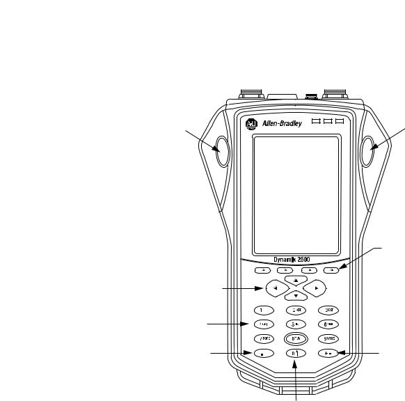
Figure 1 - The Dynamix 2500 Data Collector Keys
Enter |
Enter |
Function Keys
Arrow Keys

 On/Off
Numeric Keys
Decimal |
+/- |
0 or Shift
32142-M
Rockwell Automation Publication 1441-UM001B-EN-P - September 2012 |
17 |

Chapter 1 The Dynamix 2500 Data Collector
Table 4 - Dynamix 2500 Data Collector Key Definitions
Keys |
Definition |
|
|
Enter |
The two Enter buttons are on either side of the LCD display. In any screen, |
|
pressing one of the Enter buttons selects the highlighted option, or |
|
progresses through data collection screens. |
|
Either left/right Enter key does the following in different situations: |
|
• Same as using the Apply function key. |
|
• Starts collecting data for the current point or accepts the current |
|
measurement. |
|
• Accepts changes to parameter selections. |
|
• May be referred also as the Fire, Read, and OK key. |
|
• In many screens the Left arrow will take you back one screen as will F4 |
|
(Esc) and the Right arrow will act the same as Enter and go forward. |
|
|
Function keys |
The four function keys used are F1, F2, F3, and F4. The functions change |
|
depending on the current state of the data collector. |
|
The data collector displays the current function of the keys in the data |
|
collector screen. When no text appears above a function key, the key is |
|
inactive in the current window. |
|
Many functions provide an additional row of function keys. By pressing the |
|
shift (0) key, the data collector provides another row of function keys, still |
|
referred to as F1…F4. |
|
For example: When you go to the Setup menu, F1…F4 appear as Help, Cont. |
|
- (less screen contrast), Cont. + (more screen contrast), and Apply. After |
|
pressing the shift (0) key, the functions change to Extn Mngr (Extension |
|
Manager) and Calib (Calibration). |
|
You will notice that if you don’t hold down the shift (0) key for a longer |
|
period of time the first set of functions reappear. |
|
|
Up arrow |
• Moves to the previous field or menu selection. |
|
• Decreases the Y-axis scaling in a signature plot. |
|
|
Down arrow |
• Moves to the next field or menu selection. |
|
• Increases the Y-axis scaling in a signature plot. |
|
|
Left arrow |
• Displays the previous screen of information if there is more than one |
|
screen, for example, selecting a point in the Data Collection screen. |
|
• Closes the menu selection on the Setup and Instrument Configuration |
|
screens. |
|
• Moves the signature cursor to the left. |
|
|
Right arrow |
• Displays the next screen of information if there is more than one screen, |
|
for example, selecting a point in the Data Collection screen. |
|
• Opens the menu selection on the Setup and Instrument Configuration |
|
screens. |
|
• Moves the signature cursor to the right. |
|
|
On/Off |
Turns the instrument on and off. |
|
To turn the instrument off, press and hold the On/Off key for one second. |
|
|
Numeric |
Enter alpha/numeric values. |
|
|
Decimal (.) |
Check the status of the battery, or type a decimal point in a numeric field. |
|
See Check the Battery Level on page 23 for more information. |
|
|
+/- |
Expand or compress a signature plot on the data collector screen. |
|
|
0 |
Acts as a `shift’ key that has multiple uses depending on the current data |
|
collector operation: |
|
• In a Setup screen numeric input field, the key acts as a zero. |
|
• In all other screens, pressing and holding the key displays alternate |
|
functions for the function keys. |
|
|
18 |
Rockwell Automation Publication 1441-UM001B-EN-P - September 2012 |

The Dynamix 2500 Data Collector |
Chapter 1 |
|
|
External Connections
The external hardware connections for communication and data collection are located on the top panel of the Dynamix 2500 data collector.
Figure 2 - External Hardware Connections
A |
|
POWER/USB/ |
LASER |
B |
|
||||
|
|
|
TRIGGER |
|
|
|
|
||
1 |
6 |
|
|
2 |
|
|
1 |
6 |
|
2 |
7 |
5 |
3 |
7 |
|
2 |
7 |
5 |
|
3 |
4 |
|
4 |
1 |
6 |
|
3 |
4 |
|
|
|
|
|
5 |
|
|
|
|
|
32144-M
Connector A and Connector B Inputs
The data collector has two signal inputs (LEMO connectors), connector A and
B. Headphone access is supported on Connectors A and B.
Table 5 - Dynamix 2500 Data Collector Pin Assignments
Pin |
Connector A |
Connector B |
POWER/USB/TRIG |
|
|
|
|
1 |
Audio Output |
Audio Output |
USBV |
|
|
|
|
2 |
Channel X |
Channel Y |
USB+ |
|
|
|
|
3 |
Channel Z |
N/C |
USB- |
|
|
|
|
4 |
Strobe Out |
Strobe Out |
DIGITAL GND |
|
|
|
|
5 |
ANALOG GND |
ANALOG GND |
EXT-DC-IN |
|
|
|
|
6 |
Channel Y |
N/C |
± 25 V EXT-TRIG-IN |
|
|
|
|
7 |
Channel R |
Channel Z |
+5V DC TACHO SUPPLY |
|
|
|
|
The measurement Input signal range is ±25 V maximum. Input over voltage protection is AC ± 50 V peak, DC ± 50 V. The inputs are protected ±50 V AC or DC sustained against high-voltage transients, but trigger range over-voltage input levels must be avoided.
Voltage can be DC or AC coupled, while the third option, Accel (ICP) 24 V DC @ 2.4mA, is available for direct connection of integrated circuit piezoelectric transducers. These settings are specified in the Emonitor software.
TIP |
In some circumstances you may find a reference to channel numbers |
|
instead of X, Y, Z or R. Channel numbers can be cross referenced to |
|
X= Ch(1), Y = Ch(2), Z= Ch(3), R = Ch(4). |
See Setting Up Measurements on page 65 for more information.
Rockwell Automation Publication 1441-UM001B-EN-P - September 2012 |
19 |

Chapter 1 The Dynamix 2500 Data Collector
POWER /USB/TRIGGER
This socket connects the Dynamix 2500 data collector to either an external trigger, power adapter, or a USB interface. The external trigger enables the synchronization of the data acquisition process to external events, such as tachometer inputs for rotational synchronization for balancing applications, or for order normalization of frequency spectrum. You can use the trigger pulse also to collect running speeds of machinery. The pin assignment for the trigger is shown in Dynamix 2500 Data Collector Pin Assignments on page 19.
Using the Headphones
The Dynamix 2500 data collector lets you listen to the vibration signal as measurements are being recorded. You need to have the optional part, the headset adapter cable.
You can use either Connector A, or Connector B to listen to any data being collected. The accelerometer would be connected to the opposite connector. When collecting data, the headphone output is switched to listen to another input channel (X, Y, Z, and R) by using the shift + left and right arrows.
The headphone output always cycles through X, Y, Z, and R, but only outputs sound when set to a channel that is currently measuring data. The channels that are collecting data are controlled by which connector (A, or B) that the accelerometer is connected to.
See Dynamix 2500 Data Collector Optional Parts List on page 16.
You can control the volume using the keypad on the data collector. You can listen to any channel.
The status bar on the top of the screen indicates the monitored channel and the headphone volume. You can listen to the following:
•Connector A: Channels X, Y, Z, and R
•Connector B: Channels Y and Z
Table 6 - Headphone Controls
Keys |
Description |
|
|
6(M) |
Toggles mute on and off for current channel |
|
|
Shift, up arrow or shift, down arrow |
Adjusts the volume 0…10 |
|
|
Shift, left arrow or shift, right arrow |
Cycle through channels you are monitoring |
|
|
20 |
Rockwell Automation Publication 1441-UM001B-EN-P - September 2012 |
The Dynamix 2500 Data Collector |
Chapter 1 |
|
|
Connecting to the External Power Adapter
The external power adapter can be used to charge the internal battery and the battery pack.
WARNING: When you are powering or charging the data collector, place the power adapter in a well ventilated area. The data collector may overheat and cause a fire.
WARNING: Only the provided power supply may be used. Any other supply may cause permanent damage to the data collector.
WARNING: Connect the power supply only in a safe nonhazardous area.
1.Connect the data collector to the DC output of the power supply to the in-line socket of the USB power splitter cable.
2.Connect the Fischer plug into the POWER/USB/TRIGGER socket on top of the instrument.
3.When needed, use the USB splitter cable to connect to a computer.
The interface is configured as a Client to provide an automatic connection to a computer through the Microsoft ActiveSync software. This interface lets you to copy files and transfer data from the data collector to your computer.
See Install ActiveSync Software on page 108 for more information.
Figure 3 - The Dynamix 2500 Data Collector Connections for the
USB/Power Splitter Cable
Line red dots up to insert
USB cable |
External power |
|
adapter |
|
In-line socket |
32145-M
Rockwell Automation Publication 1441-UM001B-EN-P - September 2012 |
21 |
Chapter 1 The Dynamix 2500 Data Collector
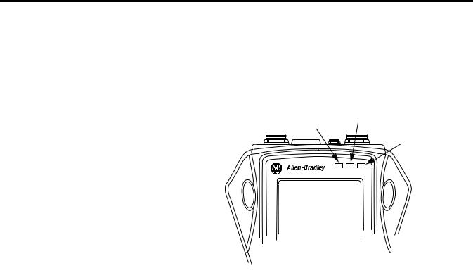
Status Indicators
The Dynamix 2500 data collector has four status indicators located in the upper-right side of the instrument nameplate.
Figure 4 - Status Indicators
Amber
Dual Status: Red and Blue
Green
|
|
|
32146-M |
Table 7 - Status Indicators |
|
|
|
|
|
|
|
Status |
Operation |
State |
Definition |
Indicator |
|
|
|
|
|
|
|
Dual State |
Charging Battery |
Flashing |
When first connected to the power adapter, the |
Status |
|
|
Dynamix 2500 Data Collector tests the condition of |
Red |
|
|
the battery pack. Within 30 seconds, the status |
|
|
indicators should go to a solid state. |
|
|
|
|
|
|
|
|
If the status indicator continues to flash, the |
|
|
|
instrument has diagnosed a fault in the battery pack |
|
|
|
and it will not charge the battery. The anomaly may |
|
|
|
be that the cell temperature is too high or there is a |
|
|
|
fault with the battery pack. |
|
|
|
|
|
|
Solid |
The battery pack is OK. The power adapter is |
|
|
|
connected to the instrument and charging. The |
|
|
|
battery pack is maintained by a trickle charge from |
|
|
|
the power adapter for as long as it remains attached |
|
|
|
to the instrument. |
|
|
|
|
|
Data Collection |
Solid |
• An alarm condition has been set. |
|
|
|
• Input signal is out of range. |
|
|
|
• ICP check has failed and there is an ICP fault |
|
|
|
condition. |
|
|
|
• The power adapter is connected to the |
|
|
|
instrument. |
|
|
|
|
Blue |
Communication |
Solid |
• Communicating to Emonitor through the USB |
|
|
|
connection. |
|
|
|
|
Amber |
Data Collection |
Solid |
Acquisition sub-system is settling. |
|
|
|
|
Green |
Data Collection |
Solid |
Input signal is stable and data is ready to be stored. |
|
|
|
|
22 |
Rockwell Automation Publication 1441-UM001B-EN-P - September 2012 |

The Dynamix 2500 Data Collector |
Chapter 1 |
|
|
Strap Attachment
The strap can be fitted to either the left or right side of the Dynamix 2500 data collector.
1.Feed the ends of the strap through the top and bottom corner pillars.
2.Loop the ends of the strap through the buckles and adjust the tightness to suit.
Battery Pack
The Dynamix 2500 data collector can be powered either from the battery pack or the external power supply. The internal back-up battery maintains the system settings is used while replacing the battery pack. This internal battery keeps the data collector on for a very short period of time.
WARNING: To make sure proper and safe Dynamix 2500 data collector operation, only use the supplied battery pack.
If you do not replace the battery pack quickly the data collector will shut down resulting in a hard restart. If this occurs, the following happens:
•Data you have not saved will be lost.
•Last system settings will be reset to defaults.
•You will not be taken back to your last the location when the restart occurs.
The most efficient way to replace the battery pack is to do one of the following:
•Connect to a power source then remove the battery.
•Save your data and turn off the data collector to remove the battery.
Check the Battery Level
You can check the level of the data collector’s battery at any time by looking at the top status bar on the screen.
Rockwell Automation Publication 1441-UM001B-EN-P - September 2012 |
23 |
Chapter 1 The Dynamix 2500 Data Collector
This table shows the typical battery life for a fully charged battery pack
Table 8 - Battery Capacity
Mode |
|
State |
Typical Battery Life |
|
|
|
|
|
|
On |
|
Performing typical data collection |
8 hours minimum |
|
|
|
|
|
|
|
|
Idle mode |
14 hours minimum |
|
|
|
|
|
|
Off |
|
Main battery & back-up battery |
14 days minimum |
|
|
|
|
|
|
|
|
Main battery removed & instrument |
2 days minimum |
|
|
|
running on back-up battery |
|
|
|
|
|
|
|
Main Battery Charge |
|
100% |
5 hours |
|
Time |
|
|
|
|
|
70% |
3 hours |
|
|
|
|
|
||
|
|
|
|
|
|
|
|
||
IMPORTANT |
If you let the main battery discharge completely, the instrument will |
|
||
|
behave as if it has experienced a hardware reset. On restart the |
|
||
|
current date, time and status information will be lost. |
|
||
|
|
|
|
|
You can check the status of the battery also in the instrument by pressing the decimal (.) key. This function is available on most screens.
The Battery status display reports the status of the internal battery and the condition of the instrument’s back-up battery. The back-up battery charges while the instrument is connected to the external DC power adapter or when the instrument is powered on using the internal battery.
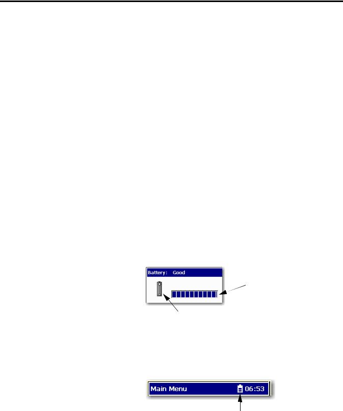
Figure 5 - Battery Status Display
 Battery pack indicator
 Indicates that the data collector is operating with the battery pack. When using a power supply, this changes to a plug and indicates that the battery pack is charging.
The battery status appears in the upper-right corner of the caption bar, as illustrated below.
Figure 6 - Battery Pack Status Indicator
Battery pack status indicator
24 |
Rockwell Automation Publication 1441-UM001B-EN-P - September 2012 |
The Dynamix 2500 Data Collector |
Chapter 1 |
|
|
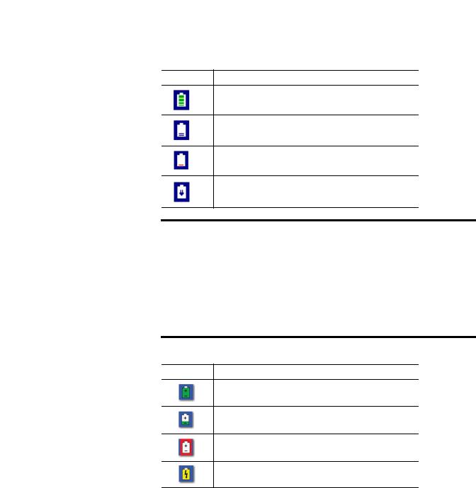
The battery status icons show the strength of the battery.
Table 9 - Battery Status Icons
Battery Icon Meaning
Battery status is good: >30% life remaining.
Battery status is low: >10% life remaining.
Battery status is very low: <10% life remaining.
Battery is charging.
IMPORTANT The Dynamix 2500 data collector automatically notifies you when the battery status is at 30% or lower. To clear the notification, press the decimal (.) key. The notification periodically appears until the battery is recharged or the power adapter is attached.
To prevent any loss of data, we do not recommend that you use USB communication when the battery status is at 10% or lower.
Table 10 - Dynamix 2500 Extension Module Battery Icon Descriptions
Battery Icon Meaning
Battery status is good: >30% life remaining.
Battery status is low: >10% life remaining.
Battery status is very low: <10% life remaining.
Battery is charging.
Rockwell Automation Publication 1441-UM001B-EN-P - September 2012 |
25 |

Chapter 1 The Dynamix 2500 Data Collector
Insert and Remove the Battery Pack
WARNING: To make sure proper and safe Dynamix 2500 data collector operation, only use the supplied battery pack.
1.On the back of the instrument, use a flat head screwdriver to unlatch the release screws.
Figure 7 - Rear View of the Dynamix 2500 Data Collector
Once battery cover is removed, slide the battery to the left and  lift out.
Reset switch
 Release screws to access battery pack.
2. Remove the battery cover.
WARNING: Only remove the battery in a nonhazardous environment:
• Avoid Battery Compartment Exposure.
• Do not open the battery compartment in a hazardous area, or in locations where contact with water or other contaminants may occur.
WARNING: To minimize the risk of serious injury or damage do the following:
•Do not expose the battery pack to temperatures in excess of 60 °C (140 °F).
•Do not disassemble, incinerate, or short-circuit the battery pack.
•Danger of explosion if battery is incorrectly replaced.
•Replace the battery only with the same or equivalent type recommended by the manufacturer.
•Dispose of used batteries according to the manufacturer’s instructions.
•Do not open battery compartment in a hazardous / explosive area.
3.Slide the battery pack to the left and lift it out.
26 |
Rockwell Automation Publication 1441-UM001B-EN-P - September 2012 |
The Dynamix 2500 Data Collector |
Chapter 1 |
|
|
Battery Maintenance
These are recommendations to extend the life of the battery pack:
•If the data collector is not in use and/or not regularly charged, it should be recharged at least every 25 days to prevent damage to the battery cells.
•If the battery pack is not installed recharge the battery pack every 12 months to prevent damage to the battery cells.
•Recalibrate the electronic state of charge meter around every 30th recharge. This prevents the state of charge from showing an incorrect battery charge percentage. To do this, fully discharge the battery pack and then fully charge it without any interruptions, ideally with the data collector off. It will take longer to charge the battery if the data collector is on while charging.
•The battery capacity is reduced at temperature extremes, high and low.
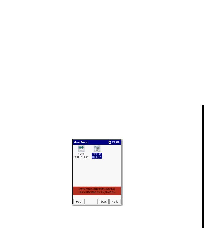
Calibration
After a 12-month period, you may notice that a calibration reminder message appears at the bottom of the Main Menu screen. This is just a reminder to get your instrument calibrated. To hide the reminder message, select Calib (F4) and the message will be hidden until the following month.
We recommend that you return the Dynamix 2500 data collector annually to
Allen-Bradley for calibration. For more information, see Rockwell Automation
Support on the back cover.
Rockwell Automation Publication 1441-UM001B-EN-P - September 2012 |
27 |

Chapter 1 The Dynamix 2500 Data Collector
Notes:
28 |
Rockwell Automation Publication 1441-UM001B-EN-P - September 2012 |

Chapter 2
Configuring the Dynamic 2500 Data Collector
Apply Power to the Data Collector
This chapter describes what you need to do to configure the data collector.
Topic |
Page |
|
|
Apply Power to the Data Collector |
29 |
|
|
Installing the USB Drivers for the Data Collector |
30 |
|
|
Updating the Operating System |
34 |
|
|
Restarting the Data Collector |
42 |
|
|
Dynamix 2500 Data Collector Main Menu |
45 |
|
|
Dynamix 2500 Data Collector Setup Screen |
48 |
|
|
Dynamix 2500 Data Collector Data Collection Screen |
51 |
|
|
Setting Up the Dynamix 2500 Data Collector |
55 |
|
|
Using Memory Cards |
64 |
|
|
After connecting the data collector to AC power or installing the battery, a single press of the On/Off key applies power to the instrument. However, to power off the instrument you need to press On/Off for a period of one second. The instrument resumes operation at the last screen you viewed when you powered off the data collector.
TIP |
The first time you turn on the Dynamix 2500 Data Collector or |
|
following a reset, the Instrument Setup screen automatically appears. |
|
See Set the Date, Time and Date Format on page 50 for more |
|
information. |
Rockwell Automation Publication 1441-UM001B-EN-P - September 2012 |
29 |

Chapter 2 Configuring the Dynamic 2500 Data Collector
Installing the USB Drivers for the Data Collector
You can communicate between the Dynamix 2500 data collector and your computer by installing specific USB driver files and communication software. If you want to load and unload routes to your data collector you must install Microsoft ActiveSync software and the USB drivers.
Install ActiveSync or Mobile Device Center Software
When using Microsoft Windows 2000 or Windows XP, use the ActiveSync software to communicate through the USB connection. You can download the ActiveSync software from
http://www.microsoft.com/downloads. Follow the instructions on the website to download and install ActiveSync software.
TIP |
We recommend that you use ActiveSync software version 4.5 or later |
|
when using the Dynamix 2500 data collector. |
When using Microsoft Windows 7, use the Mobile Device Center software. You can download the Mobile Device Center software from http://www.microsoft.com/downloads.
Follow the instructions on the website to download and install the Mobile Device Center software.
TIP |
Microsoft ActiveSync software automatically launches and asks to Set |
|
Up a Partnership. Select No and click Next. ActiveSync software then |
|
displays its Connected dialog. |
|
See Install ActiveSync or Mobile Device Center Software on page 30 for |
|
more information. |
30 |
Rockwell Automation Publication 1441-UM001B-EN-P - September 2012 |
Loading...