


 Loading...
Integration Document
Endress+Hauser Instruments via HART to the PlantPAx Process Automation System
Systems with Analog I/O Modules: 1756-IF8H, 1756-IF8IH, 1756-IF16H, 1794-IF8IH, 1769sc-IF4IH, 1734sc-IE2CH, 1734sc-IE4CH
Endress+Hauser Devices: Promag 53 Electromagnetic, Flowmeter, Proline T-mass 65 Thermal Flowmeter, Promass 83 Coriolis Mass Flowmeter, Prowirl 73 Flowmeter, Prosonic M Ultrasonic Level, Levelflex M Guided Radar Level, Micropilot M Radar Level, Deltabar S Differential Pressure, Prosonic S Transmitter, Cerabar S Pressure Transmitter, iTEMP TMT162 Temperature Transmitter, iTEMP TMT182 Temperature Transmitter, Liquiline M CM42 Transmitter

Important User Information
Solid-state equipment has operational characteristics differing from those of electromechanical equipment. Safety Guidelines for the Application, Installation and Maintenance of Solid State Controls (publication SGI-1.1 available from your local Rockwell Automation® sales office or online at http://www.rockwellautomation.com/literature/) describes some important differences between solid-state equipment and hard-wired electromechanical devices. Because of this difference, and also because of the wide variety of uses for solid-state equipment, all persons responsible for applying this equipment must satisfy themselves that each intended application of this equipment is acceptable.
In no event will Rockwell Automation, Inc. be responsible or liable for indirect or consequential damages resulting from the use or application of this equipment.
The examples and diagrams in this manual are included solely for illustrative purposes. Because of the many variables and requirements associated with any particular installation, Rockwell Automation, Inc. cannot assume responsibility or liability for actual use based on the examples and diagrams.
No patent liability is assumed by Rockwell Automation, Inc. with respect to use of information, circuits, equipment, or software described in this manual.
Reproduction of the contents of this manual, in whole or in part, without written permission of Rockwell Automation, Inc., is prohibited.
Throughout this manual, when necessary, we use notes to make you aware of safety considerations.
WARNING: Identifies information about practices or circumstances that can cause an explosion in a hazardous environment, which may lead to personal injury or death, property damage, or economic loss.
ATTENTION: Identifies information about practices or circumstances that can lead to personal injury or death, property damage, or economic loss. Attentions help you identify a hazard, avoid a hazard, and recognize the consequence.
SHOCK HAZARD: Labels may be on or inside the equipment, for example, a drive or motor, to alert people that dangerous voltage may be present.
BURN HAZARD: Labels may be on or inside the equipment, for example, a drive or motor, to alert people that surfaces may reach dangerous temperatures.
IMPORTANT Identifies information that is critical for successful application and understanding of the product.
Allen-Bradley, Rockwell Software, Rockwell Automation, CompactLogix, ControlLogix, FactoryTalk, RSLogix, and and TechConnect are trademarks of Rockwell Automation, Inc.
Trademarks not belonging to Rockwell Automation are property of their respective companies.

Table of Contents
Important User Information . . . . . . . . . . . . . . . . . . . . . . . . . . . . . . . . . . . . . . . . 2
Table of Contents
Preface Preferred Integration . . . . . . . . . . . . . . . . . . . . . . . . . . . . . . . . . . . . . . . . . . . . . . . 7
Application Overview . . . . . . . . . . . . . . . . . . . . . . . . . . . . . . . . . . . . . . . . . . . . . . 8
Control System . . . . . . . . . . . . . . . . . . . . . . . . . . . . . . . . . . . . . . . . . . . . . . 10
HART Handheld Device (Optional) . . . . . . . . . . . . . . . . . . . . . . . . . . 10
System Details . . . . . . . . . . . . . . . . . . . . . . . . . . . . . . . . . . . . . . . . . . . . . . . . . . . 11
Hardware Components . . . . . . . . . . . . . . . . . . . . . . . . . . . . . . . . . . . . . . . 11
Software Components . . . . . . . . . . . . . . . . . . . . . . . . . . . . . . . . . . . . . . . . 11
Performance Considerations . . . . . . . . . . . . . . . . . . . . . . . . . . . . . . . . . . . . . . 12
Additional Resources . . . . . . . . . . . . . . . . . . . . . . . . . . . . . . . . . . . . . . . . . . . . . 12
Installation
Configure the HART Device in RSLogix
5000 Programming Software
Chapter 1
Connect a 2-Wire Field Instrument . . . . . . . . . . . . . . . . . . . . . . . . . . . . . . . 13
Connect a 4-Wire Field Instrument . . . . . . . . . . . . . . . . . . . . . . . . . . . . . . . 17
Chapter 2
Configure a HART Input Module in a ControlLogix System . . . . . . . . 21 Configure a HART Input Module in a Compact I/O System . . . . . . . . 27 Configure a HART Input Module in a FLEX I/O System . . . . . . . . . . . 29 Configure a HART Input Module in a POINT I/O System . . . . . . . . . 31 Configure A HART Input Module via CIP Messages . . . . . . . . . . . . . . . 34
|
Chapter 3 |
|
Configure the HART Device in |
Configure a HART Input Module. . . . . . . . . . . . . . . . . . . . . . . . . . . . . . . . . |
35 |
FactoryTalk AssetCenter Software |
Configure the DTM Network Path. . . . . . . . . . . . . . . . . . . . . . . . . . . . . . . . |
36 |
|
Configure a HART Device . . . . . . . . . . . . . . . . . . . . . . . . . . . . . . . . . . . . . . . |
43 |
|
Configure a FLEX I/O Module . . . . . . . . . . . . . . . . . . . . . . . . . . . . . . . . . . . |
50 |
|
Chapter 4 |
|
Configure the HART Device in E+H |
Configure a HART Input Module and Device. . . . . . . . . . . . . . . . . . . . . . |
53 |
Fieldcare Software |
Access Instrument Data . . . . . . . . . . . . . . . . . . . . . . . . . . . . . . . . . . . . . . . . . . |
56 |
|
Additional Functions. . . . . . . . . . . . . . . . . . . . . . . . . . . . . . . . . . . . . . . . . . . . . |
58 |
Rockwell Automation Publication PROCES-UM002A-EN-P - July 2014 |
3 |

Table of Contents |
|
|
|
Chapter 5 |
|
Visualization |
Add-On Instructions . . . . . . . . . . . . . . . . . . . . . . . . . . . . . . . . . . . . . . . . . . . . . |
59 |
|
Download the Add-On Instructions . . . . . . . . . . . . . . . . . . . . . . . . . . . |
60 |
|
Import Add-On Instructions . . . . . . . . . . . . . . . . . . . . . . . . . . . . . . . . . . |
61 |
|
Add an Add-On Instruction to a Routine. . . . . . . . . . . . . . . . . . . . . . . |
63 |
|
Configure I_AB56IF8H . . . . . . . . . . . . . . . . . . . . . . . . . . . . . . . . . . . . . . |
65 |
|
Configure I_AB56IFxH_Chan . . . . . . . . . . . . . . . . . . . . . . . . . . . . . . . . |
67 |
|
Configure P_AIn56H. . . . . . . . . . . . . . . . . . . . . . . . . . . . . . . . . . . . . . . . . |
68 |
|
Link an Add-On Instruction to Graphics in FactoryTalk View SE |
|
|
Software . . . . . . . . . . . . . . . . . . . . . . . . . . . . . . . . . . . . . . . . . . . . . . . . . . . . . |
70 |
|
Add Library Components to an HMI Application. . . . . . . . . . . . . . . |
71 |
|
Global Object . . . . . . . . . . . . . . . . . . . . . . . . . . . . . . . . . . . . . . . . . . . . . . . . . . . . |
75 |
|
Add Global Objects to a Display . . . . . . . . . . . . . . . . . . . . . . . . . . . . . . . |
75 |
|
Configure Tags . . . . . . . . . . . . . . . . . . . . . . . . . . . . . . . . . . . . . . . . . . . . . . . |
77 |
|
Faceplates. . . . . . . . . . . . . . . . . . . . . . . . . . . . . . . . . . . . . . . . . . . . . . . . . . . . . . . . |
81 |
Promag 53 Electromagnetic
Flowmeter
Appendix A
Measured Variable . . . . . . . . . . . . . . . . . . . . . . . . . . . . . . . . . . . . . . . . . . . . 84 Signals from Instrument to Control System . . . . . . . . . . . . . . . . . . . . . 84 Connect a Promag 53 Flowmeter . . . . . . . . . . . . . . . . . . . . . . . . . . . . . . . . . . 85 Configure a Promag 53 Flowmeter. . . . . . . . . . . . . . . . . . . . . . . . . . . . . . . . . 86 Pulsating Flow. . . . . . . . . . . . . . . . . . . . . . . . . . . . . . . . . . . . . . . . . . . . . . . . 87 Batching . . . . . . . . . . . . . . . . . . . . . . . . . . . . . . . . . . . . . . . . . . . . . . . . . . . . . 88
Proline T-mass 65 Thermal
Flowmeter
Appendix B
Measured Variables . . . . . . . . . . . . . . . . . . . . . . . . . . . . . . . . . . . . . . . . . . . 90
Signals from Instrument to Control System . . . . . . . . . . . . . . . . . . . . . 90 Connect a Proline T-mass 65 Flowmeter . . . . . . . . . . . . . . . . . . . . . . . . . . . 91
Configure a Proline T-mass 65 Flowmeter . . . . . . . . . . . . . . . . . . . . . . . . . . 92
|
Appendix C |
|
Promass 83 Coriolis Mass Flowmeter |
Measured Variables . . . . . . . . . . . . . . . . . . . . . . . . . . . . . . . . . . . . . . . . . . |
. 94 |
|
Signals from Instrument to Control System . . . . . . . . . . . . . . . . . . . . . |
94 |
|
Connect a Promass 83 Flowmeter. . . . . . . . . . . . . . . . . . . . . . . . . . . . . . . . . . |
94 |
|
Configure a Promass 83 Flowmeter . . . . . . . . . . . . . . . . . . . . . . . . . . . . . . . . |
96 |
|
Appendix D |
|
Prowirl 73 Flowmeter |
Measured Variables . . . . . . . . . . . . . . . . . . . . . . . . . . . . . . . . . . . . . . . . . . . |
98 |
|
Signals from Instrument to Control System . . . . . . . . . . . . . . . . . . . . . |
99 |
|
Connect a Prowirl 73 Flowmeter . . . . . . . . . . . . . . . . . . . . . . . . . . . . . . . . . . |
99 |
|
Wiring Diagram . . . . . . . . . . . . . . . . . . . . . . . . . . . . . . . . . . . . . . . . . . . . . |
101 |
|
Configure a Prowirl 73 Flowmeter . . . . . . . . . . . . . . . . . . . . . . . . . . . . . . . . |
102 |
4 |
Rockwell Automation Publication PROCES-UM002A-EN-P - July 2014 |

|
|
Table of Contents |
|
Appendix E |
|
Prosonic M Ultrasonic Level |
Measured Variables . . . . . . . . . . . . . . . . . . . . . . . . . . . . . . . . . . . |
. . . . . . . 104 |
|
Signals from Instrument to Control System. . . . . . . . . . . . . . |
. . . . . . 104 |
|
Connect a Prosonic M Ultrasonic Level. . . . . . . . . . . . . . . . . . . . . |
. . . . . . 105 |
|
Configure a Prosonic M Ultrasonic Level . . . . . . . . . . . . . . . . . . . |
. . . . . . 107 |
|
Appendix F |
|
Levelflex M Guided Radar Level |
Measured Variables . . . . . . . . . . . . . . . . . . . . . . . . . . . . . . . . . . . . |
. . . . . . 110 |
|
Signals from Instrument to Control System. . . . . . . . . . . . . . |
. . . . . . 111 |
|
Connect a Levelflex M Guided Level-Radar . . . . . . . . . . . . . . . . . |
. . . . . . 111 |
|
Configure a Levelflex M Guided Level-Radar . . . . . . . . . . . . . . . . |
. . . . . . 113 |
|
Appendix G |
|
Micropilot M Radar Level |
Measured Variables . . . . . . . . . . . . . . . . . . . . . . . . . . . . . . . . . . . . |
. . . . . . 116 |
|
Signals from Instrument to Control System. . . . . . . . . . . . . . |
. . . . . . 116 |
|
Connect a Micropilot M Level-Radar . . . . . . . . . . . . . . . . . . . . . . . |
. . . . . . 117 |
|
Configure a Micropilot M Level-Radar . . . . . . . . . . . . . . . . . . . . . |
. . . . . . 118 |
|
Appendix H |
|
Cerabar S Pressure Transmitter |
Measured Variables . . . . . . . . . . . . . . . . . . . . . . . . . . . . . . . . . . . . |
. . . . . . 121 |
|
Signals from Instrument to Control System. . . . . . . . . . . . . . |
. . . . . . 121 |
|
Connect a Cerabar S Pressure Transmitter . . . . . . . . . . . . . . . . . . |
. . . . . . 122 |
|
Configure a Cerabar S Pressure Transmitter. . . . . . . . . . . . . . . . . |
. . . . . . 123 |
|
Pressure Measuring Mode . . . . . . . . . . . . . . . . . . . . . . . . . . . . . |
. . . . . . 123 |
|
Level Measuring Mode . . . . . . . . . . . . . . . . . . . . . . . . . . . . . . . . |
. . . . . . 123 |
|
Appendix I |
|
Deltabar S Differential Pressure |
Metal Measuring Cell. . . . . . . . . . . . . . . . . . . . . . . . . . . . . . . . . . |
. . . . . . 126 |
|
Measured Variable. . . . . . . . . . . . . . . . . . . . . . . . . . . . . . . . . . . . . |
. . . . . . 128 |
|
Signals from Instrument to Control System. . . . . . . . . . . . . . |
. . . . . . 128 |
|
Connect a Deltabar S Differential Pressure . . . . . . . . . . . . . . . . . . |
. . . . . . 129 |
|
Configure a Deltabar S Differential Pressure. . . . . . . . . . . . . . . . . |
. . . . . . 130 |
|
Flow Measuring Mode . . . . . . . . . . . . . . . . . . . . . . . . . . . . . . . . . |
. . . . . . 130 |
|
Level Measuring Mode. . . . . . . . . . . . . . . . . . . . . . . . . . . . . . . . . |
. . . . . . 130 |
|
Pressure Measuring Mode . . . . . . . . . . . . . . . . . . . . . . . . . . . . . . |
. . . . . . 131 |
|
Appendix J |
|
Prosonic S Transmitter |
Measured Variables . . . . . . . . . . . . . . . . . . . . . . . . . . . . . . . . . . . . |
. . . . . . 134 |
|
Signals from Instrument to Control System. . . . . . . . . . . . . . |
. . . . . . 135 |
|
Connect a Prosonic S Transmitter. . . . . . . . . . . . . . . . . . . . . . . . . . |
. . . . . . 135 |
|
Sensor Connection . . . . . . . . . . . . . . . . . . . . . . . . . . . . . . . . . . . . |
. . . . . . 137 |
|
Configure a Prosonic S Transmitter . . . . . . . . . . . . . . . . . . . . . . . . |
. . . . . . 138 |
Rockwell Automation Publication PROCES-UM002A-EN-P - July 2014 |
5 |

Table of Contents
iTEMP TMT162 Temperature
Transmitter
iTEMP TMT182 Temperature
Transmitter
Liquiline M CM42 Transmitter
Index
Appendix K
Measured Variables . . . . . . . . . . . . . . . . . . . . . . . . . . . . . . . . . . . . . . . . . . 140
Signals from Instrument to Control System . . . . . . . . . . . . . . . . . . . . 140
Connect an iTEMP TMT162 Temperature Transmitter . . . . . . . . . . . 141 Configure an iTEMP TMT162 Temperature Transmitter. . . . . . . . . . 142
Appendix L
Measured Variables . . . . . . . . . . . . . . . . . . . . . . . . . . . . . . . . . . . . . . . . . . 143
Signals from Instrument to Control System . . . . . . . . . . . . . . . . . . . . 144
Connect an iTEMP TMT182 Temperature Transmitter . . . . . . . . . . . 144 Configure an iTEMP TMT182 Temperature Transmitter. . . . . . . . . . 145
Appendix M
Measuring System Examples . . . . . . . . . . . . . . . . . . . . . . . . . . . . . . . . . . 148
Measured Variables . . . . . . . . . . . . . . . . . . . . . . . . . . . . . . . . . . . . . . . . . . 149 Signals from Instrument to Control System . . . . . . . . . . . . . . . . . . . . 149
Connect a Liquiline M CM42 Transmitter . . . . . . . . . . . . . . . . . . . . . . . . 150
Housing Grounding . . . . . . . . . . . . . . . . . . . . . . . . . . . . . . . . . . . . . . . . . 150 Stainless Steel Housing . . . . . . . . . . . . . . . . . . . . . . . . . . . . . . . . . . . . . . . 150
Supply and Signal Circuit . . . . . . . . . . . . . . . . . . . . . . . . . . . . . . . . . . . . 151
Sensor Connection: pH / ORP . . . . . . . . . . . . . . . . . . . . . . . . . . . . . . . 151 Sensor Connection: Conductivity. . . . . . . . . . . . . . . . . . . . . . . . . . . . . 154
Sensor Connection: pH / ORP / ISFET / Oxygen (digital sensors) . .
155
Configure a Liquiline M CM42 Transmitter . . . . . . . . . . . . . . . . . . . . . . 156
Menu Structure, Top Hierarchy Level . . . . . . . . . . . . . . . . . . . . . . . . . 156
Quick Setup. . . . . . . . . . . . . . . . . . . . . . . . . . . . . . . . . . . . . . . . . . . . . . . . . 156
6 |
Rockwell Automation Publication PROCES-UM002A-EN-P - July 2014 |

Preface
Preferred Integration
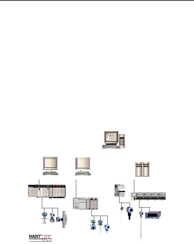
Rockwell Automation and Endress+Hauser have strengthened their strategic alliance to provide complete process automation solutions that use best-in-class instrumentation, software, and control systems.
There are hundreds of different components in a typical plant: controllers, remote I/O, electrical drives, safety equipment, and sensors. Each must be integrated, configured and optimized during start-up and operation. Recognizing the challenges this creates, Rockwell Automation and Endress+Hauser are focused on providing you with scalable, off-the-shelf solutions.
To supply robust system solutions, Rockwell Automation pre-tests many thirdparty manufactured HART, FOUNDATION Fieldbus, and Profibus field devices in the system test laboratory for compatibility with the Integrated Architecture based plant automation system. Each field device is connected to the Rockwell Automation Integrated Architecture based system and is subjected to interoperability testing procedures similar to operating procedures in your plant. The results of each field test are recorded in a test report for integration planning purposes.
For Endress+Hauser field devices, an additional step provides an “Integration Document” and “Interoperability Statement” for each tested instrument. The Integration Document provides information on installation, configuration, startup, and operation of the integrated system. The Interoperability Statement is assurance that the Endress+Hauser field device meets Integrated Architecture system interoperability performance measures, as jointly established by Rockwell Automation and Endress+Hauser and verified through completion of common test procedures performed by either company. Both the Integration Document and Interoperability Statement ensure a no risk solution highlighted by ease of integration and optimum performance.
Rockwell Automation Publication PROCES-UM002A-EN-P - July 2014 |
7 |

Preface
The overall mission of the alliance is to provide you with proven solutions that combine field instrumentation with fieldbus networks, such as HART, FOUNDATION Fieldbus, and Profibus networks, with asset management capabilities and Rockwell Automation’s system capabilities to provide a total engineered solution.
Through preferred integration and support of increasing requirements for plantwide control, the alliance offers the following benefits:
•Reduced integration costs throughout engineering, commissioning, and start-up
•Optimized plant availability and output
•Ensured product quality and consistency
•Optimized traceability to meet regulatory demands
•Predictive maintenance through intelligent instruments
Application Overview
For new construction, process improvements at an existing plant, or operating cost reductions, the alliance delivers the following:
•Integration reduces risk, reduces integration costs, and protects investment with assured interoperability. Both companies believe open systems and standardized interfaces bring maximum benefits.
•Advanced diagnostics with plant-wide support offers better visibility of plant health and easier access to instrument diagnostics, which leads to faster troubleshooting and improves decision-making.
•Collaborative lifecycle management to design, engineer, and startup systems faster. This collaboration increases productivity, manages information about instrumentation assets, optimizes plant assets, and results in a complete lifecycle management solution.
This document provides a step-by-step approach to integrating Endress+Hauser devices into a Rockwell Automation Integrated Architecture for Process Control system.
This Section |
Describes |
|
|
Application overview |
Details about the field instrument and control system. |
|
|
System details |
Specifications on the required hardware and software components. |
|
|
Installation |
How to: |
|
• Connect the measurement instrument to the HART I/O module. |
|
• Connect a HART handheld device. |
|
|
Configuration |
How to: |
|
• Configure the HART I/O module. |
|
• Configure the measurement instrument and manage parameters. |
|
|
Visualization |
How to implement and configure a graphical display of device information. |
|
|
8 |
Rockwell Automation Publication PROCES-UM002A-EN-P - July 2014 |
Preface
The tested HART devices are the following:
•Promass 83 flowmeter
•Promag 53 flowmeter
•Proline t-mass 65 flowmeter
•Prosonic S transmitter
•Prowirl 73 flowmeter
•Levelflex M guided level-radar
•Micropilot M level-radar
•Prosonic M ultrasonic level
•Liquiline M CM42 transmitter
•Cerabar S pressure transmitter
•Deltabar S differential pressure
•iTEMP TMT162 temperature transmitter
•iTEMP TMT182 temperature transmitter
The ControlLogix platform provides a full range of input and output modules to span a wide variety of applications. The ControlLogix architecture uses producer/consumer technology, allowing input information and output status to be shared by all ControlLogix controllers in the system.
Integrated Asset Management
Engineering |
Operator |
|
|
|
|
|
|
|
|
|
|
|
|
|
|
|
|
|
|
|
|
|
|
|
|
|
|
|
|
|
|||||||||||
|
|
|
|
|
|
|
|
|
|
|
|
|
|
|
|
|
|
|
|
|
|
|
|
|
|
|
|
|
|||||||||||||
Workstation (EWS) |
Workstation (OWS) |
|
|
|
|
|
Process Automation |
||||||||||||||||||||||||||||||||||
|
|
|
|
|
|
|
|
|
|
|
|
|
|
|
|
|
|
|
|||||||||||||||||||||||
|
|
|
|
|
|
|
|
|
|
|
|
|
|
|
|
|
|
|
System Server (PASS) |
||||||||||||||||||||||
|
|
|
|
|
|
|
|
|
|
|
|
|
|
|
|
|
|
|
|
|
|
|
|
|
|
|
|
|
|
|
|
|
|
|
|
|
|
|
|
|
|
|
|
|
|
|
|
|
|
|
|
|
|
|
|
|
|
|
|
|
|
|
|
|
|
|
|
|
|
|
|
|
|
|
|
|
|
|
|
|
|
|
|
|
|
|
|
|
|
|
|
|
|
|
|
|
|
|
|
|
|
|
|
|
|
|
|
|
|
|
|
|
|
|
|
|
|
|
|
|
|
|
|
|
|
|
|
|
|
|
|
|
|
|
|
|
|
|
|
|
|
|
|
|
|
|
|
|
|
|
|
|
|
|
|
|
|
|
|
|
|
|
|
|
|
|
|
|
|
|
|
|
|
|
|
|
|
|
|
|
|
|
|
|
|
|
|
|
|
|
|
|
|
|
|
|
|
|
|
|
|
|
|
|
|
|
|
|
|
|
|
|
|
|
|
|
|
|
|
|
|
|
|
|
|
|
|
|
|
|
|
|
|
|
|
|
|
|
|
|
|
|
|
|
|
|
|
|
|
|
|
|
|
|
|
|
|
|
|
|
|
|
|
|
|
|
|
|
|
|
|
|
|
|
|
|
|
|
|
|
|
|
|
|
|
|
|
|
|
|
|
|
|
POINT I/O |
FLEX I/O System |
System |
|
ControlLogix |
|
System |
|
CompactLogix |
|
System |
|
Rockwell Automation Publication PROCES-UM002A-EN-P - July 2014 |
9 |

Preface
|
Control System |
|
The control system includes these components: |
|
|
Component |
Description |
|
|
Controller |
The ControlLogix controller is a modular, high performance controller, that uses RSLogix 5000 programming software |
|
to configure, program, and monitor a system. The ControlLogix controller is certified by TUV for SIL 1 and SIL 2 |
|
applications. |
|
|
HART I/O module |
The HART analog I/O module converts to or from 4...20 mA analog signals and the digital values used in the controller. |
|
The I/O module automatically collects dynamic process data from the HART field instrument. The I/O module also |
|
bridges HART messages from CIP clients to HART field instruments. |
|
|
Programming software |
RSLogix 5000 programming software is the design and configuration tool for HART I/O that includes status and |
|
diagnostic information. The software has predefined data structures for status and configuration. A common tag |
|
database in the controller allows HMI development to directly reference I/O and controller tags without the need to |
|
manage another database in your HMI software. |
|
|
Operating software |
FactoryTalk View Site Edition software is an HMI software program for monitoring, controlling, and acquiring data from |
|
manufacturing operations throughout an enterprise. A generic display provides a graphical representation via |
|
faceplates of the field instrument connected to the HART input module. |
|
|
Asset management software |
FactoryTalk AssetCentre software and FieldCare software are options asset management options for configuring and |
|
managing the intelligent field devices in your plant. |
|
• Support Ethernet, HART, and Profibus networks. |
|
• Support Endress+Hauser field instruments. |
|
• Integrate third-party devices, such as actuators, I/O systems, and sensors that support the FDT standard. |
|
• Ensure full functionality for all devices with DTMs. |
|
• Offer generic profile operation for any third-party fieldbus device that does not have a vendor DTM. |
|
|
HART Handheld Device (Optional)
The Field Xpert handheld device is an industrial PDA with integrated 3.5" touch screen based on Windows Mobile. The PDA meets the needs and requirements of the process industry with protection from static electricity, water and dust with shockproof housing. It is available in different versions for operation both inside and outside of explosion hazardous areas.
10 |
Rockwell Automation Publication PROCES-UM002A-EN-P - July 2014 |
Preface
System Details
These components and specifications are recommended for preferred integration.
Hardware Components
Component |
Catalog Number |
|
|
HART device |
See appropriate appendix |
|
|
ControlLogix controller |
1756-L7 controllers |
|
|
HART input module (select any one) |
1756-IF8H |
|
|
|
1756-IF8IH |
|
|
|
1756-IF16H |
|
|
|
1794-IF8H |
|
|
|
1769sc-IF4IH |
|
|
|
1734sc-IE2CH |
|
|
|
1734sc-IE4CH |
|
|
Software Components
Component |
Catalog Number |
|
|
|
|
RSLogix 5000 Enterprise Series programming software, |
9324-RLD700NXENE |
|
Professional edition |
|
|
Includes: |
|
|
• |
RSLinx Classic software |
|
• |
RSLinx Enterprise software |
|
|
|
|
FactoryTalk View Site Edition (SE) software |
9701-VWSXXXXXENE |
|
|
|
|
FactoryTalk AssetCentre softare |
9515-ASTCAPXXXXX |
|
|
|
|
FieldCare Standard Asset Management software (optional) |
SFE551 |
|
Includes: |
|
|
• |
DTM library |
|
|
|
|
RSLinx Communication DTM software (optional) |
1756-Backplane |
|
|
|
|
For specifications of the engineering workstation (EWS) and operator workstation (OWS), see the Integrated Architecture for Process Control System Recommendations Manual, publication PROCES-RM001.
Rockwell Automation Publication PROCES-UM002A-EN-P - July 2014 |
11 |

Preface
Performance Considerations
Additional Resources
Keep in mind these considerations when integrating HART instruments:
•The HART communication protocol has a relatively slow baud rate at 1200/2400 bits per second.
•The 1756-IF8H HART module executes one HART command per instrument at a time. Analog (4-20ma) data are delivered from all channels simultaneously.
•The time of execution for Universal Command 3 is estimated from 200...600 ms, but varies based on the complexity and response time of the instrument.
•Upload and download time of instrument parameters to and from FieldCare software can take several minutes depending on the instrument.
These documents contain additional information concerning related products from Rockwell Automation.
Resource |
Description |
|
|
Control System Components |
|
|
|
ControlLogix Controllers User Manual, publication 1756-UM001 |
How to install, configure, operate, and maintain a ControlLogix controller. |
|
|
ControlLogix Analog HART I/O Modules User Manual, publication 1756-UM533 |
How to install, configure, operate, and maintain a 1756-IF8H input module. |
|
|
Accessing HART Device Parameters using CIP Messages, Knowledgebase document (Login |
How to use MSG instructions in controller logic to access instrument parameters. |
required. Please contact your sales representative.) |
|
|
|
Operator Components |
|
|
|
Add-On Instructions and Faceplates for Visualizing HART Instrument Data in FactoryTalk |
How to implement the HART Add-On-Instruction in controller logic to work with the |
View SE, Knowledgebase document (Login required. Please contact your sales |
FactoryTalk View faceplates for HART instruments. |
representative.) |
|
|
|
FactoryTalk View Site Edition User's Guide Volume 1, publication VIEWSE-UM004 |
How to design, develop, and deploy FactoryTalk View SE applications. |
|
|
FactoryTalk View Site Edition User's Guide Volume 2, publication VIEWSE-UM005 |
|
|
|
Faceplates, Add-On Instructions, project files, etc. (Login required. Please contact your |
Download AOIs, Faceplates and Global Object graphics, and project files. |
sales representative.) |
|
|
|
www.products.endress.com/fieldcare |
Information about FieldCare Asset Management software. |
|
|
www.products.endress.com/dtm-download |
Information about field instrument DTMs. |
|
|
Process Control Information |
|
|
|
Integrated Architecture for Process Control System Recommendations Manual, |
Process system recommendations that organize Rockwell Automation products |
publication PROCES-RM001 |
functionally as system elements, which can then be applied in proven, scalable |
|
configurations for continuous and batch control. |
|
|
http://www.rockwellautomation.com/process |
Information about Rockwell Automation process control and Integration Documents. |
|
|
http://literature.rockwellautomation.com |
Available Rockwell Automation publications, including Integration Documents. |
|
|
http://www.endress.com |
Information about Endress+Hauser field instruments. |
|
|
You can view or download publications at http:/www.rockwellautomation.com/literature/. To order paper copies of technical documentation, contact your local Allen-Bradley distributor or Rockwell Automation sales representative.
12 |
Rockwell Automation Publication PROCES-UM002A-EN-P - July 2014 |

Chapter 1
Connect a 2-Wire Field
Instrument
Installation
Topic |
Page |
|
|
Connect a 2-Wire Field Instrument |
13 |
|
|
Connect a 4-Wire Field Instrument |
17 |
|
|
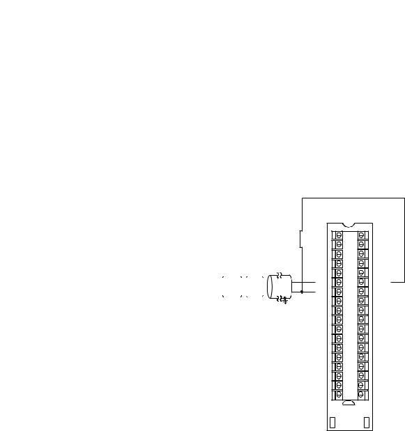
HART communication is active only with current inputs. Connect a 2-wire field instrument to any channel of the HART input module in a 2-wire configuration for current input.
HART devices that support 2-wire connections include the following.
Device |
See appendix |
|
|
Prowirl 73 flowmeter |
Appendix D on page 97 |
|
|
Levelflex M guided level-radar |
Appendix F on page 109 |
|
|
Micropilot M level-radar |
Appendix G on page 115 |
|
|
Prosonic M ultrasonic level |
Appendix E on page 103 |
|
|
Liquiline M CM42 transmitter |
Appendix M on page 147 |
|
|
Cerabar S pressure transmitter |
Appendix H on page 119 |
|
|
Deltabar S differential pressure |
Appendix I on page 125 |
|
|
iTEMP TMT162 temperature transmitter |
Appendix K on page 139 |
|
|
iTEMP TMT182 temperature transmitter |
Appendix L on page 143 |
|
|
Rockwell Automation Publication PROCES-UM002A-EN-P - July 2014 |
13 |
Chapter 1 |
Installation |
|
|
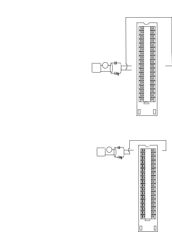
Figure 1 - 2-Wire Connection to 1756-IF8H Input Module
|
2 Wire Current Input |
|
|
|
|
|
|
|
|
IN0+ |
2 |
1 |
I RTN-0 |
|
|
|
IN0- |
4 |
3 |
NC |
|
|
|
IN1+ |
6 |
5 |
I RTN-1 |
|
|
|
IN1- |
8 |
7 |
NC |
|
|
|
RTN |
10 |
9 |
RTN |
|
|
|
IN2+ |
12 |
11 |
I RTN-2 |
|
|
|
IN2- |
14 |
13 |
NC |
|
|
2 Wire |
IN3+ |
16 |
15 |
I RTN-3 |
|
|
HART |
IN3- |
18 |
17 |
NC |
|
|
Device |
||||
24 VDC + |
+ - |
IN4+ |
20 |
19 |
I RTN-4 |
|
|
||||||
Power |
- |
|
|
|
|
|
Supply |
|
IN4- |
22 |
21 |
NC |
|
|
|
|
IN5+ |
24 |
23 |
I RTN-5 |
|
|
|
IN5- |
26 |
25 |
NC |
|
|
|
RTN |
28 |
27 |
RTN |
|
|
|
IN6+ |
30 |
29 |
I RTN-6 |
|
|
|
IN6- |
32 |
31 |
NC |
|
|
|
IN7+ |
34 |
33 |
I RTN-7 |
|
|
|
IN7- |
36 |
35 |
NC |
Figure 2 - 2-Wire Connection to 1756-IF16H Input Module
2 Wire HART Device
2 Wire
XMTR
+ +-
+-
24V DC
Power Supply -
IN0+ |
2 |
1 |
IN0- |
IN1+ |
4 |
3 |
IN1- |
IN2+ |
6 |
5 |
IN2- |
IN3+ |
8 |
7 |
IN3- |
RTN |
10 |
9 |
RTN |
IN4+ |
12 |
11 |
IN4- |
IN5+ |
14 |
13 |
IN5- |
IN6+ |
16 |
15 |
IN6- |
IN7+ |
18 |
17 |
IN7- |
IN8+ |
20 |
19 |
IN8- |
IN9+ |
22 |
21 |
IN9- |
IN10+ |
24 |
23 |
IN10- |
IN11+ |
26 |
25 |
IN11- |
RTN |
28 |
27 |
RTN |
IN12+ |
30 |
29 |
IN12- |
IN13+ |
32 |
31 |
IN13- |
IN14+ |
34 |
33 |
IN14- |
IN15+ |
36 |
35 |
IN15- |
14 |
Rockwell Automation Publication PROCES-UM002A-EN-P - July 2014 |
|
|
|
|
|
|
|
|
|
|
|
|
|
|
|
|
|
|
|
|
Installation |
Chapter 1 |
|
Figure 3 - 2-Wire Connection to 1794-IE8H Input Module |
|
|
|
|
|
|
|
|
|
|||||||||||||
|
|
|
|
|
|
|
|
|
|
|
|
|
|
|
|
|
|
+V |
|
|
|
|
|
|
|
|
|
|
|
|
|
|
|
|
|
|
|
|
|
|
-V |
4 to 20mA |
4 to 20mA |
|
|
|
|
|
|
|
|
|
|
|
|
|
|
|
|
|
|
|
|
+ |
|
Xmit |
Xmit |
|
|
|
|
|
|
|
|
|
|
|
|
|
|
91 Ω |
|
|
|
|
|
|
|
||
Flexbus |
|
Bus |
|
|
|
|
|
|
|
|
|
|
|
|
|
|
|
|
|
|||
|
|
|
|
|
|
|
|
|
|
17V |
|
|
|
|
|
I |
I |
|
||||
|
|
|
|
|
|
|
|
|
|
|
|
|
|
|
|
|
|
|
|
P |
P |
|
|
|
|
|
uC |
|
|
|
|
|
|
|
|
|
|
|
|
|
Sig |
|
|
|
|
|
|
|
|
|
|
|
|
|
|
|
|
|
|
|
|
|
|
|
|
|
|
|
|
|
|
|
|
|
|
|
|
|
|
|
|
|
22 Ω |
|
|
|
|
|
|
||
|
|
|
|
|
|
|
|
|
|
|
|
|
|
|
|
|
|
- |
|
|
|
|
|
|
|
|
|
|
|
|
|
|
|
|
|
|
|
|
|
|
|
|
|
40072 |
|
0 |
1 |
2 |
|
3 |
4 |
5 |
6 |
7 |
8 |
9 |
10 |
11 |
12 |
13 |
14 |
15 |
|
|
|
|
|
|
+ |
|
_ |
|
|
|
+ |
_ |
|
|
+ |
_ |
|
|
|
+ |
|
_ |
|
A |
|
|
|
|
|
|
|
|
|
|
|
|
|
|
|
|
|
|||||||||
|
|
|
|
|
|
|
|
|
|
|
|
|
|
|
|
|
|
|
||||
Ch0 |
|
|
|
|
Ch1 |
|
|
|
Ch2 |
|
|
|
Ch3 |
|
|
|
|
|||||
16 |
17 |
18 |
19 |
20 |
21 |
22 |
23 |
24 |
25 |
26 |
27 |
28 |
29 |
30 |
31 |
32 |
|
33 |
|
|
|
|
Chassis + |
_ |
|
|
|
+ |
_ |
|
|
+ |
_ |
|
|
+ |
|
_ |
|
|
B |
|
|||
|
|
|
|
|
|
|
|
|
Chassis |
|
|
|||||||||||
Ground |
|
|
|
|
|
|
|
|
|
|
|
|
|
|
|
|
|
|
|
Ground |
|
|
|
Ch4 |
|
|
|
Ch5 |
|
|
|
|
Ch6 |
|
|
|
|
Ch7 |
|
|
|
|
|||
34 |
35 |
36 |
|
37 |
38 |
39 |
40 |
41 |
42 |
43 |
44 |
45 |
46 |
47 |
48 |
49 |
50 |
51 |
|
|
|
|
|
|
|
|
|
|
|
|
|
|
|
|
|
|
|
|
|
|
|
|
|
C |
|
+V |
-V (COM) NC |
|
|
|
|
|
|
|
|
|
|
|
|
|
|
|
NC |
+V -V (COM) |
|
|||
24C dc |
Chassis Grounds for Shields |
24C dc |
|
Supply Out |
|||
Supply In |
|
||
|
|
||
+V = +24V dc = Terminals C-34 and C-50 |
(1794-TB3G shown) |
||
-V = COM = C-35 and C-51 |
|
|
|
Chassis Ground = Terminals B-16, B-33, C-38, C-40…45, and C-47 |
|
||
NC = No connection |
|
|
|
For daisy-chaining: Supply in - C-34 (+) and C-35 (-)
Supply out - C-50 (+) and C-51 (-)
Figure 4 - 2-Wire Connection to 1794-IF8IH Input Module
0 |
1 |
2 |
3 |
4 |
5 |
6 |
7 |
8 |
9 |
10 |
11 |
12 |
13 |
14 |
15 |
|
|
Row A |
|
16 |
17 |
18 |
19 |
20 |
21 |
22 |
23 |
24 |
25 |
26 |
27 |
28 |
29 |
30 |
31 |
32 |
33 |
Row B |
|
34 |
35 |
36 |
37 |
38 |
39 |
40 |
41 |
42 |
43 |
44 |
45 46 |
47 |
48 |
49 |
50 |
51 |
|||
Row C |
|||||||||||||||||||
Label placed at top of wiring area |
|
|
|
||||||||||||||||
|
|
|
|
||||||||||||||||
|
|
|
|
|
|
|
|
|
|
|
|
|
|
|
|
|
|
Row A |
|
|
|
|
|
|
|
|
|
|
|
|
|
|
|
|
|
|
|
Row B |
|
|
|
|
|
|
|
|
|
|
|
|
|
|
|
|
|
|
|
Row C |
|
|
|
|
|
|
|
|
|
|
Current |
|
|
|
|
|
1794-TB3S shown |
||||
|
|
|
|
|
|
|
|
|
input |
|
|
|
|
|
|
|
|
||
Rockwell Automation Publication PROCES-UM002A-EN-P - July 2014 |
15 |
Chapter 1 |
Installation |
|
|
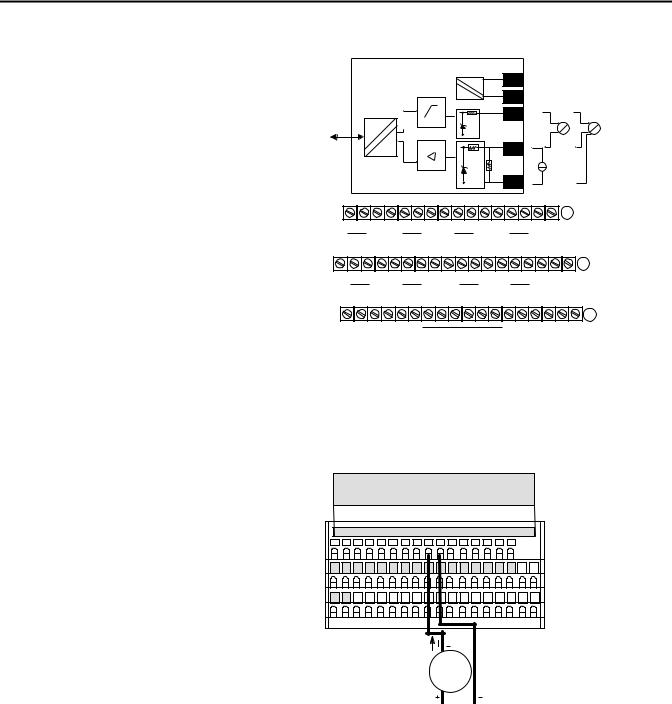
Figure 5 - 2-Wire Connection to 1769sc-IF4IH Input Module |
||||
|
|
|
|
Ch0+ |
2 Wire Current Input |
N/C |
Ch0-iRtn |
||
|
||||
|
|
2 Wire |
N/C |
|
|
|
XMTR |
Ch0- |
|
|
|
+ - |
Ch1+ |
|
24V DC |
|
|||
|
|
|
||
Power |
+ |
|
Ch1-iRtn |
N/C |
Supply |
- |
|
||
|
|
|||
|
|
|
|
|
|
|
|
Ch1- |
Ch2+ |
|
|
|
N/C |
Ch2-iRtn |
|
|
|
Ch2- |
|
|
|
|
Ch3+ |
|
|
|
|
Ch3-iRtn |
N/C |
|
|
|
Ch3- |
N/C |
Figure 6 - 2-Wire Connection to 1734sc-IE2CH Input Module
0 |
1 |
|
|
2 Wire |
IN 0 |
IN 1 |
|
|
Device |
|
|
|
|
|
2 |
3 |
|
|
|
+ 24 |
+ 24 |
|
|
|
|
|
|
|
|
4 |
5 |
|
|
|
COM |
COM |
|
|
|
|
|
|
|
|
6 |
7 |
|
|
|
FGN |
FGN |
|
|
|
|
|
|
|
|
Figure 7 - 2-Wire Connection to 1734sc-IE4CH Input Module
0 |
1 |
|
|
2 Wire |
IN 0 |
IN 1 |
|
|
Device |
|
|
|
|
|
2 |
3 |
|
|
|
IN 2 |
IN 3 |
|
|
|
|
|
|
|
|
4 |
5 |
|
|
|
COM |
+ 24 |
|
|
|
|
|
|
|
|
6 |
7 |
|
|
|
FGN |
FGN |
|
|
|
|
|
|
|
|
16 |
Rockwell Automation Publication PROCES-UM002A-EN-P - July 2014 |
Installation |
Chapter 1 |
|
|
Connect a 4-Wire Field
Instrument
HART communication is active only with current inputs. Connect a 4-wire field instrument to any channel of the HART input module in a 4-wire configuration for current input.
HART devices that support 4-wire connections include the following.
Device |
See appendix |
|
|
Promass 83 flowmeter |
Appendix A on page 83 |
|
|
Promag 53 flowmeter |
Appendix C on page 93 |
|
|
Proline t-mass 65 flowmeter |
Appendix B on page 89 |
|
|
Prosonic S transmitter |
Appendix J on page 133 |
|
|
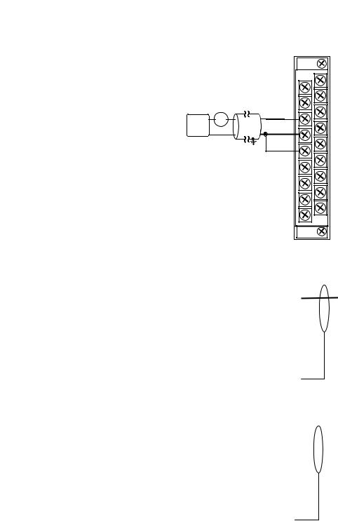
Figure 8 - 4-Wire Connection to 1756-IF8H Input Module
4-wire Current Input
|
|
|
|
|
|
|
|
24V DC + |
|
+ |
+ |
|
|
|
|
|
||||
|
Power |
|
|
|
4-wire |
|
|
Supply - |
|
|
|
MTR |
|
|
|
|
- |
- |
|
|
IN0+ |
2 |
1 |
I RTN-0 |
IN0- |
4 |
3 |
NC |
IN1+ |
6 |
5 |
I RTN-1 |
IN1- |
8 |
7 |
NC |
RTN |
10 |
9 |
RTN |
IN2+ |
12 |
11 |
I RTN-2 |
IN2- |
14 |
13 |
NC |
IN3+ |
16 |
15 |
I RTN-3 |
IN3- |
18 |
17 |
NC |
IN4+ |
20 |
19 |
I RTN-4 |
IN4- |
22 |
21 |
NC |
IN5+ |
24 |
23 |
I RTN-5 |
IN5- |
26 |
25 |
NC |
RTN |
28 |
27 |
RTN |
IN6+ |
30 |
29 |
I RTN-6 |
IN6- |
32 |
31 |
NC |
IN7+ |
34 |
33 |
I RTN-7 |
IN7- |
36 |
35 |
NC |
Rockwell Automation Publication PROCES-UM002A-EN-P - July 2014 |
17 |

Chapter 1 |
Installation |
|
|
Figure 9 - 4-Wire Connection to 1756-IF16H Input Module
4 Wire HART Device
|
|
|
|
|
|
|
24V DC + |
|
+ + |
|
|
|
Power |
|
|
4 Wire |
|
|
Supply - |
|
|
-XMTR- |
|
IN0+ |
2 |
1 |
IN0- |
IN1+ |
4 |
3 |
IN1- |
IN2+ |
6 |
5 |
IN2- |
IN3+ |
8 |
7 |
IN3- |
RTN |
10 |
9 |
RTN |
IN4+ |
12 |
11 |
IN4- |
IN5+ |
14 |
13 |
IN5- |
IN6+ |
16 |
15 |
IN6- |
IN7+ |
18 |
17 |
IN7- |
IN8+ |
20 |
19 |
IN8- |
IN9+ |
22 |
21 |
IN9- |
IN10+ |
24 |
23 |
IN10- |
IN11+ |
26 |
25 |
IN11- |
RTN |
28 |
27 |
RTN |
IN12+ |
30 |
29 |
IN12- |
IN13+ |
32 |
31 |
IN13- |
IN14+ |
34 |
33 |
IN14- |
IN15+ |
36 |
35 |
IN15- |
Figure 10 - 4-Wire Connection to 1794-IF8IH Input Module
0 |
1 |
2 |
3 |
4 |
5 |
6 |
7 |
8 |
9 |
10 |
11 |
12 |
13 |
14 |
15 |
|
|
Row A |
|
16 |
17 |
18 |
19 |
20 |
21 |
22 |
23 |
24 |
25 |
26 |
27 |
28 |
29 |
30 |
31 |
32 |
33 |
Row B |
|
34 |
35 |
36 |
37 |
38 |
39 |
40 |
41 |
42 |
43 |
44 |
45 46 |
47 |
48 |
49 |
50 |
51 |
|||
Row C |
|||||||||||||||||||
Label placed at top of wiring area |
|
|
|
||||||||||||||||
|
|
|
|
||||||||||||||||
|
|
|
|
|
|
|
|
|
|
|
|
|
|
|
|
|
|
Row A |
|
|
|
|
|
|
|
|
|
|
|
|
|
|
|
|
|
|
|
Row B |
|
|
|
|
|
|
|
|
|
|
|
|
|
|
|
|
|
|
|
Row C |
|
Current |
|
|
|
|
|
|
|
|
|
|
|
|
|
|
|
1794-TB3S shown |
|||
input |
|
|
|
|
|
|
|
|
|
|
|
|
|
|
|
|
|
|
|
18 |
Rockwell Automation Publication PROCES-UM002A-EN-P - July 2014 |

Installation |
Chapter 1 |
|
|
Figure 11 - 4-Wire Connection to 1769sc-IF4IH Input Module
24V DC+ |
|
+ |
+ |
|
|||
|
|
||||||
Power |
|
|
4 Wire |
|
|||
Supply - |
|
|
|
XMTR |
|
||
|
|
- |
- |
|
|
||
|
|
|
|
||||
4 Wire Current Input
|
Ch0+ |
|
N/C |
Ch0-iRtn |
|
|
||
N/C |
Ch0- |
|
Ch1+ |
||
Ch1-iRtn |
N/C |
|
Ch1- |
Ch2+ |
|
N/C |
Ch2-iRtn |
|
Ch2- |
||
Ch3+ |
||
Ch3-iRtn |
N/C |
|
Ch3- |
N/C |
Figure 12 - 4-Wire Connection to 1734sc-IE2CH Input Module
|
4 Wire |
|
|
0 |
1 |
AC/DC Pwr |
Device |
|
|
IN 0 |
IN 1 |
|
|
|
|
|
|
|
|
|
|
|
|
|
|
|
|
2 |
3 |
|
|
|
|
+ 24 |
+ 24 |
|
|
|
|
|
|
|
|
|
|
4 |
5 |
|
|
|
|
COM |
COM |
|
|
|
|
|
|
|
|
|
|
6 |
7 |
|
|
|
|
FGN |
FGN |
|
|
|
|
|
|
Figure 13 - 4-Wire Connection to 1734sc-IE4CH Input Module
|
|
4 Wire |
|
|
0 |
1 |
AC/DC Pwr |
Device |
|
|
IN 0 |
IN 1 |
|
|
|
|
|
|
|
|
|
|
|
|
|
2 |
3 |
|
|
|
|
|
IN 2 |
IN 3 |
|
|
|
|
|
|
|
|
|
|
|
|
4 |
5 |
|
|
|
|
|
COM |
+ 24 |
|
|
|
|
|
|
|
|
|
|
|
|
6 |
7 |
|
|
|
|
|
FGN |
FGN |
|
|
|
|
|
|
|
Rockwell Automation Publication PROCES-UM002A-EN-P - July 2014 |
19 |

Chapter 1 |
Installation |
|
|
Notes:
20 |
Rockwell Automation Publication PROCES-UM002A-EN-P - July 2014 |
Chapter 2
Configure the HART Device in RSLogix 5000
Programming Software
Configure a HART Input
Module in a ControlLogix
System
Topic |
Page |
|
|
Configure a HART Input Module in a ControlLogix System |
21 |
|
|
Configure a HART Input Module in a Compact I/O System |
27 |
|
|
Configure a HART Input Module in a FLEX I/O System |
29 |
|
|
Configure a HART Input Module in a POINT I/O System |
31 |
|
|
The examples in this chapter use RSLogix 5000 programming software, version 20.
In RSLogix 5000 software, you must have a project open with a ControlLogix controller already configured. Make sure the project path is set to the correct controller.
Use RSWHO Active in RSLogix 5000 software to verify that the controller, HART input module, and devices are active.
Rockwell Automation Publication PROCES-UM002A-EN-P - July 2014 |
21 |

Chapter 2 Configure the HART Device in RSLogix 5000 Programming Software
To configure the I/O module, follow these steps within the configuration tree.
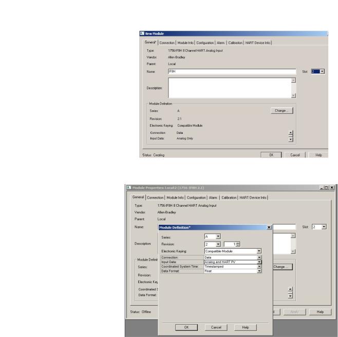
1.From the configuration tree, right click the 1756 backplane and choose New Module.
If the controller communicates with the I/O module over a network, the network interfaces must be added to the configuration tree before adding the I/O module.
2. From the list, select the 1756-IF8H input module.
22 |
Rockwell Automation Publication PROCES-UM002A-EN-P - July 2014 |
Configure the HART Device in RSLogix 5000 Programming Software |
Chapter 2 |
|
|
3. On the General tab, enter the configuration information for the module.
4. Click Change.
5.For Input Data, choose Analog and HART PV.
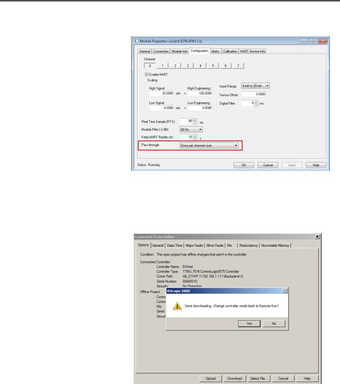
6.On the Configuration tab, enable HART for each channel connected to a device.
Each channel must be enabled to pass HART data to the controller.
Rockwell Automation Publication PROCES-UM002A-EN-P - July 2014 |
23 |
Chapter 2 Configure the HART Device in RSLogix 5000 Programming Software
7.On the Configuration tab, for Passthrough, choose Once per channel scanned.
This passthrough selection is the fastest and best for asset management software.
8.When complete, click OK.
9.Click Download to go online.
24 |
Rockwell Automation Publication PROCES-UM002A-EN-P - July 2014 |
Configure the HART Device in RSLogix 5000 Programming Software |
Chapter 2 |
|
|
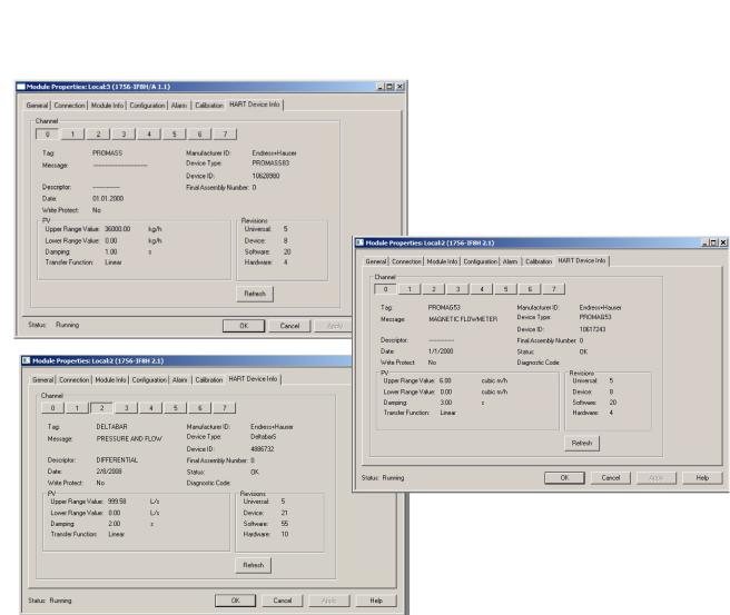
10.From the HART Device Info tab in the HART module properties, verify that the instrument is connected.
|
|
25 |
Rockwell Automation Publication PROCES-UM002A-EN-P - July 2014 |
||
Chapter 2 Configure the HART Device in RSLogix 5000 Programming Software
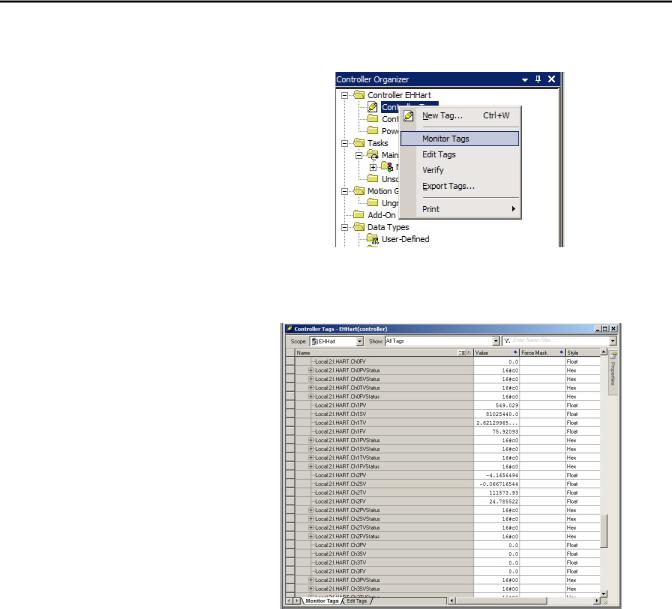
11.Check Controller Tags to verify that the HART instrument is connected and passing data.
A connected instrument displays values in the PV, SV, TV, and FV fields. This tag example shows that the HART input module is in slot 6.
26 |
Rockwell Automation Publication PROCES-UM002A-EN-P - July 2014 |

Configure the HART Device in RSLogix 5000 Programming Software |
Chapter 2 |
|
|
Configure a HART Input
Module in a Compact I/O
System
If HART data is not present, make sure the HART function is enabled.
Use RSWHO Active in RSLogix 5000 software to verify that the controller, HART input module, and devices are active.
This example has a 1769-L35E CompactLogix controller and the Spectrum 1769sc-IF4IH module and uses the Spectrum sample ACD file.
Rockwell Automation Publication PROCES-UM002A-EN-P - July 2014 |
27 |
Chapter 2 Configure the HART Device in RSLogix 5000 Programming Software
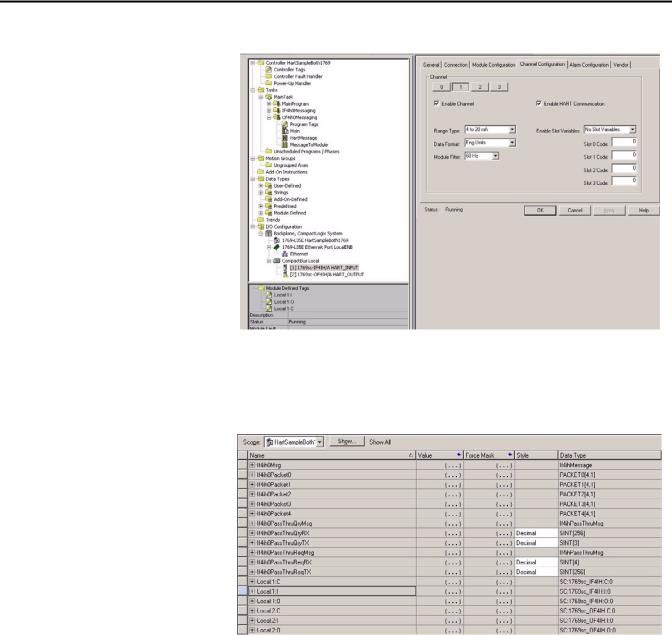
The Spectrum 1769sc-IF4IH is configured as shown.
Make sure that Enable Channel and Enable HART Communication are both checked.
The Spectrum 1769sc-IF4IH has these controller tags.
28 |
Rockwell Automation Publication PROCES-UM002A-EN-P - July 2014 |

Configure the HART Device in RSLogix 5000 Programming Software |
Chapter 2 |
|
|
Configure a HART Input
Module in a FLEX I/O System
This example shows the PV values from the device mapped to the data structure.
In RSLogix 5000 software, you must have a project open with a controller already configured. Make sure the project path is set to the correct controller.
Use RSWHO Active in RSLogix 5000 software to verify that the controller, HART input module, and devices are active.
To configure the I/O module, follow these steps within the configuration tree. This example assumes you have a 1756-ENBT interface and a 1794-AENT adapter.
1.From the configuration tree, right click the 1794-AENT adapter and choose New Module.
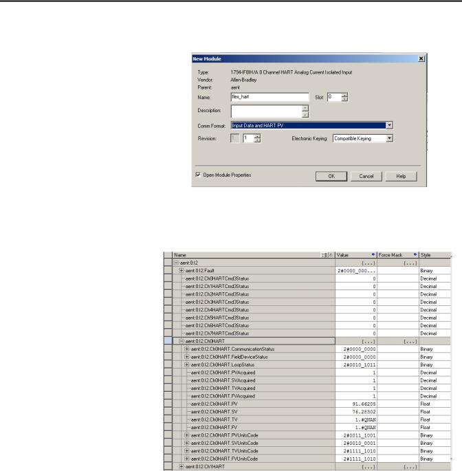
2.From the list, select the HART input module and click Create.
Rockwell Automation Publication PROCES-UM002A-EN-P - July 2014 |
29 |
Chapter 2 Configure the HART Device in RSLogix 5000 Programming Software
3.Enter the configuration information for the module and choose the HART communication format.
4.Click OK.
5.Go online and check the controller tags to make sure the device is connected.
30 |
Rockwell Automation Publication PROCES-UM002A-EN-P - July 2014 |
Loading...