


 Loading...
User Manual
EtherNet/IP Network Configuration
Catalog Numbers 1756-ENBT, 1756-EN2F, 1756-EN2T, 1756-EN2TR, 1756-EN2TXT, 1756-EN3TR, 1756-EN2TSC, 1756-EN2TRXT, 1768-ENBT, 1769-L23E-QB1B, 1769-L23E-QBFC1B, 1769-L32E, 1769-L35E, 1769-AENTR, 1783-ETAP, 1783-ETAP1F, 1783-ETAP2F, 1794-AENT, 20-COMM-E, 22-COMM-E, 1734-AENT, 1734-AENTR
Important User Information
Read this document and the documents listed in the additional resources section about installation, configuration, and operation of this equipment before you install, configure, operate, or maintain this product. Users are required to familiarize themselves with installation and wiring instructions in addition to requirements of all applicable codes, laws, and standards.
Activities including installation, adjustments, putting into service, use, assembly, disassembly, and maintenance are required to be carried out by suitably trained personnel in accordance with applicable code of practice.
If this equipment is used in a manner not specified by the manufacturer, the protection provided by the equipment may be impaired.
In no event will Rockwell Automation, Inc. be responsible or liable for indirect or consequential damages resulting from the use or application of this equipment.
The examples and diagrams in this manual are included solely for illustrative purposes. Because of the many variables and requirements associated with any particular installation, Rockwell Automation, Inc. cannot assume responsibility or liability for actual use based on the examples and diagrams.
No patent liability is assumed by Rockwell Automation, Inc. with respect to use of information, circuits, equipment, or software described in this manual.
Reproduction of the contents of this manual, in whole or in part, without written permission of Rockwell Automation, Inc., is prohibited.
Throughout this manual, when necessary, we use notes to make you aware of safety considerations.
WARNING: Identifies information about practices or circumstances that can cause an explosion in a hazardous environment, which may lead to personal injury or death, property damage, or economic loss.
ATTENTION: Identifies information about practices or circumstances that can lead to personal injury or death, property damage, or economic loss. Attentions help you identify a hazard, avoid a hazard, and recognize the consequence.
IMPORTANT Identifies information that is critical for successful application and understanding of the product.
Labels may also be on or inside the equipment to provide specific precautions.
SHOCK HAZARD: Labels may be on or inside the equipment, for example, a drive or motor, to alert people that dangerous voltage may be present.
BURN HAZARD: Labels may be on or inside the equipment, for example, a drive or motor, to alert people that surfaces may reach dangerous temperatures.
ARC FLASH HAZARD: Labels may be on or inside the equipment, for example, a motor control center, to alert people to potential Arc Flash. Arc Flash will cause severe injury or death. Wear proper Personal Protective Equipment (PPE). Follow ALL Regulatory requirements for safe work practices and for Personal Protective Equipment (PPE).
Allen-Bradley, CompactLogix, ControlLogix, DriveLogix, FactoryTalk, FLEX, FlexLogix, Logix5000, NetLinx, PanelBuilder, PanelView, PLC-5, POINT I/O, PowerFlex,, Rockwell Automation, RSLinx, RSLogix, RSView, SLC, and Studio 5000 are trademarks of Rockwell Automation, Inc.
Trademarks not belonging to Rockwell Automation are property of their respective companies.

Summary of Changes
Introduction
Updated Information
This release of this document contains new and updated information. To find new and updated information, look for change bars, as shown next to this paragraph.
The document contains these changes.
Topic |
Page |
|
|
Added the 1769-AENTR to system-level figures |
12, 34, 36, 45 |
|
|
Added information about the 1769-AENTR diagnostic web pages |
116 |
|
|
Added information about troubleshooting the 1769-AENTR with the web pages |
136 |
|
|
Additional, less-significant changes have been made throughout the document. Change bars mark all changes.
For more information about publications that assist you when you use the products described in this publication, see Additional Resources on page 10.
Rockwell Automation Publication ENET-UM001L-EN-P - March 2014 |
3 |

Summary of Changes
Notes:
4 |
Rockwell Automation Publication ENET-UM001L-EN-P - March 2014 |

|
|
Table of Contents |
Preface |
About This Manual . . . . . . . . . . . . . . . . . . . . . . . . . . . . . . . . |
. . . . . . . . . . . . . . . . 9 |
|
Studio 5000 Environment . . . . . . . . . . . . . . . . . . . . . . . . . . . |
. . . . . . . . . . . . . . . 9 |
|
Additional Resources . . . . . . . . . . . . . . . . . . . . . . . . . . . . . . . . |
. . . . . . . . . . . . . 10 |
EtherNet/IP Overview
Configure a Workstation to Operate on an EtherNet/IP Network
Configure an EtherNet/IP Communication Module to Operate on the Network
Chapter 1
EtherNet/IP Communication Modules in a Control System. . . . . . . . . 11
Chapter 2
Configure the Ethernet Communication Driver in RSLinx Software . 14
Chapter 3
Determine Network Parameters . . . . . . . . . . . . . . . . . . . . . . . . . . . . . . . . . . . 17
Set the Network IP Address on a Module . . . . . . . . . . . . . . . . . . . . . . . . . . 18 Set the Network IP Address with the Rotary Switches . . . . . . . . . . . 20 Set the Network IP Address with the BOOTP/DHCP Server. . . . 21 Set the Network IP Address with RSLinx Software or the
Studio 5000 Environment. . . . . . . . . . . . . . . . . . . . . . . . . . . . . . . . . . . . . 24 Reset the Module IP Address to Factory Default Value . . . . . . . . . . 29 Duplicate IP Address Detection . . . . . . . . . . . . . . . . . . . . . . . . . . . . . . . . . . . 29 Duplicate IP Address Resolution . . . . . . . . . . . . . . . . . . . . . . . . . . . . . . 30
IP Address Swapping . . . . . . . . . . . . . . . . . . . . . . . . . . . . . . . . . . . . . . . . . . . . . 30 DNS Addressing . . . . . . . . . . . . . . . . . . . . . . . . . . . . . . . . . . . . . . . . . . . . . . . . . 31 Use EtherNet/IP Communication Modules in a Logix5000
Controller Application . . . . . . . . . . . . . . . . . . . . . . . . . . . . . . . . . . . . . . . . . . . 32
Configure a Supervisor on a Devicelevel Ring Network
Chapter 4
DLR Nodes. . . . . . . . . . . . . . . . . . . . . . . . . . . . . . . . . . . . . . . . . . . . . . . . . . . . . . 34 Supervisor Node . . . . . . . . . . . . . . . . . . . . . . . . . . . . . . . . . . . . . . . . . . . . . 34 Ring Node . . . . . . . . . . . . . . . . . . . . . . . . . . . . . . . . . . . . . . . . . . . . . . . . . . . 35
Construct the Physical Network. . . . . . . . . . . . . . . . . . . . . . . . . . . . . . . . . . . 36
Configure Supervisor Nodes on a DLR Network . . . . . . . . . . . . . . . . . . . 37 Configure a Ring Supervisor in the Studio 5000 Environment. . . . 37 Enable Ring Supervisor in the Studio 5000 Environment . . . . . . . . 40
Configure and Enable a Ring Supervisor in RSLinx
Classic Software . . . . . . . . . . . . . . . . . . . . . . . . . . . . . . . . . . . . . . . . . . . . . . 43
Complete the Physical Connections of the Network . . . . . . . . . . . . . . . . 45 Verify Supervisor Configuration. . . . . . . . . . . . . . . . . . . . . . . . . . . . . . . . . . . 46
Rockwell Automation Publication ENET-UM001L-EN-P - March 2014 |
5 |

Table of Contents
Control I/O
Interlocking and Data Transfer between Controllers
Chapter 5
Set Up the Hardware . . . . . . . . . . . . . . . . . . . . . . . . . . . . . . . . . . . . . . . . . . . . . 47
Add Distributed I/O . . . . . . . . . . . . . . . . . . . . . . . . . . . . . . . . . . . . . . . . . . . . . 48
Add an I/O Module . . . . . . . . . . . . . . . . . . . . . . . . . . . . . . . . . . . . . . . . . . 50
Select a Communication Format. . . . . . . . . . . . . . . . . . . . . . . . . . . . . . . . . . . 52
Choosing a Direct or Rack-optimized Connection . . . . . . . . . . . . . . 52
Ownership . . . . . . . . . . . . . . . . . . . . . . . . . . . . . . . . . . . . . . . . . . . . . . . . . . . 56
Select a Remote Adapter . . . . . . . . . . . . . . . . . . . . . . . . . . . . . . . . . . . . . . 57
Set the Requested Packet Interval (RPI) . . . . . . . . . . . . . . . . . . . . . . . . . . . . 58
Access Distributed I/O . . . . . . . . . . . . . . . . . . . . . . . . . . . . . . . . . . . . . . . . . . . 59
Chapter 6
Set Up the Hardware . . . . . . . . . . . . . . . . . . . . . . . . . . . . . . . . . . . . . . . . . . . . . 62
Logix5000 Controller Combinations. . . . . . . . . . . . . . . . . . . . . . . . . . . 62
Tag Guidelines for Produced or Consumed Data. . . . . . . . . . . . . . . . . . . . 63 Terminology . . . . . . . . . . . . . . . . . . . . . . . . . . . . . . . . . . . . . . . . . . . . . . . . . 64
Connections for Produced and Consumed Tags . . . . . . . . . . . . . . . . . . . . 64 Produce a Tag . . . . . . . . . . . . . . . . . . . . . . . . . . . . . . . . . . . . . . . . . . . . . . . . . . . . 66 Configure the Produced Tag. . . . . . . . . . . . . . . . . . . . . . . . . . . . . . . . . . . 66 Consume Data Produced by Another Controller. . . . . . . . . . . . . . . . . . . . 68
Add the Producer Controller to the Consumer’s I/O
Configuration . . . . . . . . . . . . . . . . . . . . . . . . . . . . . . . . . . . . . . . . . . . . . . . . 68 Create the Consumed Tag. . . . . . . . . . . . . . . . . . . . . . . . . . . . . . . . . . . . . 70 Guidelines for Message (MSG) Instructions . . . . . . . . . . . . . . . . . . . . . . . . 73 Connections for Messages. . . . . . . . . . . . . . . . . . . . . . . . . . . . . . . . . . . . . . . . . 74 Cache Message Connections. . . . . . . . . . . . . . . . . . . . . . . . . . . . . . . . . . . 74 Enter Message Logic . . . . . . . . . . . . . . . . . . . . . . . . . . . . . . . . . . . . . . . . . . . . . . 75
Add the EtherNet/IP Communication Module to the Local Controller’s I/O Configuration. . . . . . . . . . . . . . . . . . . . . . . . . . . . . . . . 75 Enter a Message. . . . . . . . . . . . . . . . . . . . . . . . . . . . . . . . . . . . . . . . . . . . . . . 78
Configure a MSG Instruction . . . . . . . . . . . . . . . . . . . . . . . . . . . . . . . . . . . . . 79 Communicate with PLC-5 or SLC Controllers . . . . . . . . . . . . . . . . . . . . . 83 Converting between INTs and DINTs . . . . . . . . . . . . . . . . . . . . . . . . . 83 Mapping Tags . . . . . . . . . . . . . . . . . . . . . . . . . . . . . . . . . . . . . . . . . . . . . . . . 84 Receive MSGs from PLC-5 or SLC 500 Controllers . . . . . . . . . . . . . 86
6 |
Rockwell Automation Publication ENET-UM001L-EN-P - March 2014 |

Table of Contents
Send Email
Communicate with PanelView Terminals
Chapter 7
Introduction. . . . . . . . . . . . . . . . . . . . . . . . . . . . . . . . . . . . . . . . . . . . . . . . . . . . . 87
EtherNet/IP Communication Module as an Email Client . . . . . . . . . . . 87
Send Email via a Controller-initiated Message Instruction . . . . . . . . . . . 89
Create String Tags . . . . . . . . . . . . . . . . . . . . . . . . . . . . . . . . . . . . . . . . . . . 89
Enter the Ladder Logic. . . . . . . . . . . . . . . . . . . . . . . . . . . . . . . . . . . . . . . . 92
Configure the MSG Instruction that Identifies the Mail
Relay Server. . . . . . . . . . . . . . . . . . . . . . . . . . . . . . . . . . . . . . . . . . . . . . . . . . 92
Configure the MSG Instruction That Contains the Email Text . . 94
Enter Email Text. . . . . . . . . . . . . . . . . . . . . . . . . . . . . . . . . . . . . . . . . . . . . . . . . 96
Possible Email Status Codes. . . . . . . . . . . . . . . . . . . . . . . . . . . . . . . . . . . . . . . 96
Chapter 8
Set Up the Hardware . . . . . . . . . . . . . . . . . . . . . . . . . . . . . . . . . . . . . . . . . . . . . 99
Logix5000 Controller Combinations . . . . . . . . . . . . . . . . . . . . . . . . . 100
Connections to PanelView Terminals. . . . . . . . . . . . . . . . . . . . . . . . . . . . . 100 Add a PanelView Terminal . . . . . . . . . . . . . . . . . . . . . . . . . . . . . . . . . . . . . . 101
Organize Controller Data for a PanelView Terminal . . . . . . . . . . . . . . . 105 Connections to
FactoryTalk View Applications. . . . . . . . . . . . . . . . . . . . . . . . . . . . . . . . . . . 106
|
Chapter 9 |
|
Diagnostic Web Pages |
1756-EN2TR Module. . . . . . . . . . . . . . . . . . . . . . . . . . . . . . . . . . . . . . . . . . . |
108 |
|
Diagnostic Overview Page. . . . . . . . . . . . . . . . . . . . . . . . . . . . . . . . . . . . |
108 |
|
Ethernet Statistics Web Page . . . . . . . . . . . . . . . . . . . . . . . . . . . . . . . . . |
110 |
|
Connection Manager Cmd Object Info Web Page . . . . . . . . . . . . . |
111 |
|
Ring Statistics Web Page . . . . . . . . . . . . . . . . . . . . . . . . . . . . . . . . . . . . . |
112 |
|
1756-ENBT Module . . . . . . . . . . . . . . . . . . . . . . . . . . . . . . . . . . . . . . . . . . . . |
113 |
|
Diagnostic Overview Page. . . . . . . . . . . . . . . . . . . . . . . . . . . . . . . . . . . . |
113 |
|
Ethernet Statistics . . . . . . . . . . . . . . . . . . . . . . . . . . . . . . . . . . . . . . . . . . . |
115 |
|
1769-AENTR Adapter . . . . . . . . . . . . . . . . . . . . . . . . . . . . . . . . . . . . . . . . . . |
116 |
|
Diagnostic Overview Page. . . . . . . . . . . . . . . . . . . . . . . . . . . . . . . . . . . . |
116 |
|
Ethernet Statistics . . . . . . . . . . . . . . . . . . . . . . . . . . . . . . . . . . . . . . . . . . . |
118 |
Rockwell Automation Publication ENET-UM001L-EN-P - March 2014 |
7 |

Table of Contents
Troubleshoot an EtherNet/IP Communication Module with Diagnostic Web Pages
Index
Chapter 10
Access Web Browser Support. . . . . . . . . . . . . . . . . . . . . . . . . . . . . . . . . . . . . 121
Troubleshoot the
1756-ENBT Communication Module . . . . . . . . . . . . . . . . . . . . . . . . . . . . 123
Diagnostic Overview Statistics . . . . . . . . . . . . . . . . . . . . . . . . . . . . . . . . 123
Message Connections . . . . . . . . . . . . . . . . . . . . . . . . . . . . . . . . . . . . . . . . 126
I/O Connections . . . . . . . . . . . . . . . . . . . . . . . . . . . . . . . . . . . . . . . . . . . . 126
Ethernet Statistics . . . . . . . . . . . . . . . . . . . . . . . . . . . . . . . . . . . . . . . . . . . 127
Troubleshoot the
1756-EN2TR Communication Module . . . . . . . . . . . . . . . . . . . . . . . . . . . 129
Diagnostic Overview Statistics . . . . . . . . . . . . . . . . . . . . . . . . . . . . . . . . 130 Ethernet Statistics . . . . . . . . . . . . . . . . . . . . . . . . . . . . . . . . . . . . . . . . . . . 133
Troubleshoot the
1769-AENTR Adapter . . . . . . . . . . . . . . . . . . . . . . . . . . . . . . . . . . . . . . . . . . 136
Diagnostic Overview Statistics . . . . . . . . . . . . . . . . . . . . . . . . . . . . . . . . 137 Ethernet Statistics . . . . . . . . . . . . . . . . . . . . . . . . . . . . . . . . . . . . . . . . . . . 140 I/O Connections . . . . . . . . . . . . . . . . . . . . . . . . . . . . . . . . . . . . . . . . . . . . 143
Switch Considerations . . . . . . . . . . . . . . . . . . . . . . . . . . . . . . . . . . . . . . . 143 Internet Group Multicast Protocol . . . . . . . . . . . . . . . . . . . . . . . . . . . . 144 Virtual Local Area Networks . . . . . . . . . . . . . . . . . . . . . . . . . . . . . . . . . 145
Port Mirroring . . . . . . . . . . . . . . . . . . . . . . . . . . . . . . . . . . . . . . . . . . . . . . 146
. . . . . . . . . . . . . . . . . . . . . . . . . . . . . . . . . . . . . . . . . . . . . . . . . . . . . . . . . . . . . . . . 147
8 |
Rockwell Automation Publication ENET-UM001L-EN-P - March 2014 |
Preface
About This Manual
Studio 5000 Environment
This manual describes how you can use EtherNet/IP communication modules
with your Logix5000 controller and communicate with various devices on the Ethernet network.
Use this manual if you program applications that use EtherNet/IP networks with these Logix5000 controllers:
•CompactLogix controller
•ControlLogix controller
•SoftLogix controller
Be sure to understand these concepts and tools:
•Use of networking
•Studio 5000 environment
•RSLinx Classic software
•RSNetWorx for EtherNet/IP software
The Studio 5000 Engineering and Design Environment combines engineering and design elements into a common environment. The first element in the Studio
5000 environment is the Logix Designer application. The Logix Designer
application is the rebranding of RSLogix 5000 software and will continue to be the product to program Logix5000 controllers for discrete, process, batch, motion, safety, and drive-based solutions.
The Studio 5000 environment is the foundation for the future of Rockwell
Automation® engineering design tools and capabilities. This environment is the one place for design engineers to develop all of the elements of their control system.
Rockwell Automation Publication ENET-UM001L-EN-P - March 2014 |
9 |

Preface
Additional Resources
These documents contain additional information concerning related products from Rockwell Automation.
Resource |
Description |
|
|
|
|
EtherNet/IP Communication Modules Installation Instructions, |
Provides information about how to complete these tasks with EtherNet/IP communication modules in a Logix5000 |
|
publication ENET-IN002 |
control system: |
|
|
• |
Install the module |
|
• Configure initial application setup |
|
|
• Troubleshoot application anomalies related to EtherNet/IP communication module use |
|
|
|
|
EtherNet/IP Media Planning and Installation Manual |
Provides details about how to use the required media components and how to plan for, install, verify, troubleshoot, |
|
|
and certify your EtherNet/IP network. |
|
|
This manual is available from the Open DeviceNet Vendor Association (ODVA) at: http://www.odva.org. |
|
|
|
|
EtherNet/IP Secure Communication Module User Manual, |
Provides information on setting up authentication, encryption, and firewalls, typical architectures, and diagnostics |
|
publication ENET-UM003 |
for modules equipped with secure communication functionality. |
|
|
|
|
Ethernet Design Considerations Reference Manual, publication |
Provides explanation of the following Ethernet concepts: |
|
ENET-RM002 |
• |
Overview |
|
||
|
• Network layout and components |
|
|
• |
Network infrastructure devices |
|
• |
Network infrastructure features |
|
• |
Protocol |
|
|
|
EtherNet/IP Socket Interface Application Technique, publication |
Describes the socket interface that you can use to program MSG instructions to communicate between a Logix5000 |
|
ENET-AT002 |
controller via an EtherNet/IP module and Ethernet devices that do not support the EtherNet/IP application |
|
|
protocol, such as bar code scanners, RFID readers, or other standard Ethernet devices. |
|
|
|
|
EtherNet/IP Embedded Switch Technology Application Guide, |
Provides details about how to install, configure, and maintain linear and Device-level Ring (DLR) networks by |
|
publication ENET-AP005 |
using Rockwell Automation EtherNet/IP devices equipped with embedded switch technology. |
|
|
|
|
Integrated Architecture and CIP Sync Configuration Application |
Provides information on CIP Sync and the IEEE 1588-2008 Precision Time Protocol. |
|
Technique, publication IA-AT003 |
|
|
|
|
|
Integrated Motion on the EtherNet/IP Network Reference Manual, |
Reference descriptions of the AXIS_CIP_DRIVE attributes and the Studio 5000 Logix Designer application Control |
|
publication MOTION-RM003 |
Modes and Methods |
|
|
|
|
Network Technology Web page, |
Provides information on reference architectures and white papers on networking. |
|
http://www.rockwellautomation.com/rockwellautomation/ |
|
|
products-technologies/network-technology/overview.page? |
|
|
|
|
|
Industrial Automation Wiring and Grounding Guidelines, |
Provides general guidelines for installing a Rockwell Automation industrial system. |
|
publication 1770-4.1 |
|
|
|
|
|
Product Certifications website, http://www.ab.com |
Provides declarations of conformity, certificates, and other certification details. |
|
|
|
|
You can view or download publications at http:/www.rockwellautomation.com/literature/. To order paper copies of technical documentation, contact your local Allen-Bradley distributor or Rockwell Automation sales representative.
10 |
Rockwell Automation Publication ENET-UM001L-EN-P - March 2014 |
Chapter 1
EtherNet/IP Overview
EtherNet/IP Communication
Modules in a Control System
EtherNet/IP networks are communication networks that offer a comprehensive suite of messages and services for many automation applications.
These are examples of applications that use EtherNet/IP networks:
•Real Time Control
•Time Synchronization
•Motion
This open network standard uses off-the-shelf Ethernet communication products to support real-time I/O messaging, information exchange, and general messaging.
EtherNet/IP networks also support CIP Safety, making the simultaneous transmission of safety and standard control data and diagnostics information over a common network possible.
Depending on the type, Rockwell Automation EtherNet/IP communication modules provide some of this functionality:
•Support for messaging, produced/consumed tags, and distributed I/O
•Encapsulate messages within standard TCP/UDP/IP protocol
•Share a common application layer with ControlNet and DeviceNet network protocols
•Interface via RJ45, category 5, unshielded, twisted-pair cable connectors
•Fiber connectors
•Support for half/full duplex 10 Mbps or 100 Mbps operation
•No network scheduling or routing table requirements
Rockwell Automation Publication ENET-UM001L-EN-P - March 2014 |
11 |
Chapter 1 EtherNet/IP Overview
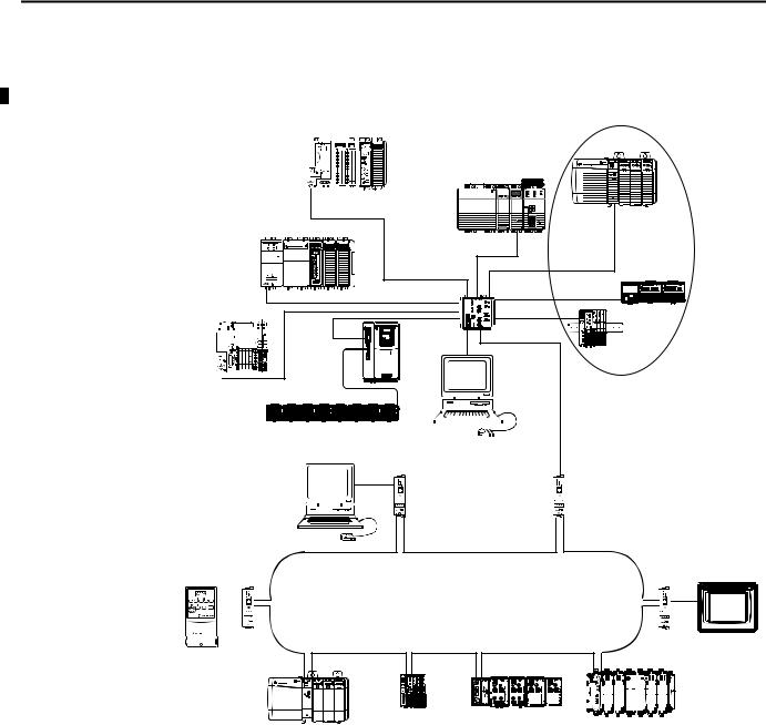
This graphic shows how Rockwell Automation EtherNet/IP communication modules fit into a control system.
Figure 1 - EtherNet/IP Communication Modules in a Control Systems
CompactLogix L2 Controller |
Distributed I/O |
|
1768-L4x |
|
1768-ENBT |
1756-EN2T |
|
|
|
1756 I/O Modules |
CompactLogix L3
Controller
Linear Topology
Switch
1794-AENT
CompactLogix L1 


 1794 I/O Modules
Controller
|
|
|
|
|
|
|
|
PowerFlex |
|
|
|
|
|
|
|
|
|
|
|
|
|
|
|
|
|
|
|
|
|
|
|
|
1734-AENT |
|||||||||||||
|
|
|
|
|
|
|
|
|
|
|
|
|
|
|
|
|
|
|
|
|
|
|
|
|
|
|
|
|
|
|
|
|||||||||||||||
|
|
|
|
|
|
|
|
|
|
|
|
|
|
|
|
|
|
|
|
|
|
|
|
|
|
|
|
|
|
|
|
|||||||||||||||
|
|
|
|
|
|
|
|
|
|
|
|
|
|
|
|
|
|
|
|
|
|
|
|
|
|
|
|
|
|
|
|
1734 I/O Modules |
||||||||||||||
|
|
|
|
|
|
|
|
Drive |
|
|
|
|
|
|
|
|
|
|
|
|
|
|
|
|
|
|
|
|
|
|
|
|
||||||||||||||
|
|
|
|
|
|
|
|
|
|
|
|
|
|
|
|
|
|
|
|
|
|
|
|
|
|
|
|
|
|
|
|
|||||||||||||||
|
|
|
|
|
|
|
|
|
|
|
|
|
|
|
|
|
|
|
|
|
|
|
|
|
|
|
|
|
|
|
|
|
||||||||||||||
|
|
|
|
|
|
|
|
|
|
|
|
|
|
|
|
|
|
|
|
|
|
|
|
|
|
|
|
|
|
|
|
|
|
|
|
|
|
|
|
|
|
|
|
|
|
|
|
|
|
|
|
|
|
|
|
|
|
|
|
|
|
|
|
|
|
|
|
|
|
|
|
|
|
|
|
|
|
|
|
|
|
|
|
|
|
|
|
|
|
|
|
|
|
|
|
|
|
|
|
|
|
|
|
|
|
|
|
|
|
|
|
|
|
|
|
|
|
|
|
|
|
|
|
|
|
|
|
|
|
|
|
|
|
|
|
|
|
|
|
|
|
|
|
|
|
|
|
|
|
|
|
|
|
|
|
|
|
|
|
|
|
|
|
|
|
|
|
|
|
|
|
|
|
|
|
|
|
|
|
|
|
|
|
|
|
|
|
|
|
|
|
|
|
|
|
|
|
|
|
|
|
|
|
|
|
|
|
|
|
|
|
|
|
|
|
|
|
|
|
|
|
|
|
|
|
|
|
|
|
|
|
|
|
|
|
|
|
|
|
|
|
|
|
|
|
|
|
|
|
|
|
|
|
|
|
|
|
|
|
|
|
|
|
|
|
|
|
|
|
|
|
|
|
|
|
|
|
|
|
|
|
|
|
|
|
|
|
|
|
|
|
|
|
|
|
|
|
|
|
|
|
|
|
|
|
|
|
|
|
|
|
|
|
|
|
|
|
|
|
|
|
|
|
|
|
|
|
|
|
|
|
|
|
|
|
|
|
|
|
|
|
|
|
|
|
|
|
|
|
|
|
|
|
|
|
|
|
|
|
|
|
|
|
Workstation |
|
|
|
|
|||||||
|
|
|
|
|
|
|
|
|
|
|
|
|
|
|
|
|
|
|
|
|
|
|
|
|
|
|
|
|
|
|
|
|
|
|
|
|
|
|
|
|
|
|
||||
|
|
|
|
|
|
|
|
|
|
|
|
|
|
|
|
|
|
|
|
|
|
|
|
|
|
|
|
|
|
|
|
|
|
|
|
|
|
|
||||||||
Device-level Ring Topology |
1783-ETAP |
|||||
PowerFlex Drive |
||||||
For more information on using |
|
|
|
|
|
|
EtherNet/IP communication |
|
|
|
|
|
|
|
|
|
|
|
|
|
|
|
|
|
|
|
|
modules and taps in a DLR |
|
|
|
|
|
|
|
|
|
|
|
|
|
|
|
|
|
|
|
|
network, see Configure a |
|
|
|
|
|
|
|
|
|
|
|
|
|
Supervisor on a Device-level Ring |
|
|
|
|
|
|
Network on page 33. |
|
|
|
|
|
|
|
|
|
1783-ETAP |
|
|
|
1783-ETAP |
|
|
|
|
|
|
||
|
|
|
Workstation |
|
|
|
|
|
|
|
|
|
|
|
|
|
|
|
|
|
|
|
|
|
|
|
|
|
|
|
|
1783-ETAP
PanelView Terminal
|
|
|
|
|
|
|
|
|
|
|
|
|
|
|
|
|
|
|
|
|
|
|
|
|
|
|
|
|
|
|
|
|
|
|
|
|
|
|
|
|
|
|
|
|
1734-AENTR |
|
1738-AENTR |
|
|
|
1769-AENTR |
||||||||||||||||||||||
|
|
|
|
|
|
|
|
|
|
|
|
|||||||||||||||||||||||||
1756-EN2TR |
1734 I/O Modules |
|
1738 I/O Modules |
|
|
|
||||||||||||||||||||||||||||||
|
|
|
|
1769 I/O Modules |
||||||||||||||||||||||||||||||||
1756 I/O Modules |
|
|
|
|
|
|
|
|
||||||||||||||||||||||||||||
|
|
|
|
|
|
|
|
|
|
|
|
|
|
|
|
|
|
|
|
|
|
|
|
|
|
|
|
|
||||||||
In this example, these actions can occur over the EtherNet/IP network:
•Controllers produce and consume tags.
•Controllers initiate MSG instructions that send and receive data or configure devices.
•Workstations upload or download projects to the controllers
12 |
Rockwell Automation Publication ENET-UM001L-EN-P - March 2014 |

Chapter 2
Configure a Workstation to Operate on an EtherNet/IP Network
This chapter describes how to configure a workstation to operate on an
EtherNet/IP network.
You must configure an Ethernet communication driver in RSLinx software for the workstation.
A workstation needs the driver to perform these tasks:
•Upload and download Studio 5000 environment project information to controllers over an EtherNet/IP network.
•Configure EtherNet/IP network parameters for devices via RSNetWorx for EtherNet/IP software.
•Collect controller data for electronic operator interfaces, for example,
PanelView Plus terminals, and visualization software, for example,
FactoryTalk View software.
You can choose either of these Ethernet drivers:
•AB_ETHIP
•AB_ETH
Before you add a new driver, confirm these conditions exist:
•Workstation is properly connected to the EtherNet/IP network
•IP address and other network parameters are correctly configured for the workstation
Rockwell Automation Publication ENET-UM001L-EN-P - March 2014 |
13 |
Chapter 2 Configure a Workstation to Operate on an EtherNet/IP Network
Configure the Ethernet
Communication Driver in
RSLinx Software
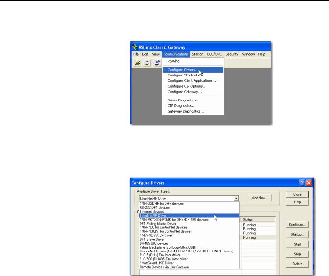
To configure the EtherNet/IP driver, follow these steps.
1. From the Communications menu, choose Configure Drivers.
The Configure Drivers dialog box appears.
2.From the Available Driver Types pull-down menu, choose EtherNet/IP Driver or Ethernet devices and click Add New.
The Add New RSLinx Driver dialog box appears.
14 |
Rockwell Automation Publication ENET-UM001L-EN-P - March 2014 |

Configure a Workstation to Operate on an EtherNet/IP Network |
Chapter 2 |
|
|
3. Type a name for the new driver and click OK.
The Configure driver dialog box appears.
4. Click Browse Local Subnet.
TIP |
To view devices on a different subnet or VLAN from the workstation running |
|
RSLinx software, click Browse Remote Subnet. |
5. Click OK to close the dialog box.
This new driver is available.
Rockwell Automation Publication ENET-UM001L-EN-P - March 2014 |
15 |

Chapter 2 Configure a Workstation to Operate on an EtherNet/IP Network
Notes:
16 |
Rockwell Automation Publication ENET-UM001L-EN-P - March 2014 |

Chapter 3
Configure an EtherNet/IP Communication Module to Operate on the Network
This chapter describes how to configure an EtherNet/IP communication module to operate on an EtherNet/IP network.
Topic |
Page |
|
|
Determine Network Parameters |
17 |
|
|
Set the Network IP Address on a Module |
18 |
|
|
Duplicate IP Address Detection |
29 |
|
|
IP Address Swapping |
30 |
|
|
DNS Addressing |
31 |
|
|
Use EtherNet/IP Communication Modules in a Logix5000 Controller Application |
32 |
|
|
Determine Network
Parameters
To operate an EtherNet/IP network, you must define these parameters.
EtherNet/IP Network Parameter |
Description |
|
|
|
|
IP address |
The IP address uniquely identifies the module. The IP address is in the form xxx.xxx.xxx.xxx where each xxx is a number |
|
|
from 000…254. |
|
|
There are some reserved values that you cannot use as the first octet in the address. These numbers are examples |
|
|
of values you cannot use: |
|
|
• |
001.xxx.xxx.xxx |
|
• |
127.xxx.xxx.xxx |
|
• |
223 to 255.xxx.xxx.xxx |
|
The specific reserved values that cannot be used vary according the conditions of each application. The previous values |
|
|
are only examples of reserved values. |
|
|
|
|
Subnet mask |
Subnet addressing is an extension of the IP address scheme that allows a site to use a single network ID for multiple |
|
|
physical networks. Routing outside of the site continues by dividing the IP address into a net ID and a host ID via the |
|
|
class. Inside a site, the subnet mask is used to redivide the IP address into a custom network ID portion and host ID |
|
|
portion. This field is set to 0.0.0.0 by default. |
|
|
If you change the subnet mask of an already-configured module, you must cycle power to the module for the change |
|
|
to take effect. |
|
|
|
|
Gateway |
A gateway connects individual physical networks into a system of networks. When a node needs to communicate with |
|
|
a node on another network, a gateway transfers the data between the two networks. This field is set to 0.0.0.0 by |
|
|
default. |
|
|
|
|
Rockwell Automation Publication ENET-UM001L-EN-P - March 2014 |
17 |

Chapter 3 Configure an EtherNet/IP Communication Module to Operate on the Network
|
If you use DNS addressing, or reference the module via host name in MSG |
|
|
instructions, define these parameters. |
|
Table 1 - EtherNet/IP Network Parameters for DNS Addressing |
||
|
|
|
EtherNet/IP Network Parameter |
Description |
|
|
|
|
Host name |
A host name is part of a text address that identifies the host for a module. The full text address of a module is |
|
|
host_name.domain_name. |
|
|
|
|
Domain name |
A domain name is part of a text address that identifies the domain in which the module resides. The full text address of a module is |
|
|
host_name.domain_name. The domain name has a 48-character limit. |
|
|
If you specify a DNS server, you must type a domain name. Also, if you send email from the module, some mail relay servers require a |
|
|
domain name during the initial handshake of the SMTP session. |
|
|
|
|
Primary DNS server address |
This identifies any DNS servers used in the network. You must have a DNS server configured if you specified a domain name or a host |
|
|
name in the module’s configuration. The DNS server converts the domain name or host name to an IP address that can be used by the |
|
Secondary DNS server address |
||
network. |
||
|
For more information on DNS addressing, see page 31. |
|
|
|
|
|
Check with your Ethernet network administrator to determine if you need to |
|
|
specify these parameters. |
|
Set the Network IP Address on a Module
Depending on the EtherNet/IP communication module, you can use some or all of these tools to set the network Internet Protocol (IP) address:
•Rotary switches - Switches are physical parts on the module. Remember the following as you read this chapter:
–Some EtherNet/IP communication modules use thumbwheel switches. that function similarly to rotary switches. This chapter uses the term rotary switches to describe both switch types.
–Some EtherNet/IP communication modules do not have rotary switches. If your module does not have switches, skip Set the Network
IP Address with the Rotary Switches on page 20 and go to Set the
Network IP Address with the BOOTP/DHCP Server on page 21.
–1783-ETAPx EtherNet/IP taps use DIP switches to set the network IP address. For more information on how to use the DIP switches, see the publications for those products.
•Bootstrap Protocol (BOOTP)/Dynamic Host Configuration Protocol (DHCP) server
•RSLinx Classic software
•Studio 5000 environment
The module uses these tools sequentially to set the IP address.
18 |
Rockwell Automation Publication ENET-UM001L-EN-P - March 2014 |
Configure an EtherNet/IP Communication Module to Operate on the Network |
Chapter 3 |
|
|
EtherNet/IP communication modules are shipped with this configuration:
•BOOTP/DHCP enabled
•Rotary switches set to 999 - when applicable
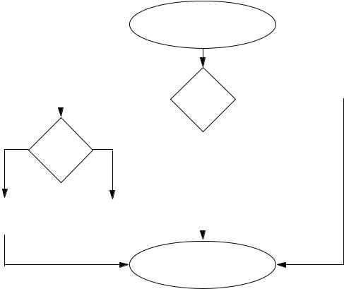
This graphic shows the process used to set your module’s IP address.
Figure 2 - How Your Module’s IP Address is Set
Module Powerup
No |
Switches set |
Yes |
|
from |
|
|
001…254? |
|
|
|
No |
Is DHCP or |
Yes |
|
BOOTP |
|||
|
|
||
|
enabled? |
|
Module uses IP address |
|
Module requests |
|
stored in nonvolatile |
|
address from DHCP/ |
|
|
|||
memory. |
|
BOOTP server. |
|
|
|
|
|
Module has an IP address.
If you need to reset your module’s settings to its factory default settings during normal module operation, Reset the Module IP Address to Factory Default Value on page 29.
The tools are used in this sequence to set the network IP address:
1.Set the Network IP Address with the Rotary Switches
2.Set the Network IP Address with the BOOTP/DHCP Server
3.Set the Network IP Address with RSLinx Software or the Studio 5000 Environment
Rockwell Automation Publication ENET-UM001L-EN-P - March 2014 |
19 |

Chapter 3 Configure an EtherNet/IP Communication Module to Operate on the Network
Set the Network IP Address with the Rotary Switches
This graphic shows the rotary switches on a 1756 EtherNet/IP communication module. The location of the switches is dependant on the module.
At powerup, the module reads the rotary switches to determine if they are set to a valid number for the last portion of the IP address. Valid numbers range from 001…254.
If the settings are a valid number, these conditions result:
•IP address = 192.168.1.xxx (where xxx represents the switch settings)
•Subnet mask = 255.255.255.0
•Gateway address = 0.0.0.0
TIP |
Some modules now provide a gateway address of 192.168.1.1 when the |
|
network address is set with rotary switches. Refer to the product |
|
documentation to determine the correct gateway address the module uses. |
•The module does not have a host name assigned, nor does it use any
Domain Name System
We recommend that you set the rotary switches to a valid number before installing the module.
If either of these conditions exist, the module attempts to use the BOOTP/
DHCP server to set the IP address:
•Rotary switches are not set to a valid number
•Module does not have rotary switches
For more information on using the BOOTP/DHCP server to set the IP address, see page 21.
20 |
Rockwell Automation Publication ENET-UM001L-EN-P - March 2014 |
Configure an EtherNet/IP Communication Module to Operate on the Network |
Chapter 3 |
|
|
Set the Network IP Address with the BOOTP/DHCP Server
The BOOTP/DHCP server is a standalone server you can use to set an IP address. When used, the BOOTP/DHCP server sets an IP address and other Transport Control Protocol (TCP) parameters.
You can use the BOOTP/DHCP server to set the module’s IP address if one of these conditions exists at powerup:
•The module’s rotary switches are not set to a number and the module is BOOTP/DHCP enabled.
•The module does not have rotary switches and the module is BOOTP/ DHCP enabled.
Access the BOOTP/DHCP server from one of these locations:
•Programs > Rockwell Software > BOOTP-DHCP Server
If you have not installed the server, you can download and install it from http://www.ab.com/networks/ethernet/bootp.html.
•Tools directory on the Studio 5000 environment installation CD
IMPORTANT Before you start the BOOTP/DHCP server, make sure you have the module’s hardware (MAC) address. The hardware address is on a sticker on the side of the communication module and uses an address in a format similar to the following:
00-00-BC-14-55-35
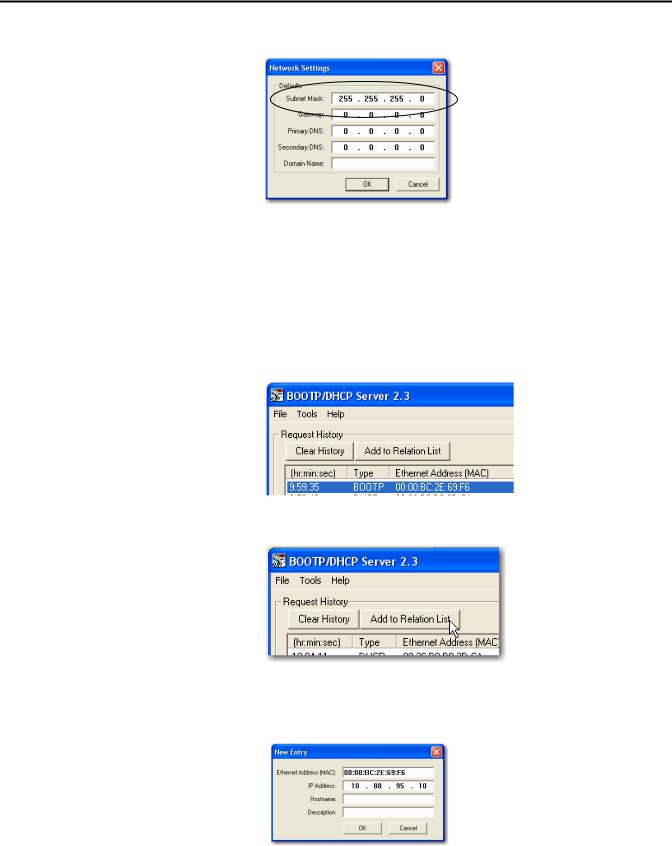
To set the module’s IP address with a BOOTP/DHCP server, follow these steps.
1.Start the BOOTP/DHCP software.
2.From the Tools menu, choose Network Settings.
Rockwell Automation Publication ENET-UM001L-EN-P - March 2014 |
21 |
Chapter 3 Configure an EtherNet/IP Communication Module to Operate on the Network
3. Type the Subnet Mask of the network.
The Gateway address, Primary and/or Secondary DNS address, and
Domain Name fields are optional.
4.Click OK.
The Request History panel appears with the hardware addresses of all modules issuing BOOTP requests.
5.Select the appropriate module.
6. Click Add to Relation List.
The New Entry dialog box appears.
7. Type an IP Address, Hostname, and Description for the module.
8. Click OK.
22 |
Rockwell Automation Publication ENET-UM001L-EN-P - March 2014 |
Configure an EtherNet/IP Communication Module to Operate on the Network |
Chapter 3 |
|
|
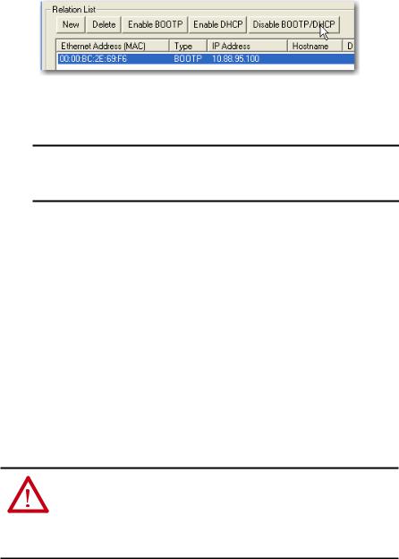
9.To permanently assign this configuration to the module, wait for the module to appear in the Relation List panel and select it.
10.Click Disable BOOTP/DHCP.
When power is recycled, the module uses the assigned configuration and does not issue a BOOTP request.
IMPORTANT If you do not click Disable BOOTP/DHCP, on a power cycle, the host controller clears the current IP configuration and begins sending BOOTP requests again.
Use DHCP Software
Dynamic Host Configuration Protocol (DHCP) software automatically assigns
IP addresses to client stations logging onto a TCP/IP network. DHCP is based on BOOTP and maintains some backward compatibility. The main difference is that BOOTP allows for manual configuration (static), while DHCP allows for both static and dynamic allocation of network addresses and configurations to newly attached modules.
Be cautious when using DHCP software to configure a module. A BOOTP client, such as the EtherNet/IP communication modules, can start from a DHCP server only if the DHCP server is specifically written to also handle BOOTP queries. This is specific to the DHCP software package used. Consult your system administrator to see if a DHCP package supports BOOTP commands and manual IP allocation.
ATTENTION: The EtherNet/IP communication module must be assigned a fixed network address. The IP address of this module must not be dynamically provided.
Failure to observe this precaution may result in unintended machine motion or loss of process control.
Rockwell Automation Publication ENET-UM001L-EN-P - March 2014 |
23 |

Chapter 3 Configure an EtherNet/IP Communication Module to Operate on the Network
Set the Network IP Address with RSLinx Software or the Studio 5000
Environment
This table describes when to set the network IP address with RSLinx software or the Studio 5000 environment.
Conditions |
Software to Use |
Page |
|
|
|
• A BOOTP server is not available |
RSLinx software |
25 |
• The EtherNet/IP communication module is connected to another NetLinx |
|
|
network |
|
|
|
|
|
The Studio 5000 Logix Designer project is online with a controller that |
Studio 5000 environment |
28 |
communicates to or through the EtherNet/IP communication module |
|
|
|
|
|
Consider these factors when you determine how to set the network IP address:
•Network isolation from or integration into the plant/enterprise network
•Network size - For large networks, isolated networks, it might be more convenient and safer to use a BOOTP/DHCP server rather than the Studio 5000 Environment or RSLinx software. The BOOTP/DHCP server also limits the possibility of assigning duplicate IP addresses.
•Company policies and procedures dealing with plant floor network installation and maintenance
•Level of involvement by IT personnel in plant-floor network installation and maintenance
•Type of training offered to control engineers and maintenance personnel
If you use the Rockwell Automation BOOTP or DHCP server in an uplinked subnet where an enterprise DHCP server exists, a module may get an address from the enterprise server before the Rockwell Automation utility even sees the module. You might have to disconnect from the uplink to set the address and configure the module to retain its static address before reconnecting to
the uplink. This is not a problem if you have node names configured in the module and leave DHCP enabled.
24 |
Rockwell Automation Publication ENET-UM001L-EN-P - March 2014 |
Configure an EtherNet/IP Communication Module to Operate on the Network |
Chapter 3 |
|
|
Set the Network IP Address with RSLinx Software
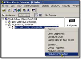
To use RSLinx software to set the communication module’s IP address, follow these steps.
1.From the Communications menu, choose RSWho. The RSWho dialog box appears.
2.Navigate to the Ethernet network.
3.Right-click the EtherNet/IP module and choose Module Configuration.
The Module Configuration dialog box appears.
Rockwell Automation Publication ENET-UM001L-EN-P - March 2014 |
25 |
Chapter 3 Configure an EtherNet/IP Communication Module to Operate on the Network
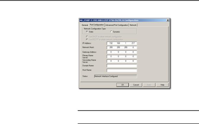
4. Click the Port Configuration tab.
5.For Network Configuration Type, click Static to permanently assign this configuration to the port.
IMPORTANT If you click Dynamic, on a power cycle, the controller clears the current
IP configuration and resumes sending BOOTP requests.
6.Type this information in the appropriate fields:
•In the IP Address field, type the IP address.
•In the Network Mask field, type the network mask address.
•In the Gateway Address field, type the gateway address.
•In the Primary Name Server field, type the name of the primary server.
•In the Secondary Name Server field, type the name of the secondary server.
•In the Domain Name field, type the domain name.
•In the Host Name field, type the host name.
26 |
Rockwell Automation Publication ENET-UM001L-EN-P - March 2014 |

Configure an EtherNet/IP Communication Module to Operate on the Network |
Chapter 3 |
|
|
7. Configure the port settings.
To |
Then |
||
|
|
|
|
Use the default port speed and |
Leave Auto-negotiate port speed and duplex checked. |
||
duplex settings |
This setting determines the actual speed and duplex setting. |
||
|
|
|
|
Manually configure your port’s |
Follow these steps. |
||
speed and duplex settings |
1. |
Clear the Auto-negotiate port speed and duplex checkbox. |
|
|
|||
|
2. |
From the Current Port Speed pull-down menu, choose a port |
|
|
|
speed. |
|
|
3. |
From the Current Duplex pull-down menu, choose the appropriate |
|
|
|
Duplex value, that is, Half Duplex or Full Duplex. |
|
|
|
|
|
|
|
|
|
IMPORTANT Consider the following when you configure the module’s port settings:
•If the module is connected to an unmanaged switch, leave Autonegotiate port speed and duplex checked or the module will fail.
•If you are forcing the port speed and duplex with a managed switch, the corresponding port of the managed switch must be forced to the same settings or the module will fail.
8. Click OK.
Rockwell Automation Publication ENET-UM001L-EN-P - March 2014 |
27 |
Chapter 3 Configure an EtherNet/IP Communication Module to Operate on the Network
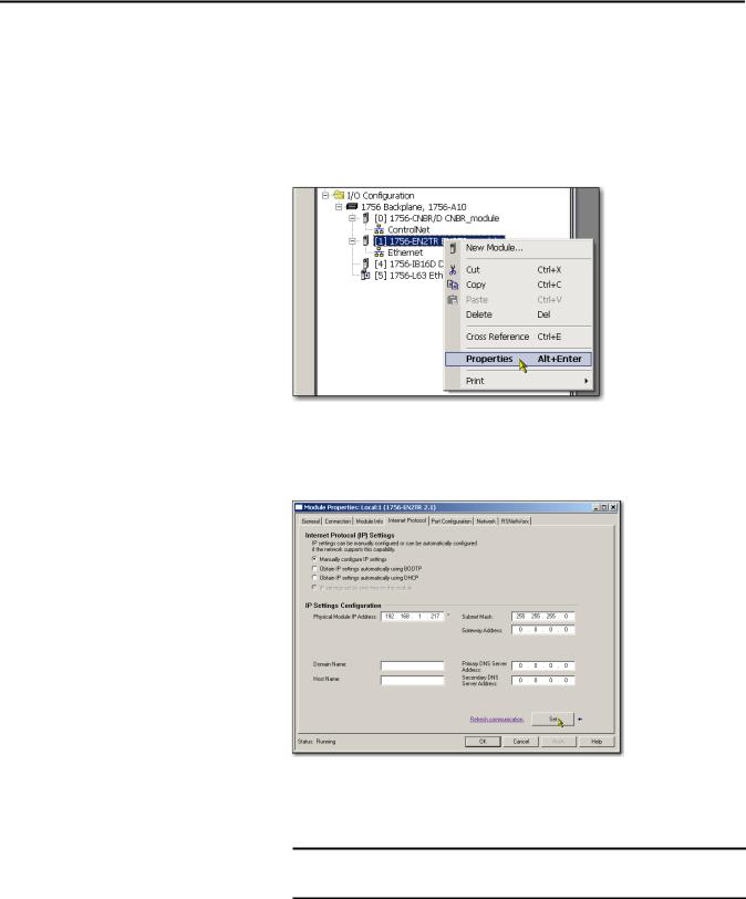
Set the Network IP Address with the Studio 5000 Environment
To use the Studio 5000 environment to set the communication module’s IP address, follow these steps.
1.In the Controller Organizer, right-click the EtherNet/IP module and choose Properties.
The Module Properties dialog box appears.
2. Click the Port Configuration tab.
3.In the IP Address field, type the IP address.
4.In the other fields, type the other network parameters, if needed.
IMPORTANT The fields that appear vary from one EtherNet/IP module to another.
5.Click Set.
6.Click OK.
28 |
Rockwell Automation Publication ENET-UM001L-EN-P - March 2014 |
Configure an EtherNet/IP Communication Module to Operate on the Network |
Chapter 3 |
|
|
Duplicate IP Address
Detection
Reset the Module IP Address to Factory Default Value
You can reset the module’s IP address to its factory default value with the following methods:
•If the module has rotary switches, set the switches to 888 and cycle power.
•If the module does not have rotary switches, use a MSG instruction to the reset the IP address.
Some EtherNet/IP communication modules support duplicate IP
address detection. The module verifies that its IP address does not match any other network device’s IP address when you perform either of these tasks:
•Connect the module to a EtherNet/IP network.
•Change the module’s IP address.
If the module’s IP address matches that of another device on the network, the module’s EtherNet/IP port transitions to Conflict mode. In Conflict mode, these conditions exist:
•OK status indicator is blinking red.
•Network (NET) status indicator is solid red.
•On some EtherNet/IP communication modules, the module status display indicates the conflict.
The display scrolls:OK <IP_address_of_this_module> Duplicate IP
<Mac_address_of_duplicate_node_detected>
For example: OK 10.88.60.196 Duplicate IP - 00:00:BC:02:34:B4
•On some EtherNet/IP communication modules, the module’s diagnostic webpage displays information about duplicate IP address detection.
For more information on which EtherNet/IP communication modules support displaying duplicate IP address on their diagnostic webpage, see the Technical Note titled Logix modules Duplicate IP address detection enhancement, #118216, in the Technical Support Knowledgebase available at http://www.rockwellautomation.com/knowledgebase/.
Rockwell Automation Publication ENET-UM001L-EN-P - March 2014 |
29 |

Chapter 3 Configure an EtherNet/IP Communication Module to Operate on the Network
Duplicate IP Address Resolution
When two EtherNet/IP communication modules on a network have conflicting IP addresses, the resolution depends on the conditions in which the duplication is detected. This table describes how duplicate IP addresses are resolved.
Duplicate IP Address Detection Conditions |
Resolution Process |
|
|
|
|
• Both modules support duplicate IP address detection |
1. |
The module that began operation first uses the IP address and continues to operate without interruption. |
• Second module is added to the network after the first |
2. |
The module that begins operation second detects the duplication and enters Conflict mode. |
|
|
|
module is operating on the network |
|
To assign a new IP address to the module and leave Conflict mode, see Set the Network IP Address on a Module |
|
|
on page 18. |
|
|
|
• Both modules support duplicate IP address detection |
Both EtherNet/IP devices enter Conflict mode. |
|
• Both modules were powered up at approximately the same |
To resolve this conflict, follow these steps: |
|
time |
|
a. Assign a new IP address to one of the modules by using the methods described in Set the Network IP |
|
|
Address on a Module on page 18. |
|
|
b. Cycle power to the other module. |
|
|
|
One module supports duplicate IP address detection and a |
1. |
Regardless of which module obtained the IP address first, the second module, that is, the module that does not |
second module does not |
|
support IP address detection, uses the IP address and continues to operate without interruption. |
|
2. |
The module that supports duplicate IP address detection detects the duplication and enters Conflict mode. |
|
|
To assign a new IP address to the module and leave Conflict mode, see Set the Network IP Address on a Module |
|
|
on page 18. |
|
|
|
IP Address Swapping
Devices experiencing duplicate IP address conditions behave differently depending on whether connections have been established to either of the modules and whether both modules support duplicate IP address detection.
Some EtherNet/IP communication modules support IP address swapping. This functionality is used in ControlLogix enhanced redundancy systems. During a system switchover, partnered EtherNet/IP communication modules swap IP addresses.
For more information about IP address swapping, see the ControlLogix
Enhanced Redundancy System User Manual, publication 1756-UM535.
30 |
Rockwell Automation Publication ENET-UM001L-EN-P - March 2014 |
Loading...